International Research Journal of Engineering and Technology (IRJET)
e-ISSN: 2395-0056
Volume: 05 Issue: 11 | Nov 2018
p-ISSN: 2395-0072
www.irjet.net
Design and Finite Element Analysis of Fabricated Panama chock with 225T capacity Satyanarayana K V V1 1M.Tech
Naval Architect and Marine Engineering, Andhra University college of Engineering, Visakhapatnam
------------------------------------------------------------------***--------------------------------------------------------------------Abstract:- Panama chocks are used specifically for the guidance of rope mooring/towing lines on board a large ship or vessel. Intended for heavy duty use, the chocks are generally manufactured from high quality cast steel in various grades dependent upon the particular application and loadings required. Panama Chocks can be either, or alternatively can come supplied with a base plate to be welded to a plinth.
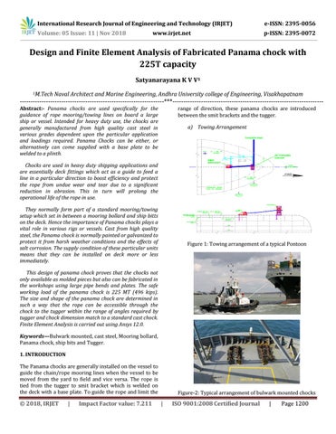
range of direction, these panama chocks are introduced between the smit brackets and the tugger. a) Towing Arrangement TUGGER END
M. H
P - 1 WB TK UNDER
(N) PANAMA CHOCK
1 4 ' - 57 8" 6 81 "
Chocks are used in heavy duty shipping applications and are essentially deck fittings which act as a guide to feed a line in a particular direction to boost efficiency and protect the rope from undue wear and tear due to a significant reduction in abrasion. This in turn will prolong the operational life of the rope in use.
[4417]
[155]
SMIT BRACKET
P ORT P ONTOON
P - 2 WB TK UNDER
74 TH RUSTER ROOM FWD ( P ) UNDER
72
PANAMA CHOCK
They normally form part of a standard mooring/towing setup which set in between a mooring bollard and ship bitts on the deck. Hence the importance of Panama chocks plays a vital role in various rigs or vessels. Cast from high quality steel, the Panama chock is normally painted or galvanized to protect it from harsh weather conditions and the effects of salt corrosion. The supply condition of these particular units means that they can be installed on deck more or less immediately.
( E) B H D 1 4 m m `AH' ( REF.NO.1 )
SMIT BRACKET
( E) PL. 1 2 m m `AH' ( REF.NO.1 )
LOWER H ULL TOP DEC K EL. 3 1 ' - 2 " AB L [9500] ( E) L 1 5 0 x 9 0 x 1 2 m m `AH' ( REF.NO.1 ) ( E) AIR DUC T ( INB D) - DO-
- DO-
Figure 1: Towing arrangement of a typical Pontoon
This design of panama chock proves that the chocks not only available as molded pieces but also can be fabricated in the workshops using large pipe bends and plates. The safe working load of the panama chock is 225 MT (496 kips). The size and shape of the panama chock are determined in such a way that the rope can be accessible through the chock to the tugger within the range of angles required by tugger and chock dimension match to a standard cast chock. Finite Element Analysis is carried out using Ansys 12.0. Keywords—Bulwark mounted, cast steel, Mooring bollard, Panama chock, ship bits and Tugger. 1. INTRODUCTION The Panama chocks are generally installed on the vessel to guide the chain/rope mooring lines when the vessel to be moved from the yard to field and vice versa. The rope is tied from the tugger to smit bracket which is welded on the deck with a base plate. To guide the rope and limit the
Š 2018, IRJET
|
Impact Factor value: 7.211
Figure-2: Typical arrangement of bulwark mounted chocks
|
ISO 9001:2008 Certified Journal
|
Page 1200