International Research Journal of Engineering and Technology (IRJET)
e-ISSN: 2395-0056
Volume: 05 Issue: 11 | Nov 2018
p-ISSN: 2395-0072
www.irjet.net
SPEED LIMIT ALERTING DEVICE Priyanka Pal1, Priyanka Chaurasia2 1,2Dept. of Electronics Engineering, Vidyalankar Institute of Technology, Maharashtra, India -------------------------------------------------------------------------***------------------------------------------------------------------------
Abstract - The project is aimed at improving the safety and flow of traffic utilizing traffic capacity more effectively. There are so many traffic rules for reliable life which we break intentionally or unintentionally. Some of them can result to critical. Our project is mainly based upon the same thing. Our idea is to let it know for bikes about such zones (School/Hospital/Police) to avoid accident in school area, to keep quite in hospital area. The main objective is to design a Smart Display controller meant for bike’s speed control and monitors the zones, which can run on an embedded system. Display & Control can be custom designed to fit onto a bike’s dashboard, and displays information on the bike. The project is composed of two separate units: zone status unit and speed display and control unit. Once the information is received from the zones, the bike’s embedded unit automatically alerts the driver, to reduce the speed according to the zone, it waits for few second, then if the bike is in the speed limit and the bike’s speed is still not reduced below that speed limit, the number of the bike and the owners detailed will be sent to RTO (we have assumed a third party) through SMS.
2. OVERVIEW
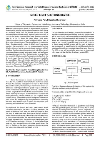
The system will provide a safety measure for bikers which is not effectively implemented before .With this system there will be reduction in traffic rules violation and accident rates done by bikers by huge amount .It will provide a GPS module which will do most of the task getting the location of the area, no entry, no parking will be used to avoid rule violation in those areas. An LCD screen will be used to indicate warning as well as speed limit which will be needed to be maintained or different message depending upon the area. The LCD screen will also display a message if violation of rules occurred that the bike details are sent to RTO. 3. METHODOLOGY
CONVERTER
POWER SUPPLY
Key Words: Raspberry Pi 3 Model B Raspbian Stretch, OS, PL2303HX Converter, Neo 6m v2 GPS Module. 1. INTRODUCTION
RASPBERRY
ANDROID
Pi TFT LCD
Due to the increase in number of automobiles on the road it is not possible to monitor all area and speed zones. Most of the accidents are supposed to occur in these areas. Because the traffic police cannot go everywhere means it is difficult to control people to over speed. They do not bother about human lives so the project provides a technique to control people to follow the traffic rules in certain areas. There are many techniques available to avoid accidents like blink preventing, cruise control (cc) or Adaptive cruise control (ACC). These techniques are being used for vehicles such as cars. We are specifically doing almost the same thing for bikes. Here a GPS is used to detect and control the over speeding and other traffic rules problems.
Display Fig 1.Block diagram To achieve the desired aim and objective of this project, the following methods are to be adopted. To implement the project the following module used are 1) Raspberry Pi 3 Model B 2) GPS Module 3) PL2303HX Converter 4) R-pi TFT Display Firstly, the desired locations such as speed limit areas along with the specified speeds, the silence zones, the no entry areas, etc. according to the location (latitude, longitude) coordinates are already stored in the microcontroller. The Speedometer continuously calculates the speed of the bike. It uses two GPS points (locations), we can calculate the distance covered. We can use the clock inside the GPS receiver (a very accurate clock that synchronizes regularly with the atomic clocks aboard the GPS satellites) to measure how long it took the vehicle to travel between those two points. The speed from the speedometer is than compared to the speed limit of the speed limit area in which the bike is. If the speed exceeds than the speed limit a warning is display. The Microcontroller than waits for 10 seconds for the rider
To implement this system, we have a speedometer which calculates the speed of the bike, a GPS map which gets the speed of the speed limit zone and both are compared with the help of microcontroller. As soon as the bike enters a speed limit zone, a warning to keep the speed below the limit is given. After waiting for few seconds if the speed doesn’t decrease below the limit, the details of the bike’s owner goes to RTO (we have assumed a third party). Similarly for silence zone, we have a sound detection sensor which senses the horn of the bike in the silence zones and after the warning the microcontroller sends the details to RTO.
© 2018, IRJET
GPS
|
Impact Factor value: 7.211
|
ISO 9001:2008 Certified Journal
|
Page 881