International Research Journal of Engineering and Technology (IRJET)
e-ISSN: 2395-0056
Volume: 05 Issue: 10 | Oct 2018
p-ISSN: 2395-0072
www.irjet.net
Intravenous Fluid Level Indicator Arulious Jora A1, Divya Laveena A2, Earlina D3, Nirmala S4 1,2,3,44th Year
Electrical Engineering, Loyola - Icam College of Engineering and Technology, Chennai, Tamil Nadu, India. -------------------------------------------------------------------------***-----------------------------------------------------------------------idea is proposed to develop an effective health monitoring Abstract - With the increased growth of the population,
system which alerts the doctor or nurse when the fluid level of the saline bottle is below the threshold limit.
health care plays a vital role in leading a contented life. In hospitals, ensuring the patients’ safety is the most important thing. Hence automatic health monitoring systems are the most sought after because it gives precise information while reducing the stress of the medical practitioners and the bystanders of the patient about missing certain critical data. Also, indicating when the intravenous fluid administered to the patient falls below a critical level is a tedious process and a tougher job. Monitoring the level of intravenous fluid level manually is a simpler job but if not done with utmost care may affect the health of the patient severely. This may lead to blood loss or backflow of blood to IV tube from their veins. If the bottle gets fully drained, air enters the tube and in turn into the vein, which may prove disastrous to the patient. So automating this system might prove really helpful. A system is designed such that if the Intravenous fluid reaches a critical level, it is sensed by the LED and LDR set up and an alarm is sounded at the nurses’ room indicating the room number. When this is done, the nurse can easily identify the room and go there directly to change the bottle rather than keep checking every room to notice if the fluid has reached the critical level. This requires the use of RF transmitters and receivers to transmit to distances.
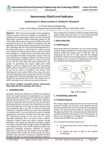
2. NEED ANALYSIS 2.1 Bull Diagram Intravenous fluid level indicators are very much essential to assist medical practitioners to take proper care and the patients’ health. Our project aims to fulfill the same by monitoring the level of IV fluid and alert the medical practitioner whenever the level goes below a critical value thus aiding in the removal of IV medication once it gets over and hence preventing the backflow of blood.
Key Words: Arduino Controller, Buzzer, Intravenous fluid, LDR, LED, RF Transmitter, RF receiver.
1. INTRODUCTION
Fig - 1: Bull Diagram
Generally, intravenous therapy is a medical procedure in which the liquid substances (medications) are directly inserted into the vein through an IV tube and a needle is inserted into the patients’ vein. A sealed device called drip chamber controls the entire process so that the substance slowly pass into the vein, and it also blocks the air to enter into the bloodstream. An IV drip is usually used for longterm treatments. But it can also be used for short-term treatment to rehydrate patients or to give them medicines to revitalize them. It is a very efficient process for quickly supplying the prescribed medicines into the entire body. The intravenous therapy is not only used to correct electrolyte imbalances but it can also be used to deliver medicines. Patients those who cannot consume enough nutrients or who cannot eat at all due to an illness, surgery or accident, can be fed with enough nutrition through their vein using IV therapy. These sterile solutions (sodium and dextrose) containing necessary nutrients to support human life is injected into the patient’s body through a tube attached to the needle. Due to the lack of care, many problems will arise such as blood loss, backflow of blood through an IV tube. To overcome this situation an effective
© 2018, IRJET
|
Impact Factor value: 7.211
3. FUNCTIONAL ANALYSIS 3.1 Octopus Diagram The octopus diagram represents the service functions. The product to design is in the center of the diagram., and the external elements (EE) of the environment are positioned around. The primary function links to external elements through the product. The constraint function links directly an external element to the product. It is a characteristic, an effect or an arrangement of design that is mandatory or that has been forbidden for any reason. For our project the primary functions are
|
●
To measure the level of the IV fluid in the drips bottle.
●
To indicate the level of fluid to the medical practitioners.
ISO 9001:2008 Certified Journal
|
Page 525