INTERNATIONAL RESEARCH JOURNAL OF ENGINEERING AND TECHNOLOGY (IRJET) VOLUME: 05 ISSUE: 10 | OCT 2018 WWW.IRJET.NET
E-ISSN: 2395-0056 P-ISSN: 2395-0072
MITIGATION OF HARMONICS IN ACTIVE NEUTRAL POINT CLAMPED ULTILEVEL INVERTER MR. BISWA BHUSAN
DAS 1, BHENUKA KHARE 2
1,2DEPARTMENT OF ELECTRICAL ENGINEERING, CSVTU UNIVERSITY, BHILAI ---------------------------------------------------------------------***----------------------------------------------------------------------------
Abstract:- Multilevel inverter is one of the most recent and popular type of advances in power electronics. It synthesizes desired output voltage waveform from several dc sources used as input for the multilevel inverter.
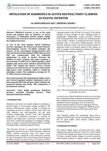
clamping points in the DC-link (P, O and Q). The control strategy to keep voltages of each clamping points is complicated. Additionally, reverse recovery currents from clamping diodes will increase the switching losses of the system. Another conventional five-level inverter topology type is Five-Level Flying-Capacitor (5L-FC) inverter. As shown in Fig. 1 (b), the increased number of capacitors leads to increased volume of the system as well as complex control method to balance the voltages of both DC-link capacitors and FCs.
As one of the most popular hybrid multilevel inverter topologies, the Seven-Level Active-NeutralPoint-Clamped inverter (7L-ANPC) combines the features of the conventional Flying-Capacitor (FC) type and Neutral-Point-Clamped (NPC) type inverter and was commercially used for industrial applications. In order to further decrease the number of active switches, this paper proposes a Seven-Switch 7L-ANPC (7S-7L-ANPC) topology, which employs only seven active switches and two discrete diodes. The analysis has shown a lower current rating can be selected for the seventh switch under high power factor condition, which is verified by simulation results. The modulation strategy for 7S7L-ANPC inverter is discussed. Our project presents the fundamental voltage source and current-regulated method. Simulation work is done using the MATLAB software which validates the proposed method and finally THD comparison is presented for analysis.
Fig. 1. The conventional five level inverter topologies. (a) 5L-NPC. (b) 5L-FC.
KEYWORDS: Pulse Width modulation, Multilevel Inverter, Cascaded H-Bridge Inverter, Total Harmonic Distortion, Matlab
In recent years, hybrid multilevel inverters are receiving more attentions in both academia and industry because they combine the features of many conventional multilevel inverter topologies. As one of the most popular hybrid multilevel inverter topologies, the FiveLevel Active-Neutral-Point-Clamped (5L-ANPC) inverter combines the characteristics of NPC type and FC type inverters.
1 INTRODUCTION Multilevel converters are mainly utilized to synthesis a desired single- or three-phase voltage waveform. The desired multi-staircase output voltage is obtained by combining several dc voltage sources. Solar cells, fuel cells, batteries and ultra-capacitors are the most common independent sources used. One important application of multilevel converters is focused on medium and high-power conversion. Nowadays, there exist three commercial topologies of multilevel voltagesource inverters: neutral point clamped (NPC), cascaded H-bridge (CHB), and flying capacitors (FCs).
This topology enables the modularity factor that is lacking in the NPC type inverter by adding the FC power cell to reach higher level without adding seriesconnected diodes. 2 PROBLEM STATEMENT
The five-level inverter is a good choice for industrial application because of lower Total Harmonic Distortion (THD), reduced switching stress and hence lower switching losses compared to the three-level inverter. For the conventional Five-Level Neutral-Point-Clamped (5L-NPC) inverter, as shown in Fig. 1 (a), there are three
Š 2018, IRJET
|
Impact Factor value: 7.211
The typical voltage source inverters gives the output voltage at the poles with levels +Vdc/2 or –Vdc/2 which is the DC link voltage also known as two level inverter. To attain a quality output voltage or current waveform with minimal number of ripple content, it needs high
|
ISO 9001:2008 Certified Journal
|
Page 326