International Research Journal of Engineering and Technology (IRJET)
e-ISSN: 2395-0056
Volume: 05 Issue: 10 | Oct 2018
p-ISSN: 2395-0072
www.irjet.net
STRUCTURAL AND MODAL ANALYSIS OF SUBSONIC AIRCRAFT WING USING ANSYS WORKBENCH Kathiravan.T1, Mohammed Huda.A2, Parthiban.K3 Student, Sapienza University of Rome Anna University-Chennai ---------------------------------------------------------------------***--------------------------------------------------------------------1, 2
3Student,
Abstract:- Structural analysis is an important part of the design and development of the aircraft structure. Design of airplanes depends on their wings for flight. The wing of an airplane is one of the most important and complicated element. The wings are the most important lift-producing part of the aircraft. Wings vary in design depending upon the aircraft type and its purpose. A wing is a type of fin with a surface that produces aerodynamic force for flight through the atmosphere. The lift force is directed upwards and is acting perpendicular to the displacement of the wing and the drag force is exerted in the direction opposed to the displacement of the plane. Hence, this presentation includes the detailed analysis of the structural analysis of wing. The main purpose of this project is to find out which material (Al alloy and Ti alloy) is best suited for making of wing for subsonic flight. In this the NACA-4 digit series is used for making wing skeleton structure and later we made modelling and structural analysis on wing Skelton structure by using ANSYS WORKBENCH. Structural analysis of the wing is carried out to compute the stresses due to pressure and various loads. The modelling, analysis and stresses are estimated using the Ansys software.
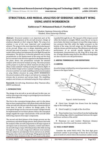
is pushed through the air. The top part of the wing is curved while the bottom is straight. Which cause the air on top to move faster, the faster moving air on top of the wing creates a low pressure that lifts while the higher pressure on the bottom of the wing. Aircraft wings are the lifting surfaces with the chosen aerofoil sections. The efficiency as well as the performance of an aircraft mostly depends on the aerodynamic characteristics e.g. lift, drag, lift to drag ratio, etc. of wings. Besides many factors, the effects of wing shape are also crucial to aircraft performance. 2. AIRFOIL TERMINOLOGY AND DEFINITIONS 2.1AIRFOIL An airfoil shape is defined by several parameters, which are shown in the figure below.
Keywords: Aircraft wing, Aluminium alloy, Titanium alloy, ANSYS workbench. 1. INTRODUCTION The design of an aircraft or an aircraft part (in this case, we will be referring to the wing) is a prolonged process that has mainly three phases; Figure1: Airfoil Geometry
The first is the conceptual design phase, and it is the phase that we have employed here, this phase deals with the layout of the aircraft/aircraft part and what major characteristics it must have in order to achieve its design goals, if the conceptual design is to be a success no major changes should be implemented on it in future phases. Hence, the conceptual design engulfs the major characteristic of the aircraft while delivering a layout of its major components.
Chord Line: Straight line drawn from the leading edge to the trailing edge Chord Length (c): Length of the chord line Mean Camber Line: Curved line from the leading edge to the trailing edge, which is equidistant between the upper and lower surfaces of the airfoil
The second and third phases of the design process are the preliminary and detail design phases; these phases deal with the analysis of the aircraft components in all major aspects of aerospace such as structures, dynamics, control and others. An aircraft wing is a type of fin that produce lift, while moving through air or. As such, wings have efficient cross-sections that are subject to aerodynamic forces and act as an airfoils. Wing play a key role in aircraft design. Wings generate the lift required to keep airplanes in the air. Lift occurs as the plane
© 2018, IRJET
|
Impact Factor value: 7.211
Maximum (or just) Camber: Maximum distance between the chord line and the mean camber line. 2.2 NACA 4-DIGIT SERIES Consider the airfoil NACA 4412. The first digit gives maximum camber in percentage of chord, the second digit gives in tenth of a chord where the maximum camber occurs,
|
ISO 9001:2008 Certified Journal
|
Page 823