International Research Journal of Engineering and Technology (IRJET)
e-ISSN: 2395 -0056
Volume: 04 Issue: 06 | June -2017
p-ISSN: 2395-0072
www.irjet.net
Study of Three State Switching Cell Based DC-To-DC Converter P.ManojBharath1 ,Dr.K.Subramanian2 1Assistant
Professor, Shri Sitheswarar Engineering College, Arcot – 632 503, Vellore District, Tamil Nadu. India 2Associate Professor, Dept. of Energy And Power Electronics, School of Electrical Engineering VIT University, Vellore, Tamil Nadu, India, 632014 ---------------------------------------------------------------------***---------------------------------------------------------------------
In the last few years, the converter based on three state switching cells (3SSC) has been proposed, development of this converters reported by different authors [11]-[14].
Abstract— Needs of variable dc power supply increased due to industrial growth. Variable speed induction motor drives are widely used in most of the industries by using V/F control technique. In order to meet the high energy level of d.c supply for those drives three-phase diode rectifier followed by the dcto-dc converters employed for that with high energy level. Buck-boost operation of dc-to-dc converter employed in emerging application such as photovoltaic cell or fuel cell as a dc source for a vehicle drives with high gain dc voltage. This paper investigate the performance of a dc-dc converter consists of high gain voltage multiplier. It is three state switching cells of capacitors. A 1kW prototype model of dc-todc converter is fabricated and tested. Computer simulation of this scheme completed using the power system toolbox built-in libraries of MATLAB / SIMULINK software. The results are presented.
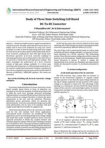
The aim of this work is experimental study on a three-state switching cell based voltage multiplier, incorporate in buckboost operation of a DC-DC converter. The forthcoming section-2 describes the system configuration of three-state cell based dc-to-dc development. Matlab based simulation of the circuit discussed in section 3, section 4 explain the experimental work carried out. Simulated and experimental results are discussed in section -5, conclusion presented in section 6. II. System Configuration A.Cuk mode operation of dc-dc converter The CUK converter, Fig.1, named after its inventor, is similar to the buck-boost regulator, to regulate output voltage is greater or less than the input voltage depends on the input voltage magnitude but the polarity of the output voltage is in opposite to input [15]. The advantage of the topology is a continuous current at both the input and the output of the converter and needs high number of reactive components and high current stresses on the switch, diode, and the capacitor C1.
Key words:switching cell, dc-to-dc converter, voltage multiplier
I. Introduction At present, implementations of power electronics circuit based variable speed drives in most of industries are essential, to increase the quantity of industrial products and to fulfill the work force shortage advanced technology implementation is essential. Modern power electronic device and its controls are compact therefore; it reduces the space requirement of the new and old industries. Moreover distributed power generators, which are generate the electrical power from non-conventional energy sources like wind, photovoltaic cell etc, have to be interface with grid supply needs high level variable dc supply[1]-[5]. Buck-boost operations of dc-to-dc converters are widely used for low and medium level drives applications. Conventional boost converters are insufficient for high applications, due to its switching at high-level voltage ratings and small duty cycles. Coupled inductors boost converter approach presented in details [6], coupled inductor and switched capacitor scheme without extra windings presented by Yi-Pin Hsieh et al [7]. The same technique implemented in sustainable energy system [8].The design, analyses and losses calculation of those converters are describing analytically and verified experimentally presented in detail [9] - [10].
© 2017, IRJET
|
Impact Factor value: 5.181
Fig. 1 CUK dc –to-dc converter Dc to dc regulator operation of CUK converter, Fig.1, consist of DC input voltage source , energy transfer capacitor , controlled switch , inductor capacitor ‘C’, and load resistance ‘R’.
, filter
Figure 2 illustrates the voltage and current waveforms. Let the switch ‘S’ is on, the diode is off and the capacitor C 1 is
|
ISO 9001:2008 Certified Journal
| Page 3235