International Research Journal of Engineering and Technology (IRJET)
e-ISSN: 2395 -0056
Volume: 04 Issue: 06 | June -2017
p-ISSN: 2395-0072
www.irjet.net
Design and Development of Hydraulic Solar Tracking System Akshay Kandave1, Shubham Kadam2, Amol Shinde3 SaurabhSagalgile4 1,2,3,4Students,
Alard College of Engineering, Pune ------------------------------------------------------------------------------***-------------------------------------------------------------------
Abstract: Nowadays solar power considered as reliable energy source for power generation and for many other applications. The challenge is to fetch maximum amount of energy from solar radiations in which sun is continuously changing its position in sky. There are many problems associated with conventional solar panel because they are fixed in one direction.The positions of the sun keeps on changing every day, along with the sun, solar panel have to move in same direction.The other system also used for solar tracking but they consumes most of the energy produced by solar panels for tracking, which effects the efficiency of solar panel.
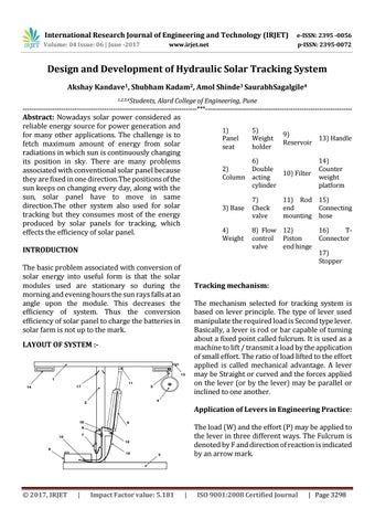
1) Panel seat
5) Weight holder
9) 13) Handle Reservoir
6) 2) Double 10) Filter Column acting cylinder 3) Base 4) Weight
INTRODUCTION The basic problem associated with conversion of solar energy into useful form is that the solar modules used are stationary so during the morning and evening hours the sun rays falls at an angle upon the module. This decreases the efficiency of system. Thus the conversion efficiency of solar panel to charge the batteries in solar farm is not up to the mark.
7) Check valve
14) Counter weight platform
11) Rod 15) end Connecting mounting hose
8) Flow 12) 16) Tcontrol Piston Connector valve end hinge 17) Stopper
Tracking mechanism: The mechanism selected for tracking system is based on lever principle. The type of lever used manipulate the required load is Second type lever. Basically, a lever is rod or bar capable of turning about a fixed point called fulcrum. It is used as a machine to lift / transmit a load by the application of small effort. The ratio of load lifted to the effort applied is called mechanical advantage. A lever may be Straight or curved and the forces applied on the lever (or by the lever) may be parallel or inclined to one another.
LAYOUT OF SYSTEM :-
Application of Levers in Engineering Practice: The load (W) and the effort (P) may be applied to the lever in three different ways. The Fulcrum is denoted by F and direction of reaction is indicated by an arrow mark.
Š 2017, IRJET
|
Impact Factor value: 5.181
|
ISO 9001:2008 Certified Journal
| Page 3298