International Research Journal of Engineering and Technology (IRJET) Volume: 04 Issue: 03 | Mar -2017
e-ISSN: 2395 -0056
www.irjet.net
p-ISSN: 2395-0072
“Minimizing Penalty in Industrial Power Consumption By Engaging APFC Unit”: A Review Nidhi A. Ganatra1 1.2B.E 3.
Swati C. Chotaliya2
Prof Vishal N. Jogidas3
in Electrical Engineering, DSTC, Junagadh, Gujarat, India
Assistant Professor in Electrical Engineering Department, DSTC, Junagadh, Gujarat, India
---------------------------------------------------------------------***--------------------------------------------------------------------1.2 POWER FACTOR Abstract-In the industrial sector the various motoring loads are continuously running and increasing the inductive load. So the power factor in this system get reduces due to the inductive reactive power. But the electricity board has a standard limit regarding the power factor values and if the power factor goes below the specified limit the electricity company charges the penalty to the industrial consumers. APFC device reads power factor from line voltage and line current by determining the delay in the arrival of the current signal with respect to voltage signal from the function generator with high accuracy by using an internal timer. This time values are the calibrated as phase angle and corresponding power factor. Then the values are displayed in Liquid crystal display modules. Then the motherboard calculates the compensation requirement and accordingly switches on different capacitor banks. This is developed by using AVR microcontroller.
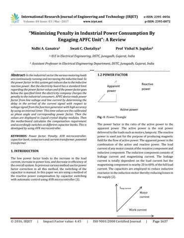
Reactive power
Apparent power
Active power Fig -1: Power Triangle The power factor is the ratio of the active power to the apparent power .The active power is the real power delivered to the loads such as motors, lamps etc. The reactive power is used just for the purpose of producing magnetic field for the flow of active power. The apparent power is the combination of the active and reactive power. The load current of any motor consist of the resistive component and inductive component. The inductive component consists of leakage current and magnetizing current. The leakage current is totally dependent on the load current but the magnetizing component is nearby 20 to 60% of the full load current. The capacitors are employed to reduce inductive reactance in the induction motor thereby reducing losses in the supply [2].
KEYWORDS: Power factor, Penalty, AVR microcontroller, capacitor bank, contactors and current transformer, potential transformer
1. INTRODUCTION The low power factor leads to the increase in the load current, increase in power loss, and decrease in efficiency of the overall system. In previous various method use for power factor correction in all this method, the switching of the capacitor is manual. In this paper we are using a method of the reactive power compensation by capacitor switching with automatic control using AVR microcontroller [1].
Imag current Motor current
Work current
© 2016, IRJET
|
Impact Factor value: 4.45
|
ISO 9001:2008 Certified Journal
|
Page 1637