International Research Journal of Engineering and Technology (IRJET) Volume: 03 Issue: 09 | Sep-2016
www.irjet.net
e-ISSN: 2395 -0056 p-ISSN: 2395-0072
Power quality improvement and ripple cancellation in zeta converters Mariamma John1, Jois.K.George2 1 Student, 2Assistant
Kottayam Institute of Technology and Science, Chengalam, Kottayam, India Professor, Kottayam Institute of Technology and Science, Chengalam, Kottayam, India
---------------------------------------------------------------------***---------------------------------------------------------------------
Abstract - This paper presents a power factor corrected
The operation of an isolated zeta converter is classified into three different modes corresponding to switch turn-ON, switch turn-OFF, and DCM. Three modes are shown in Figure below and their associated waveforms are shown in Fig. 3. These modes are described as follows.
(PFC) zeta converters a cost effective solution for low power applications. In this work by adjusting the dc link capacitor voltage, we can use this converter for various low power applications. This paper deals with the implementation of pulse width modulated Zeta converter. A MATLAB/Simulink environment is used to simulate the model. Key Words: Zeta converter, Power factor correction (PFC) 1.INTRODUCTION Zeta converter topology provides a positive output voltage from an input voltage that varies above and below the output voltage. The zeta converter also needs two inductors and a series capacitor sometimes called flying capacitor. Unlike the SEPIC converter, which is configured with a standard boost converter, the zeta converter is configured from buck controller that drives a high-side P-MOSFET. The zeta converter is another option for regulating an unregulated input-power supply, like a low cost wall wart.
Fig -1: Equivalent circuit of zeta converter
2. PFC BASED ZETA CONVERTER
Are equal to
2.1 Operation of Zeta converter
voltage equal to . Inductor get energy from voltage source and there respective currents increased
This converter is the latest type of single-stage input current shapers. It also uses single switching device and inherently provides an overload, short circuit, and inrush current protections. Since zeta converters behave as a resistive load to input AC mains, these converters are also called resistance emulators. Zeta converter is fourth order converters that can step down or step up the input voltage. The Zeta converter has many advantages, such as buck-boost capability, and continuous output current, input to output DC insulation, so it can be used in high reliability system. This topology offer high efficiency, especially by using the synchronous rectification. The synchronous rectification can be easily implemented in this converter, because this topology, unlike the SEPIC converter, uses a low-side rectifier. The equivalent circuit of the Zeta converter is in figure
linearly by
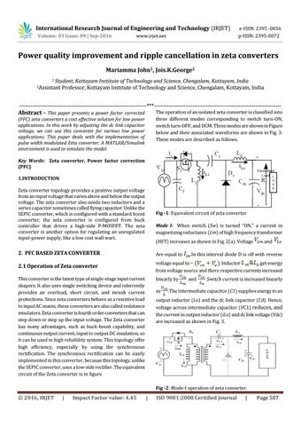
Mode I: When switch (Sw) is turned “ON,” a current in magnetizing inductance (Lm) of high frequency transformer (HFT) increases as shown in Fig. 2(a). Voltage
as
and
.In this interval diode D is off with reverse
and
.Switch current is increased linearly
.The intermediate capacitor (C1) supplies energy to an
output inductor (Lo) and the dc link capacitor (Cd). Hence, voltage across intermediate capacitor (VC1) reduces, and the current in output inductor (iLo) and dc link voltage (Vdc) are increased as shown in Fig. 3.
Fig -2: Mode-I operation of zeta converter.
© 2016, IRJET
|
Impact Factor value: 4.45
|
ISO 9001:2008 Certified Journal
|
Page 507