International Research Journal of Engineering and Technology (IRJET) e-ISSN: 2395-0056
Volume: 12 Issue: 04 | Apr 2025 www.irjet.net p-ISSN: 2395-0072


International Research Journal of Engineering and Technology (IRJET) e-ISSN: 2395-0056
Volume: 12 Issue: 04 | Apr 2025 www.irjet.net p-ISSN: 2395-0072
P V Mallari1 , Sai Rohith G2
1-2 UG Students, Department of Mechanical Engineering, RYM Engineering College, Ballari, Karnataka, India
Abstract - This research is to analyze the performance of the slider-crank mechanism by using MSC Adams/View software. Using the Lagrangian approach, a dynamic model was established by considering the effect of faults induced by heavy clearance. Furthermore, three-dimensional simulation of the model was verified. The study reveals that the gaps existing between the joints of the mechanism have a considerable impact on the response of mechanisms, hence increasing vibration, shock, and shifts in critical system parameters including but not limited to displacement, speed, and acceleration. The impacts are magnified with higher levels of clearance.
Key Words: Slider-crank mechanism MSC Adams/View, Dynamic simulation, Kinematic analysis, Multibody dynamics
MSC Software is recognized as one of the pioneering companiesinthesoftwareindustry,standingoutasaglobal leader in enabling manufacturers to enhance their engineering processes through simulation software and services. As a trusted collaborator, MSC Software assists organizationsinimprovingproductquality,reducingdesign andtestingtime,andcuttingcostsassociatedwithproduct development.Thecompany'stechnologyiswidelyusedby academicinstitutions,researchers,andstudentstobroaden their understanding and further the capabilities of simulation.
MSC Software's simulation tools are utilized by top manufacturers for a wide range of applications, including linearandnonlinearfiniteelementanalysis(FEA),advanced material modeling, acoustics, fluid-structure interaction (FSI), multi-physics, optimization, fatigue and durability analysis,multi-bodydynamics,controls,andmanufacturing process simulations. The company's products provide accurateanddependablepredictionsofreal-worldproduct behavior,empoweringengineerstodesignmoreinnovative solutions.
MSCAdams(AutomatedDynamicAnalysisofMechanical Systems)Adamsistheworld’smostwidelyusedmultibody dynamics simulation software. It lets you build and test functionalvirtualprototypes,realisticallysimulatingonyour
omputer,bothvisuallyandmathematically,thefull–motion behaviorofyourcomplexmechanicalsystemdesigns.
Adamsprovidesa robustsolutionenginetosolveyour mechanicalsystemmodel.Thesoftwarechecksyourmodel and automatically formulates and solves the equations of motion for kinematic, static, quasi-static, or dynamic simulations. With Adams, you don’t have to wait until the computations are complete to begin seeing the results of yoursimulation.Youcanviewanimationsandplots –and continuetorefineyourdesign–evenasyoursimulationis running,savingvaluabletime.Fordesignoptimization,you candefineyourvariables,constraints,anddesignobjectives, then have Adams iterate automatically to the design, providingoptimalsystemperformance.
The slider-crank mechanism is a typical reciprocating mechanical system which consists of revolute and translational joints. In practice, motion clearance is inevitable mainly for three reasons: 1 First of all, the assembly clearance (normal clearance) is designed for rotationandslidinghingemovement.Second,fitandfinish errorsaredesignedintothejointcomponentswhentheyare manufactured.Thethirdsource ofirregularclearanceisdue to wear and tear of the motion pair itself. Whether it is, a naturalphenomenon,adesignflaworanassemblydefect, the existence of clearance adversely affects dynamic behavior, especially rub-impact for the slider-crank mechanism.Inrecentyears,alimited
Flores et al. [2] introduced a general approach for modeling and analyzing multi-body dynamics in revolute joints with multiple clearances. In their study, they developedacontinuouscontactforcemodel,basedonelastic Hertztheoryanddissipativeterms,consideringtheactual jointsascollisionbodiesaffectedbygeometricandphysical properties. Their findings emphasized that both the
clearance size and operating conditions are critical for accuratelypredictingthesystem'sdynamicresponse.
Zheng etal.[3, 4] examined thedynamic behaviorofa rigid-flexiblecouplingslider-crankmechanismundernonlubricatedrevolutejointswithclearance.Theyanalyzedthe

International Research Journal of Engineering and Technology (IRJET) e-ISSN: 2395-0056
Volume: 12 Issue: 04 | Apr 2025 www.irjet.net p-ISSN: 2395-0072
impactoffactorssuchasclearancesize,crankshaftspeed, and the number of clearances on the system’s dynamic response,factoringintheelasticdeformationoftherod.
Bauchau et al. [5] developed nonlinear dynamic equationsforflexiblemulti-bodysystemswithclearances, studying the effect of clearance and flexibility on the dynamicresponseofthemechanism.
For cases involving lubrication in frictional conditions, Alshaeretal.[6],Floresetal.[7-9],Tianetal.[10-12],and Zhengetal.[13]investigateddynamicanalysismethodsfor lubricated revolute and ball joints with clearances. They used fluid dynamics theory to calculate the rub-impact contactforceunderlubrication.Theirresultsshowedthat comparedto the dynamiccharacteristicsof thelubricated clearancemodel,thefrictionalcontactforceintheabsenceof lubricationleadstostrongerfluctuationsinthesystem.
To mitigate the negative effects of revolute joints with clearance, Varedi [14] proposed a method using particle swarmoptimizationtooptimizethemassdistributionofthe mechanism,aimingtoreduceoreliminatetheimpactforce at the joint with clearance. The effectiveness of this algorithmwasverifiedthroughapracticalexample.
3. PROCEDURE AND RESULTS FOR SLIDER CRANK MECHANISM
ProblemDescription
Intheslidercrankmechanismlinkageshowninbelow.

Step1.CreateanewAdamsDatabase
a ClickonCreateanewmodel.
b IntheWorkingDirectorysection,navigatetothefolder whereyouwishtosaveyourmodel.
c Enter"slidercrankmechanism"asthenameforthenew model and click OK. Ensure that the gravity setting is configuredtoEarthNormal(GlobalY)andtheunitsare settoMMKS(mm,kg,N,s,deg).

Step2.CreateLinksandJoints
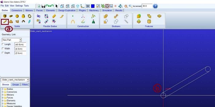
a FromBodiesribbon,doubleclickRigidBody:Link
b Create the link using the specified length, with the markersservingastheendpoints
C FromConnectorsribbon,doubleclickCreateaRevolute joint
d Establish revolute joints between the two links at the designatedpoints
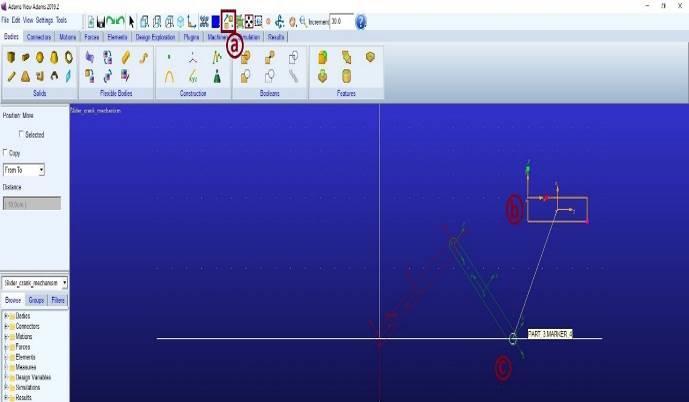
e FromBodiesribbon,doubleclickRigidBody:box
f Create the box using the specified length, with the markers as the endpoints.


International Research Journal of Engineering and Technology (IRJET) e-ISSN: 2395-0056
Volume: 12 Issue: 04 | Apr 2025 www.irjet.net p-ISSN: 2395-0072

Step4.MovetheBox
a frommoverribbon,RightclickRigidMover
b SelecttheBoxandchoosetheCenterPoints
c ClicklinkEndPoint
d Solidifythepartbycreatingthefinalform

Step6.CreateaRevoluteJoints
a FromConnectorsribbon,doubleclickCreateaRevolute joint
b Establish revolute joints between the two links at the specified points

6:AssigningaRevolutejoint.
Step7.CreateTranslationalJoints
a From Connectors ribbon, double click Create a Translationaljoint
b SelectRigidBody:Boxwhenthepromptatthebottomof thescreensays"Selectthefirstbody."
C Select Ground when the prompt at the bottom of the screenasksfor"Selectthesecondbody."
d ChoosePART_2.cmwhenthepromptatthebottomofthe screensays"Selectthelocation."
e Selectcm.Xwhenthepromptatthebottomofthescreen asksfor"Selectthedirectionvector."

7:AssigningaTranslationaljoint.
Step8.AddMotion
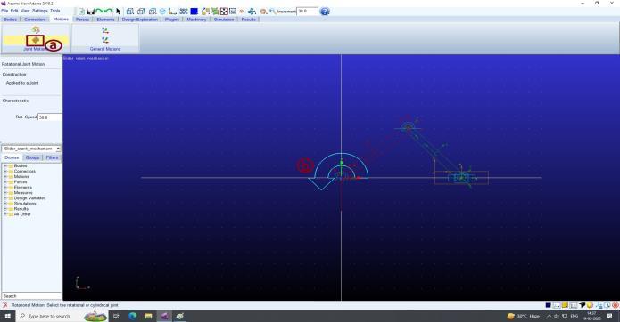
a FromMotionsribbon,selectRotationalJointMotion
b Enter(30rad)inRot.Speedtextfield
c SelectjointatpointO

Step9.TestingtheModel
a From Simulation ribbon, Select Run an Interactive Simulation
b SettheDurationto10andtheStepSizeto500.
C ClickStart.
d ClickonPlotting.
e GenerateaCMPositionPlotforlinkOAintheX component.

International Research Journal of Engineering and Technology (IRJET) e-ISSN: 2395-0056
Volume: 12 Issue: 04 | Apr 2025 www.irjet.net p-ISSN: 2395-0072
f CreateaCMAngularVelocityPlotforLinkABandLink BCinthemagnitudecomponent.
g Followtheplotcurvetodeterminetheangularvelocity

9:SimulatingtheSliderCrankMechanism.

Slider-Crank Mechanism with Clearance Fault SliderCrankMechanismwithClearanceFaultUsingtheLagrange approach, a dynamic model accounting for clearance tolerancesincontinuouscontactconditionswasdeveloped andsimulatedinMSCAdamsakintotheView.Calculating the clearance, or the gap, in the border’s framework will definitelyalterdynamicdisplacement,speed,acceleration, andothervibration.Simulationshowsmaximumclearance resultsdecreaseinterralperformanceandlocusmeasurable changesusingAdams.WiththeaidofAdams/View,amore precisenumericalsimulationsoughttoclarify,andpossibly lessen, the impediments and breakdowns stemmed clearancedefectapology.
[1] FloresP.,AmbrósioJ.,ClaroJ.,LankaraniH.Kinematics and Dynamics of Multibody Systems with Imperfect Joints:ModelsandCaseStudies.Berlin,2007.
[2] FloresP.Aparametricstudyonthedynamicresponseof planarmultibodysystemswithmultipleclearancejoints. NonlinearDynamics,Vol.61,Issue4,2010,p.633-653.
[3] ZhengE.,WangT.,GuoJ.,etal.Dynamicmodellingand error analysis of planar flexible multilink mechanism with clearance and spindle-bearing structure. MechanismandMachineTheory,Vol.131,2019,p.234260.
[4] Zheng E., Zhou X. Modellingand simulation of flexible slider-crankmechanismwithclearanceforaclosedhigh speed press system. Mechanism and Machine Theory, Vol.74,2014,p.10-30.
[5] Bauchau O. A., Rodriguez J. Modelling of joints with clearance in flexible multibody systems.International JournalofSolidsandStructures,Vol.39,Issue1,2002,p. 41-63.
[6] AlshaerB.J.,NagarajanH.,BeheshtiH.K.,LankaraniH. M. Dynamics of a multibody mechanical system with lubricatedlongjournalbearings.JournalofMechanical Design,Vol.127,Issue127,2005,p.493-498.
[7] Flores P., Ambrósio J., Claro J. C. P., Lankarani H. M., KoshyC.S.Astudyondynamicsofmechanicalsystems including joints with clearance and lubrication. MechanismandMachineTheory,Vol.41,Issue3,2006, p.247-261.
[8] Flores P., Ambrosio J., Claro J. C. P., Lankarani H. M., KoshyC.S.Lubricatedrevolutejointsinrigidmultibody systems.NonlinearDynamics,Vol.56,Issue3,2009,p. 277-295.
[9] Flores P., Lankarani H. M. Spatial rigid-multibody systems with lubricated spherical clearance joints: modellingandsimulation.NonlinearDynamics,Vol.60, Issues1-2,2010,p.99-114.
[10]TianQ.,ZhangY.,ChenL.,FloresP.Dynamicsofspatial flexible multibody systems with clearance and lubricatedspherical joints. ComputersandStructures, Vol.87,Issues13-14,2009,p.913-929.
[11]TianQ.,LiuC.,MachadoM.,FloresP.Anewmodelfor dry and lubricated cylindrical joints with clearance in spatialflexiblemultibodysystems.NonlinearDynamics, Vol.64,Issues1-2,2011,p.25-47.
[12]Tian Q., Sun Y., Liu C., Hu H., Flores P. Electrohydrodynamic lubricated cylindrical joints for rigid-flexible multibody dynamics. Computers and Structures,Vol.114,2013,p.106-120.
[13]Zheng E., Zhu R., Zhu S., Lu X. A study on dynamics of flexible multi-link mechanism including joints with clearance and lubrication for ultra-precision presses.

International Research Journal of Engineering and Technology (IRJET) e-ISSN: 2395-0056
Nonlinear Dynamics, Vol. 83,Issues 1-2, 2016, p. 137159.
[14]
VarediS.M.,DanialiH.M.,DardelM.Dynamicsynthesis of a planar slider-crank mechanism with clearances. Nonlinear Dynamics, Vol. 79, Issue 2, 2015, p. 15871600.
BIOGRAPHIES


Volume: 12 Issue: 04 | Apr 2025 www.irjet.net p-ISSN: 2395-0072 © 2025, IRJET | Impact Factor value: 8.315 | ISO 9001:2008
P V Mallari
UGStudentMechanical Engineering,RYMEngineering College,Ballari
Sai Rohith G
UGStudentMechanical Engineering,RYMEngineering College,Ballari