International Research Journal of Engineering and Technology (IRJET)
e-ISSN: 2395 -0056
Volume: 03 Issue: 11 | Nov -2016
p-ISSN: 2395-0072
www.irjet.net
A NOVEL DESIGN AND ANALYSIS OF CIRCULARLY ETCHED UWB ANTENNA FOR L, C AND X-BAND APPLICATIONS Mukesh Kumar1, Ritu Sharma2, Dharti Raj Shah3 1M.Tech
2Asst.
Student, Dept. of ECE, Subharti Institute of Technology & Engineering, Meerut, India Prof., Dept. of ECE, Subharti Institute of Technology & Engineering, Meerut, India 3Asst. Prof., Dept. of ECE, KNGD Modi Engineering College, Modinagar, India
---------------------------------------------------------------------***----------------------------------------------------------
Abstract - In this paper, a circularly etched patch scheme is described to increase the operation bandwidth of antenna for wideband applications. The proposed antenna has compact dimension of 29 mm Ă&#x2014;26 mm with a height of 1 mm and implemented on F4 Epoxy substrate with dielectric permittivity of 4.4. The proposed antenna was simulated using Ansoft High frequency structure simulator (HFSS) electromagnetic simulator. The return losses of designed UWB antenna are good at 1.6 GHz, 4.1 GHz and 8.4 GHz which are < -10 dB and the antenna is useful for L, C and X bands applications respectively. Keywords- Circularly etched, Substrate, bandwidth, HFSS, Return loss, UWB
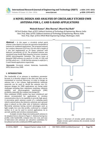
I. INTRODUCTION The bandwidth of an antenna is mandatory parameter because it is directly related to the data rate that can be transmitted or received. Moreover, in order to design an antenna into a low volume, high-permittivity substrate materials can be used to shrink the antenna size [1]. Antenna designs for UWB applications are facing many challenges including their impedance matching, radiation stability, and electromagnetic interference (EMI) problems, especially the compact size design [2]. Ultra wideband (UWB) system has been considered and almost recommended for applications in wireless communication due to its capability to provide high speed. A microstrip patch antenna consist of a radiating patch which is placed above the dielectric substrate and a ground plane is placed on the other side of dielectric substrate Microstrip antennas having several advantages such as light weight, low cost, thin profile, conformal to a shaped surface so it can be used in several applications As in aircraft, satellite and wireless communication. A simple circular shape microstrip patch antenna in its simplest form is shown in Figure 1. Antenna having low profile, wide bandwidth, compact size, low cost, and ease of fabrication slot antennas are attractive candidates for broadband and ultra wideband (UWB) applications.
Š 2016, IRJET
|
Impact Factor value: 4.45
(a)
(b) Figure 1: Structure of circular patch antenna (a) Simple circular patch antenna (b) circularly etched patch antenna
|
ISO 9001:2008 Certified Journal
|
Page 96