International Research Journal of Engineering and Technology (IRJET)
e-ISSN: 2395 -0056
Volume: 03 Issue: 10 | Oct -2016
p-ISSN: 2395-0072
www.irjet.net
FAILURE ANALYSIS OF YOKE JOINT ASSEMBLY Mr. Anuj A. Muley1, Dr. M. J. Sheikh2, Dr. G. V. Thakre3 1
PG Scholar, Mechanical Engineering, Bapurao Deshmukh College of Engineering, Sevagram, Wardha , Maharashtra , India. 2 Professor, Mechanical Engineering, Bapurao Deshmukh College of Engineering, Sevagram, Wardha, Maharashtra, India. 3 Professor, Mechanical Engineering, Bapurao Deshmukh College of Engineering, Sevagram, Wardha, Maharashtra, India.
---------------------------------------------------------------------***---------------------------------------------------------------------
Abstract - A Yoke Joint is a positive, mechanical connection between rotating shafts, which are usually not parallel but intersecting. The Yoke Joint consists of two forged steel yoke located close together and situated at right angle to each other. A spider hinges two yoke together. Since the arms of the spider are at right angles, the spider arm rocks backward and forward between extreme positions. It is widely used in vehicle drivelines and in some industrial applications. Yoke Joint is one of the important components of motion transmission system of vehicle. The Yoke Joint of ST-Bus Midi-712 model has been studied in this project. The design verification has been done using numerical relationship between various parameters. It is observed that the failure of Yoke Joint has been occurred due to induced stresses. The strength, deformation and other parameters of different materials namely SAE 1050 and SM45C has been compared. The CAD model of Yoke Joint has been prepared, using CREO PARAMETRIC-3.0. For Finite Element Analysis, this model is imported in ANSYS-14.0 (Workbench) where stress analysis has been carried out. The comparisons of SAE 1050 and SM45C material has been carried out based on various parameters. The enhancing results are obtained and design is found to be safe using SM45C material.
torque and rotational motion from one shaft to another when their axes are inclined to each other.
Key Words: Yoke Joint, Critical Stress, Numerical Methods, FEM.
For the determination of stress conditions at the failed section, stress analysis is also carried out by the finite element method. Some common reasons for the failures may be manufacturing and design faults, maintenance faults, raw material faults as well as the user originated faults. An FEA based software like ANSYS or any suitable software is utilized for the solving the given problem. An attempt to evolve an improved design resisting the failure and in turn enhancing the life would be the objective for this work.
1. INTRODUCTION A Yoke Joint is a positive, mechanical connection between rotating shafts, which are not parallel, but intersecting. They are used to transmit motion, power or both. The simplest and most common type is called the Yoke Joint or Hooke Joint, as shown in Fig-1. It consists of two yokes, one on each shaft, connected by a cross-shaped intermediate member called the Spider. The angle between the two shafts is called the operating angle. The flexibility is achieved by constructing the joint with two U-shaped yokes which is joined by a cross shaped hub. One of the yoke is attached to the end of each portion of the split shaft and joined with the cross hub, with the U-sections oriented at 90 degree to each other. It is commonly known for its use on automobiles and Bus, trucks etc. Yoke joints are capable of transmitting Š 2016, IRJET
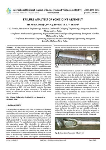
Fig-1: Yoke Joint and Transmission Drive Shaft (Midi712) The power transmission system of vehicles consists of several components which encounter unfortunate failures. These failures may be attributed to material faults, manufacturing and design faults, etc. During operation yoke should undergo for an infinite life with different loading. However, the highest stresses occur at the crack beginning location of the yoke. A possible surface fault leads to crack propagation at the highly stressed point. After a crack propagation period, the component undergoes fracture. A finite element stress analysis need to be carried out at the failure region to determine the stress distribution and possible design improvement.
Fig-2: Yoke Joint Assembly (Midi-712)
ISO 9001:2008 Certified Journal
Page 762