
International Research Journal of Engineering and Technology (IRJET) e-ISSN: 2395-0056
Volume: 11 Issue: 08 | Aug 2024 www.irjet.net p-ISSN: 2395-0072

International Research Journal of Engineering and Technology (IRJET) e-ISSN: 2395-0056
Volume: 11 Issue: 08 | Aug 2024 www.irjet.net p-ISSN: 2395-0072
Elango. S1 , Gomathi. A2
1Director – SHF Design Engineering Private Limited, Chennai, Tamilnadu, India
2Ph.D Research Scholar, Advanced Nanomaterials and Energy Research Laboratory, Department of Energy Science and Technology, Periyar University, Salem 636011, Tamilnadu, India
Abstract - The global society is rapidlyembracingrenewable energy sources and integrating them into the current system to mitigate the escalating environmental issues, including the surge in carbon dioxide emissions over the past century. Renewable energy sources provide significant capacity to mitigate carbon dioxide emissions as they virtually generate no carbon dioxide or other pollutants. However, these energy sources are typically affected by weather, geographical location, and other stochastic factors. The battery energy storage system used to store the energy generated by renewable energy sources (RESs) and then used as needed to mitigate the intermittent nature of these sources. The primary objective of the review article is to provide an overview of Battery Energy Storage System (BESS). The study provides precise estimation of the health indicators (HIs) ofthe battery, which is particularly significant inthe context ofManagingthe Battery System. This research offers a thorough examination and analysis of several health indicators for BESSs, utilizing a suitable categorization system based on major distinguishing features.
Key Words: (Energy storage, Battery, Health indicators, Temperature,Current,Voltage]
Battery energy storage systems (BESS) ensure a reliable energysupplyandareessentialforreducingexpensesand addressing the increasing need for sustainable energy solutions.Inadditiontoitsfunctionindrivingcostreduction anditscontributiontosatisfyingthegrowingneedforclean and reliable energy on a global scale, a BESS is becoming increasingly relevant as a result of its significance in the integrationofrenewableenergysources.Electricitystorage systems, also known as battery energy storage systems (BESS),areoftenstudiedandusedforarangeofpurposesin powergeneration,transmission,anddistribution,andthey also offer end-user benefits that make the investment worthwhile.Amongthemanyelectricgridservicesprovided bytheseinstallationsarevoltagesupport,frequencycontrol, smoothing and levelling of renewable energy, demand reduction, arbitration of renewable energy time-shift, and assistance with power dependability, power quality, and islanding operations. The BESS has also been used to increase reliability in distribution and transmission
networks, saving money compared to line upgrading projects.
Energy storage devices with the ability to recharge are widely utilised in various applications, including highcapacity electrical grids and portable low-energy gadgets. These devices effectively address the issue of renewable energy intermittency and allow for long-term reuse. The electricityoutputofwindandsolarfarmsisdeterminedby fluctuations in the weather, season, and time of day [1]. Recent developments in battery technology have also resultedinbetterenergystoragedensities,increasedcycle capabilities,increasedreliability,anddecreasedcosts.
Battery energy storage systems (BESSs) experience numerous charge and discharge cycles throughout their lifespan.Thebattery'slifespanisthemostcriticalfactorin the cost of BESS operation. The charging and discharging scheduleofabatterydeterminesthenumberoflifecyclesit cansustainthroughoutitslifespan.Thebatterylongevityis adverselyaffectedbythehighcurrentduringchargingand discharging operations. As they age, their performance deterioratesandtheirreliabilitybecomesuncertain.Battery ageing can be quantified by assessing battery health indicators, which in turn are utilised to calculate battery degeneration.
Withinthescopeofthisarticle,theconceptofbatteryenergy storage systems (BESS) and its applications in the power sector are discussed. The research investigates Health Indicators (HIs) and their Classification, which are indispensable instruments that are employed for the purpose of measuring and evaluating the overall health conditionofanindividualbatteryorgroupofbatteriesina BatteryEnergyStorageSystem(BESS).
Batteries are frequently employed as an energy storage technologywhenincorporatingrenewableresourcesintothe power grid. The compact size, high power and energy densities, and high round-trip efficiency of these batteries make them ideal for both distributed energy storage applicationsandlarge-scalestoragesystems.Thesesystems canbeinstalledatvariouslocationstoeffectivelymeetthe powergrid'srequirements.Batteryenergystoragesystems
International Research Journal of Engineering and Technology (IRJET) e-ISSN: 2395-0056
Volume: 11 Issue: 08 | Aug 2024 www.irjet.net p-ISSN: 2395-0072
(BESS)havethepotentialtoenhancesystemresponsiveness, reliability, and flexibility, while also reducing capital and operatingcostsforsuppliersandcustomers[2].
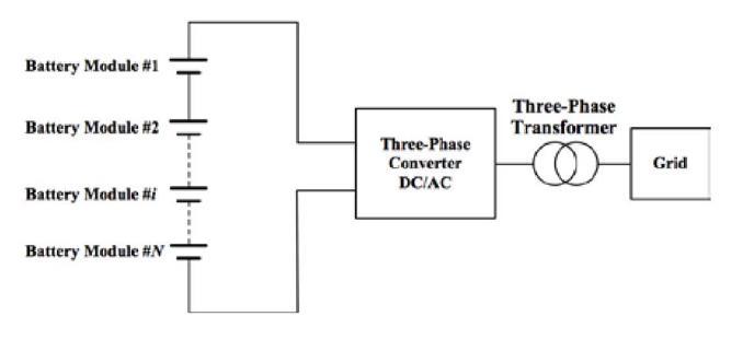
A comprehensive battery storage system primarily comprises battery modules, power electronic converters, and a battery management system. A battery module is composedofnumerouscellsthatareinterconnectedeither inseries,inparallel,orinbothconfigurations,dependingon thedesiredoutputvoltageandcapacity.Figure1[3]displays the system configuration of a traditional Battery Energy StorageSystem(BESS).
Inthisdesign,thebatterymodulesareinterconnectedina seriesconfigurationtocreateastring.Multiplestringscanbe connected in parallel fora BatteryEnergy StorageSystem (BESS). The battery modules are interconnected with a DC/ACconverterandsubsequentlylinkedtotheelectrical grid via a three-phase transformer. The DC/AC converter mightcomprisemanypowerselectronicconvertersthatare interconnected in parallel to minimize the dimensions of eachconverter.However,whenevaluatingreliability,allthe components are considered to be connected in series because they all need to function for the entire system to operate correctly. In the event of a failure in any of the components,theentiresystemwillfail.
Battery energy storage systems (BESS) in India have a combinedcapacityof219.1MWh,oraround111.7MW,asof March2024.Adding40MWinthefirstquarterof2024alone brings the total up to 120 MWh. Significant growth is anticipatedintheenergystoragecapacityofthenationinthe nextyears,whichisalreadygrowingataquickpace.Atotal of 9.7 GW of renewable energy projects in India will be operational by 2027, with an additional 1.6 GWh of standalonebatterystorageexpectedbythesameyear
BESScanbeusedinmanydifferentwaysinpowergridsto helpwithproblemslikeintegratinggreenenergy,keeping thegridstable,andmakingthewholesystemmoreresilient.
Astechnologyimproves,BESSislikelytobecomean even moreimportantpartofupdatingandimprovingpowerlines.
FollowingaretheListofBESSApplication
GridStabilization:
FrequencyRegulation
AncillaryServices
PowerQualityImprovement
LoadManagement
PeakShavingandLoadLeveling:
PeakDemandManagement
DemandResponse
RenewableEnergyIntegration:
IntermittencySmoothing
RenewableFirming
TransmissionandDistributionSupport:
CongestionManagement
VoltageSupport
GridResilience:
• BlackStartCapability
• EmergencyPowerBackup
GridPlanningandDeferral:
• CapacityDeferral
Health indicators are essential tools used to measureand assesstheoverall healthstatus ofindividual battery or group of batteries in Battery Energy Storage System (BESS). These indicators provide valuable information about various aspects of that can impact the performanceandlifespanofthebattery.Byquantifyingthe degradation,valuableinsightscanbegainedintothehealth andconditionofthebattery,furtherusageandmaintenance.
Onewaytomeasurebatterydegradationiswiththeuseof HealthIndicators(HIs)[4].Batteriesstateofhealth(SOH)is estimatedusingbelowparameters,
Thebattery'scapacitytoholdenergy
Itsabilitytodelivercurrent
Battery mechanical integrity and self-discharge stressdata
Theefficacyoftheelectrochemicalprocesscanbeevaluated by measuring HIs using a standardized set of parameters, including voltage, current, and temperature [5,6]. These
International Research Journal of Engineering and Technology (IRJET) e-ISSN: 2395-0056
Volume: 11 Issue: 08 | Aug 2024 www.irjet.net p-ISSN: 2395-0072
markersarethenemployedtomeasurethestateofhealth (SOH).
AcomprehensivecategorizationofHIsisexplainedbelow, distinguishingbetweenprimarilymeasuredandcalculated HIs as the main types. This classification provides a framework for understanding the different ways in which HIscanbedeterminedandevaluated.
6.1 MEASURED HEALTH INDICATORS
TheVoltageCurrentbasedmeasuredHIs
TheTemperaturebasedmeasuredHIs
6.2 CALCULATED HEALTH INDICATORS
TheVoltageandCurrentbasedtheCalculatedHIs
TheTemperaturebasedcalculatedHIs
TheVoltageandCurrentIntegralbasedCalculated HIs
TheTemperatureIntegralbasedcalculatedHIs
6.1.1 The Voltage and Current based Measured HIs
ThefollowingHIsarebasedonvoltageandcurrentandare partofthemeasuredHIS[7]
The Time interval for Charging at a Constant Currentfromadischargedconditionisdepictedand itisabbreviatedasCCCT.
The Constant Voltage Charge Time (CVCT) - The durationofchargingataconstantvoltagefollowing constant-currentcharging.
TimeofEqualCurrentDrop,orTECD,istheamount oftimeittakesforthechargingcurrenttodecrease bythesameamountduringseveralchargingcycles whilethevoltageremainsconstant.
Thetimeittakesforthevoltagetoincreasebythe same amount across numerous charging cycles whenusingaconstantcurrentchargeisknownas TEVR,orTimeofEqualVoltageRise.
VRET, Voltage Rise of Equal Time: with constantcurrent charging, the voltage increases at a consistentrateacrossseveralchargingcycles.
Current Drop of Equal Time (CDET) - constant voltageelectrostatictransfercurrentdeclineduring severalchargingcyclesofthesameduration.
Thetimeittakestodischargefromafullchargetoa discharge state at a constant current is known as theConstantCurrentDischargeTime(CCDT).
VoltageDropoverEqualTime(VDET):Thevoltage dropsoverseveraldischargecycleswithaconstant current.
Time of Equal Voltage Drop, or TEVD, is the durationofaconstant-currentdischargeinwhich thevoltagedropsbythesameamountthroughout eachdischargecycle.
InthemeasuredHIssegment,thetemperature-basedHIsare listedbelow[7,8]:
HCCCT and LCCCT stand for Highest & Lowest Constant Current Charge Temperatures, respectively: Over the charging interval with a steady current, the maximum and minimum temperaturesfound.
The two variablesthat makeup theHCT and LCT aretheHighest&Lowesttemperaturesthatwere recorded throughout the Charging period, respectively.
HT,LT:Highest&Lowesttemperature:Maximum and minimum temperatures during the charging anddischargingcycle.
TETR, or Time of Equal Temperature Rise, is the duration of repeated cycles of constant-current dischargewherethetemperaturerisesbythesame amount.
TRET,TemperatureRiseofEqualTime:therateof temperature increases during several cycles of constant-currentdischarge,measuredinintervals ofthesamelengthoftime.
The two variables that represent the Highest & Lowest values of Temperature throughout the ConstantVoltageChargingintervalareHCVCTand LCVCT,respectively.
ExtremelyHighandLowDischargeTemperatures (HDT and LDT, respectively): Extremely high and low temperatures recorded during the discharge interval
6.2.1
ThefollowingarethecomputedHIsdependingonvoltage andcurrent[9.10]:
RCCCV,ortheRatioofConstantCurrenttoConstant Voltage, refers to the proportion of time that is dedicated to maintaining a constant current comparedtomaintainingaconstantvoltage.
International Research Journal of Engineering and Technology (IRJET) e-ISSN: 2395-0056
Volume: 11 Issue: 08 | Aug 2024 www.irjet.net p-ISSN: 2395-0072
Attheconstantvoltagecharginginterval,theSlope oftheChargeCurrent(SCC)isdefinedasdI/dt.
Attheconstantcurrentcharginginterval,theslope ofthechargevoltage(SCC)isdV/dt.
SCC = dV/dt during the constant current discharging interval; SDV is the Slope of the DischargeVoltage.
6.2.2 The Temperature Integral based calculated HIs
InthesegmentofcomputedHIs,thetemperature-based HIsarelistedbelow[11,12,13]:
In the constant current discharging interval, the Slope of the Discharge Temperature (SDT) is definedasdT/dt
2. Voltage and current integral based HIs [ 16].
Mean Discharge Temperature (MDT): The Mean temperature during the timeframe of continuous currentdischarge.
MCT,orMeanChargingTemperature,istheaverage temperaturereadingforthewholechargingcycle.
The Mean Constant Current Charge Temperature (MCCCT) is the average temperature during the chargingtimethatisconstant-current.
MT,meantemperature:AnMCVCT'sMeanConstant Voltage Charge Temperature is the average value thethermalparametersmeasuredthroughoutthe wholechargingprocess.
6.2.3 The Voltage and Current Integral based Calculated HIs
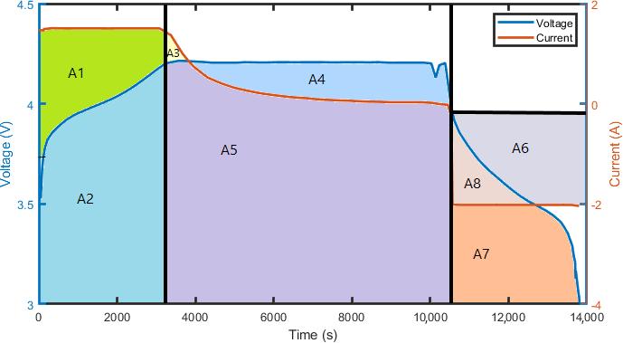
Theintegrationofthevoltageandcurrentgraphsyieldsthe areacomponents,asdepictedinFigure4.
FollowingistheIntegralHIsthataredependentonCurrent andVoltage[14,15]:
The area under the voltage in the interval of constant-currentchargingis representedasA2in Figure 2, which stands for Area under Constant CurrentChargeVoltage(ACCCV).
A1+A2inFigure2representstheAreaunderThe Current During the Interval of Constant Current Charging,whichisabbreviatedasACCCC.
TheAreaundertheVoltageoverthefullCharging intervalisrepresentedinFigure2asA2+A4+A5, whichisabbreviatedasACV.
ACC stands for Area under Charge Current and is shown in Figure 2 as A1 + A2 + A3 + A5. It encompassesthefullcharginginterval.
The Area under Voltage during the Constant CurrentDischargingintervalisshownasA7+A8in Figure 2, which stands for ADV and ACCDV. Since we are just interested in constant-current discharge,theseareidentical.
ADC and ACCDC, also known as Area under DischargeCurrentandAreaunderConstantCurrent DischargeCurrent,aredepictedinFigure2asA6+ A8
The area under the voltage during the interval of constant voltage charging is shown as A4 + A5 in Figure 2, which stands for Area under Constant VoltageChargingVoltage,orACVCV.
AreaunderConstantVoltageChargeCurrent(ACVCC):A3+ A5inFigure2illustratetheareaunderthecurrentduring theintervalofconstant-voltagecharging.
6.2.4 The Temperature Integral based calculated HIs
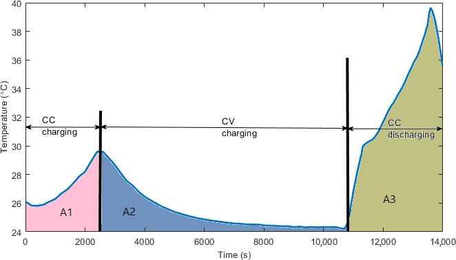
The determined heat indices(HIs),whichareobtained by integratingthetemperatureovertimetodeterminethearea underthetemperaturecurve,aredisplayedinFigure2and areasfollows[17-20]:
TheAreaunderthetemperatureduringtheTimeof Constant Current Charging, or ACCCT, as seen in figure3.
International Research Journal of Engineering and Technology (IRJET) e-ISSN: 2395-0056
Volume: 11 Issue: 08 | Aug 2024 www.irjet.net p-ISSN: 2395-0072
A1+A2inFigure3representstheAreaunderthe TemperatureforthefullCharginginterval,whichis abbreviatedasACT.discharging
ADT- Area under Discharge Temperature and ACCDT - Area under Constant Current Discharge Temperature: Area under temperature in the intervalofconstantcurrentdischarging,shownas A3 in Figure 3. These are the same, as constant currentisconsideredinthiscase.
ACVCT - Area under Constant Voltage Charge Temperature: Area under temperature in the intervalofconstantvoltagecharging,shownasA2 inFigure3.
Advancebitsofknowledgeintotheapplicationandeaseof use of HIs in real-world applications are variations as the battery ages. The operation unwavering quality and life expectancyofaBESSimprovewhencontrollingthecharging andreleasingdesignsbasedontheweakeningofthebattery wellbeingascomputedutilizingHIs.ThevarietyintheHIs withbatterycyclesshowsthattheHIsthataltermoreamid theafterwardlifeofthebatteryareespeciallymoreusefulin followingabattery’swellbeing.
7. CONCLUSIONS
Finally, Health Indicators (HIs) play a crucial role in integrating Battery Energy Storage Systems (BESS) to support the growing need for energy storage and to counteract the intermittent nature of renewable energy sources. an important part in keeping an eye on the batteries'SOHandpredictingtheirRUL,whichiscriticalfor makingsureBESSisreliableandefficient.
ContinuousCurrentChargeTime(CCCT),ConstantVoltage ChargeTime(CVCT),Time ofEqual Current Drop(TECD), andtemperature-basedindicatorslikeHighestContinuous CurrentChargeTemperature(HCCCT)andMeanDischarge
Temperature (MDT) are few of the HIs highlighted in the study. These indicators are great for monitoring battery healthsincetheyfollowcertainpatternsasthebatteryages, andseveralofthemaltersignificantlytowardstheendofthe battery'slife.
TheoperationaldependabilityandlifespanofBESScanbe greatlyenhancedbymanagingthecharginganddischarging patternsdependingonthedegradationofbatteryhealthas computed by HIs. As a result, managing and deploying batteryenergystoragesystemseffectivelyrequiresprecise assessment of battery health indicators and regular monitoringofthesystems.
1. Tian, J.; Xiong, R.; Shen, W. A review on state of health estimationforlithium-ionbatteriesinphotovoltaicsystems. ETransportation2019,2,100028.
2. N. Garimella and N.-K. C. Nair, “Assessment of battery energy storage systems for small-scale renewable energy integration,”inProc.IEEERegionConf.,Singapore,2009,pp. 1–6.
3.J. Schmutz, “Primary frequency control provided by battery,”Semesterthesis,EEHPowerSyst.Lab.,ETHZürich, SwissFed.Inst.Technol.,Zürich,Switzerland,Jun.2013.
4.Merrouche,W.;Trari,M.;Djellal,L.;Mammeri,M.;Tebibel, H.; Blaifi, S.; Chong, L.W.; Ould-amrouche, S.; Boussaha, B. Improved model and simulation tool for dynamic SOH estimation and life prediction of batteries used in PV systems.Simul.Model.Pract.Theory2022,119,102590.
5.Hu,X.;Che,Y.;Lin,X.;Onori,S.Batteryhealthprediction usingfusion-basedfeatureselectionandmachinelearning. IEEETrans.Transp.Electrif.2020,7,382–398.
6.Ma,Y.;Shan,C.;Gao,J.;Chen,H.Anovelmethodforstateof healthestimationoflithium-ionbatteriesbasedonimproved LSTM and health indicators extraction. Energy 2022, 251, 123973.
7.Saha,B.;Goebel,K.“BatteryDataSet”,NASAPrognostics Data Repository; NASA Ames Research Center: Mountain View,CA,USA,2007.
8.Li,Y.;Stroe,D.I.;Cheng,Y.;Sheng,H.;Sui,X.;Teodorescu,R. Onthefeatureselectionforbatterystateofhealthestimation based on charging–discharging profiles. J. Energy Storage 2021,33,102122.
9.Jiang,N.;Zhang,J.;Jiang,W.;Ren,Y.;Lin,J.;Khoo,E.;Song, Z. Driving behavior-guided battery health monitoring for electric vehicles using machine learning. arXiv 2023, arXiv:2309.14125.
International Research Journal of Engineering and Technology (IRJET) e-ISSN: 2395-0056
Volume: 11 Issue: 08 | Aug 2024 www.irjet.net p-ISSN: 2395-0072
10.Liu, Z.; Zhao, J.; Wang, H.; Yang, C. A New Lithium-Ion Battery SOH Estimation Method Based on an Indirect EnhancedHealthIndicatorandSupportVectorRegressionin PHMs.Energies2020,13,830.
11.Gou, B.; Xu, Y.; Feng, X. State-of-Health Estimation and Remaining-Useful-Life Prediction for Lithium-Ion Battery Using a Hybrid Data-Driven Method. IEEE Trans. Veh. Technol.2020,69,10854–10867.
12.Liu, D.; Zhou, J.; Liao, H.; Peng, Y.; Peng, X. A Health Indicator Extraction and Optimization Framework for Lithium-IonBatteryDegradationModelingandPrognostics. IEEETrans.Syst.Man,Cybern.Syst.2015,45,915–928.
13.Krupp, A.; Ferg, E.; Schuldt, F.; Derendorf, K.; Agert, C. IncrementalCapacityAnalysisasaStateofHealthEstimation Method for Lithium-Ion Battery Modules with SeriesConnectedCells.Batteries2021,7,2.
14.Pan,W.;Luo,X.;Zhu,M.;Ye,J.;Gong,L.;Qu,H.Ahealth indicatorextractionandoptimizationforcapacityestimation ofLi-ionbatteryusingincrementalcapacitycurves.J.Energy Storage2021,42,103072.
15.Yun, Z.; Qin, W. Remaining Useful Life Estimation of Lithium-IonBatteriesBasedonOptimalTimeSeriesHealth Indicator.IEEEAccess2020,8,55447–55461.
16.Sun,Y.;Hao,X.;Pecht,M.;Zhou,Y.Remainingusefullife predictionforlithium-ionbatteriesbasedonanintegrated healthindicator.Microelectron.Reliab.2018,88–90,1189–1194.
17.Wang, R.; Feng, H. Remaining useful life prediction of lithium-ion battery using a novel health indicator. Qual. Reliab.Eng.Int.2021,37,1232–1243.
18.Huang, Z.; Xu, F.; Yang, F. State of health prediction of lithium-ion batteries based on autoregression with exogenousvariablesmodel.Energy2023,262,125497.
19.Jia,J.;Liang,J.;Shi,Y.;Wen,J.;Pang,X.;Zeng,J.SOHand RULPredictionofLithium-IonBatteriesBasedonGaussian ProcessRegressionwithIndirectHealthIndicators.Energies 2020,13,375.
20.Nazaralizadeh,S.;Banerjee,P.;Srivastava,A.K.;Famouri, P. Battery Energy Storage Systems: A Review of Energy ManagementSystemsandHealthMetrics.Energies2024,17, 1250 https://doi.org/10.3390/en17051250

Elango Subramani is currently serving as the Director at SHF Design Engineering PrivateLimitedCompanyinIndia Having accumulated more than 18+ years of extensive international experience and a vast amount of knowledge in the power sector HeisCurrentlypursuingaDoctorof Philosophy at Periyar University. He had earnedaBachelorofEngineeringDegreein Electrical&ElectronicsEngineeringfrom Anna University, followed by an MBA Degree in Project Management from Alagappa University. Completed a Post Graduate degree in Electrical Safety and Safety Management from Annamalai University. He Obtained Lean Six Sigma Black Belt certification and also received accreditationasChartedEngineerfromthe InstitutionofEngineers

Gomathi. A, Ph. D Research Scholar, Advanced Nanomaterials and Energy Research Laboratory, Department of Energy Science and Technology, Periyar University, Salem 636011, India She has published 6+ research articles in SCI indexed International journal She has published book chapter in Taylor and Francis and also presented 10+ InternationalandNationalconferences