
International Research Journal of Engineering and Technology (IRJET) e-ISSN:2395-0056
Volume: 11 Issue: 07 | July 2024 www.irjet.net p-ISSN:2395-0072
International Research Journal of Engineering and Technology (IRJET) e-ISSN:2395-0056
Volume: 11 Issue: 07 | July 2024 www.irjet.net p-ISSN:2395-0072
Aanchal1, Anuj Verma Sir², Mohd Saqib Qadeer Sir³, Anshu⁴
¹Student Scholar, Civil Engg. Deptt. RIMT Bareilly.
²Asst. Professor &(HOD) of Civil Engg. Deptt. RIMT Bareilly
³Asst Professor of Civil Engg. Deptt. MIT Moradabad
⁴Student Scholar, Civil Engg. Deptt. MMMUT Gorakhpur.
Amethodusedforsoilstability,whenlandslidesareamajorproblem,isbuildingawallwithdirtandnails.Aslopecanalsobe strengthened and stabilised by using it. To strengthen the natural ground, the process known as "soil nailing" includes groutingmetalbars,sections,orsteelreinforcement(suchasnails)intothedrillholes.Itisatoptodownmethodofbuilding. Inordertostabiliseslopes,excavations, etc.,itisutilised.Toconstructretainingwallsincutapplications(top-downdesign), soilnailinghasbecomeincreasinglypopularintheUnitedStates.Currentstateoftheresistancefactorandsoilnaildesign.By utilising the Federal Highway Administration's (PHWA) most recent nail load and occupancy model, a generic approach for calibrating resistance factors for It is briefly presented the pull-out load and resistance factor design (LRFD) and the tensile failure internal limit conditions of soil nail walls. Resistance factor designs for the permanent soil wedge and the anchor's pullout limit site are calibrated against a large design space. For computing resistance factors, Simple models for artificial neuralnetworks(ANNs)havebeencreated.Thepaperalsodiscussesconcernsregardingtheimpactofoutliersindatasetsand potentialdependenciesbetweenvariablesthatmayhaveasignificantimpactonthecalibrationresults.
Keywords:limitsofinternalstability,tensileyieldingcapacity,Settingtheresistancefactor'scalibration,andtheloadfactor Indexoftargetreliability,ReinforcedSoilWalls,SteelReinforcement,andSoilNails.
Since the late 1960s, engineers and construction professionals in a number of nations, including the US, Europe, and Japan, have used the special efforts and benefits of soil nailing. Geotechnical engineering techniques such as foundation reinforcementofsoilhaveawiderangeofusesforstabilisingexcavationsandslopes.Advancedcompositematerialreinforced soil is made of dirt and reinforcement. The compressive and tensile strengths of this substance are comparable to those of reinforced cement concrete. Nature contains the fundamental concepts of soil reinforcement. In 1969, Vidal was the first to employ a cutting-edge method of soil fortification. According to Vidal's idea, the soil and the horizontal parts that provide frictional reinforcement. In 1986, retaining walls were built in France utilising this idea. Nowadays, developing nations frequentlyadoptslopereinforcementtechniques.Therehasbeensignificanttheoreticaldevelopmentinthefieldofreinforced soils.InarailroadwideningprojectinFrance,closetoVersailles,an18-meter-highsandbankwasstabilisedforthefirsttime. (Rabejac and Toudic, 1974) There has been significant theoretical development in the field of reinforced soils. France and otherEuropeancountrieshaveahigherprevalenceofsoilnailing.TheearthenwedgewallwasinitiallyutilisedinGermanyin 1975.
Over the past 25 years, reinforced soil (RS) walls have been used in India and are being used more frequently in the construction of bridges and roads. Modern materials and technology are required for these applications. Theoretical advancements, design methodologies, and experience acquired in lab settings, full-scale tests, and field applications in the behaviorof RS WallsinIndia andoverseashave enabledpractisingengineerstousetheirknowledgemorebroadly.Projects involvingroadsandbridgesusethistechnique.Thereleaseoftheserecommendations(hencereferredtoasthe"Guidelines") coveringdesignandconstructiontechniquesislongoverdue, Inordertobenefitbothnewandexistingusers,itisessentialto offer consistency in the design and philosophy used by different system manufacturers. It is believed that this must be
International Research Journal of Engineering and Technology (IRJET) e-ISSN:2395-0056
Volume: 11 Issue: 07 | July 2024 www.irjet.net p-ISSN:2395-0072
guaranteed. Minimum standards and criteria for material acceptance must be met in order to ensure address the longstandingdemandforIntherealmofroadwayandbridgeengineering,homogeneityinpartialloadfactorsandpartialmaterial safetyfactorsisimportant,aswellastoachieveadesignlifeof100years. (INDIAN ROAD CONGRESS 2014)
Design and implement of systems of systems for retaining soil and fill that direct to open areas. These rules apply to all bridges, flyovers, railway crossings, and high-fill retaining walls for road embankments. Benefits of resistant soil include increased power for carrying loads with lower compressibility in load. The recommendations do not cover the technical aspectsofsuchapplications.TheserecommendationsdonotincludethesupportforcarryingfromopenspansusingRSwalls. Theserequirementsdonotapplytoreinforcedsoilconstructionswithslopeangleslessthan70degreefromthehorizontal.
Theprocedurescopeincludes,butisnotrestrictedto:
(1) Thesoilusedinitsconstruction,thereinforcementstypeandqualities.
(2) Typesoffacing,fillandreinforcement.
(3) Materialevalution.
(4) Designtechniques.
(5) Extensivefabricationprocedurestomeetrequirements RSwall behavior andattributes. (INDIAN ROAD CONGRESS 2014)
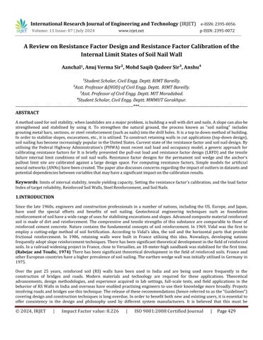
Accordingtotheidea behindsoilnailing,slopesandexcavationsarestabilisedfromtoptobottom.Soil-nailinteractionleads tothegenerationoftensiletensioninsoilnails,whichgivessoilnailstheirreinforcingeffectagainstgrounddeformation.The creationofaxialforce,whichisessentiallyatensionforce,iswherethemajorityofresistancesoriginate.Inthepast,bending andshearhavebeenthoughttocontributelittletoresistance.
© 2024, IRJET | Impact Factor value: 8.226 | ISO 9001:2008 Certified Journal | Page430
International Research Journal of Engineering and Technology (IRJET) e-ISSN:2395-0056
Volume: 11 Issue: 07 | July 2024 www.irjet.net p-ISSN:2395-0072
Aslopeorexcavationbecomesmorestableasaresultofsoilnailing.
a)Increasingboththeshearresistanceandtheusualforceinfluencingtheshearplane.Intheabrasivesoil,theplaneskidded.
b) In both cohesive and frictional soils, lowering the pushing force along the slip plane.Reinforcement is laid horizontally or parallel to a gradually slope in soil nailing. The direction of tensile stress to generate the maximum amount of tensile force (Arindam Dey 2015).
1.2 Types of soil nailing
Thefollowingaresomeofthedifferentkindsofsoilnailing:
a)Agroutedsoilnailisintroducedintotheholeusingeitherpressureorgravityafternailsareinitiallypositionedinthecentre ofthedrillhole.
b)Drivennail-Thesenailsaredrivenimmediatelyfollowingeachstageofexcavation.
c)JetGroutedNails:Thesecompositeinclusionsarecomposedofdirtthathasbeengroutedaroundasteelbarinthemiddle. Highfrequencynailsarethenputaftervibro-percussiondrivewithhighpressuregrout.
d)Nailsthatarelaunchedintotheground thistechniqueinvolvesrapidlyfiring nailsintotheearth.utilisingthelauncherfor compressedair.Thisapproachisquick,adaptable,andcost-effective.About320km/histhesettingspeedforthenails. 2015 (Arindam Dey).
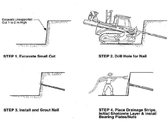
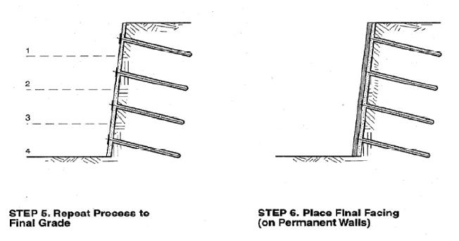
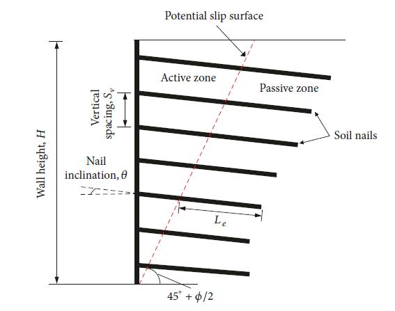
Fig2:Orderofconstructionforsoilnailing (Byrne et al., 1998)
International Research Journal of Engineering and Technology (IRJET) e-ISSN:2395-0056
Volume: 11 Issue: 07 | July 2024 www.irjet.net p-ISSN:2395-0072
1.3Main component or element of Soil Nail Wall
(a)ConnectivityElements
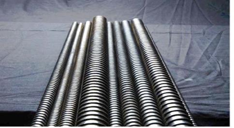
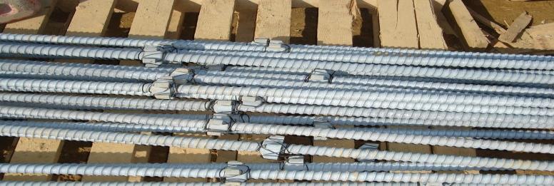
(b)ReinforceBars
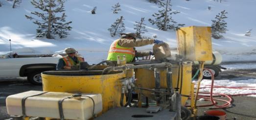
(c)Grout
(d)Centralizers
(e)Corrosionsecurity
(f)Drainagestructure
(g)Barrageface (Carlos A .Lazarte et al. 2015)
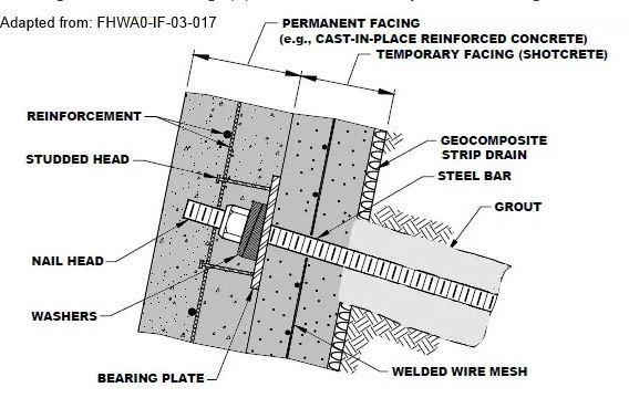
Thefollowingisadiagramofeverymajorcomponentofasoilnailwall.
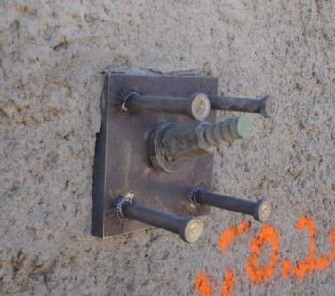
Solidtendoninaphotographthathasasteelplate,awasher,andnutstudsthatarenotheadedforattachmenttothe finalfacing.ThankstoDYWIDAG-SystemInternationalfortheimage. (Carlos A.Lazarte, 2015)
© 2024, IRJET | Impact Factor value: 8.226 | ISO 9001:2008 Certified Journal | Page432
International Research Journal of Engineering and Technology (IRJET) e-ISSN:2395-0056
Volume: 11 Issue: 07 | July 2024 www.irjet.net p-ISSN:2395-0072
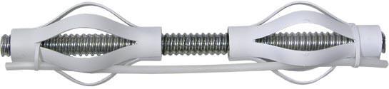
Fig3d:Picture:ThesolidbarisfastenedwithstandardPVCcentralizers.(Thecentralizerspacingshownissolelyfor demonstrationpurposes;largerspacingisactuallyemployed.)ThankstoWilliamsFormEngineeringCorp.forthephoto. (Carlos A.Lazarte, 2015)
StandardsteelcentralizerswerefittedtotheHBSNsintheimage.ImageprovidedbySchnabelEngineering (Carlos A.Lazarte, 2015)
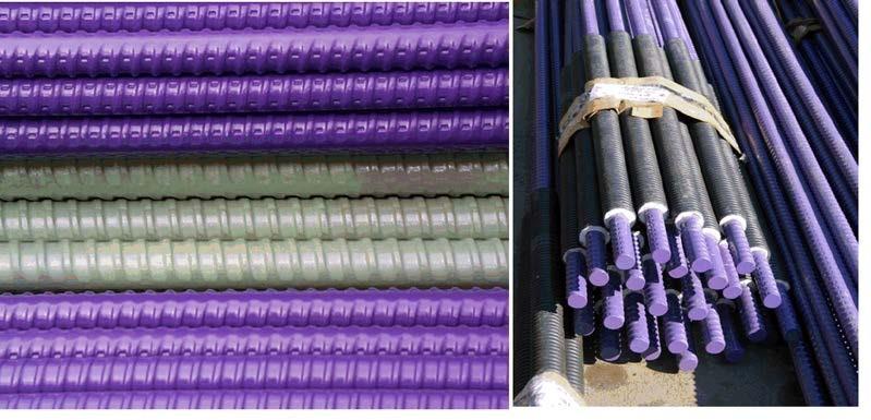
Fig3e:Photo:partialencapsulationbycorrugatedbark(right)andsolidtendonswithagreyorpurpleepoxycovering (left).ThankstoDYWIDAG-SystemsInternationalfortheimages (Carlos A.Lazarte, 2015)
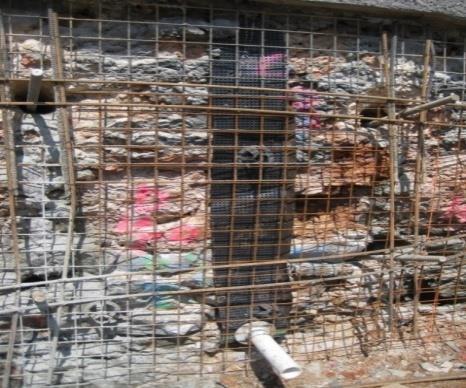
Fig3f: Solidtendonthathasbeenphoto-threadedwithasteelplate,awasher,andanut.studsthatarenotheadedfor attachmenttothefinalfacing.ThankstoDYWIDAG-SystemInternationalfortheimage. (Carlos A.Lazarte, 2015)
© 2024, IRJET | Impact Factor value: 8.226 | ISO 9001:2008 Certified Journal | Page433
International Research Journal of Engineering and Technology (IRJET) e-ISSN:2395-0056
Volume: 11 Issue: 07 | July 2024 www.irjet.net p-ISSN:2395-0072
1.4 Ground Condition
1.4.1 Suited soil
a)Remainingdirtandwornrocks
b)Stiffcohesivesoilsthatareresistanttocreepdistortion,suchasclaysiltandothersoiltypes.
c)Sandandgravelthatisdenseandhassomeadhesivequalities.
d)Theelevationofapieceoflandabovethegroundwatertable.
1.4.2 Non -Suited
a)Becausetheydon’thaveenoughtimetostandupbeforenailinginstallation,theyshoulduseloose,fine-grainedsand.
b)Soilswithhighmoisturecontentordamppocketsbecausetheycompromisestability.
c)Excessiveloadsmustbebornebysoilsbecauseoftheirfrostsensitivityandexpansivecharacteristics.
d)Rocksthatareseverelyfracturedandhavevoidsoropenjointsbecausetogroutingissues.
Tosupportexcavationinsoilorsoft,wornrock,powerful,inertcomponentscalledsoilwedgesaredrilledandgrouted:
Stresses generated from soil or weathered rock mass deformation contribute primarily to the stability of earthresistantstructures.
Use shear stress (also known as bond stress) along the grout-ground interface to transfer tensile loads to the surroundingground.
Createresistancesthatcanbeanticipatedusingrecognizeddesignprocesses.
To guarantee adequate, long-term functionality of the system, corrosion prevention must be long-lasting and provable.
Interactstructurallywiththeexcavator’sfrontloadtestingisdoneusingtherecommendedprocedures.
As per established protocols, routine manufacturing is submitted to QC/QA.(Carlos A. Lazarte 2015, Sabatini, P.J., Pass, D.G. 1999, Sabatini, P.J., Bachus 2002, Sabatini, P.J., Tanyu 2005).
International Research Journal of Engineering and Technology (IRJET) e-ISSN:2395-0056
Volume: 11 Issue: 07 | July 2024 www.irjet.net p-ISSN:2395-0072
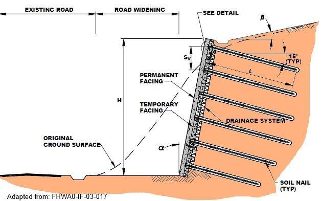
Fig4:Typicalsoilnailwallarrangement(https://www.deepexcavation.com/en/products/snail-plus-soil-nailingsoftware/design-of-soil-nail-walls-information,2022)
A dirt nail wall's general construction system entails the following:
a) Divingfortheinitialnails
b) Installinginitial
c) Ifnecessary,addwiremeshorotherreinforcementtothefirstlayerofshotcretethatisputoverthesoil.
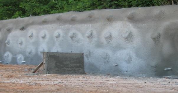
d) Asoilnailheadplate'ssmoke.
e) Shotcreteconstructioninasecondstage.
f) Toreachthenextearthwedge'slevel,descend,addsomeshotcreteandanotherwedge,etc.
g) Usingstepsc)throughf)repeatedlyupuntilthelastlevelofexcavationisreach.
h) Buildmorepermanentfacingsifnecessary.
Inconstruction,drainagefiltersandpipelinesarefrequentlyinstalled.
Typicalsoil-nailwallcrosssection
(From U.S. Practice )(https://www.deepexcavation.com/en/products/snail-plus-soil-nailing-software/design-of-soil-nailwalls-information,2022)
© 2024, IRJET | Impact Factor value: 8.226 | ISO 9001:2008 Certified Journal | Page435
International Research Journal of Engineering and Technology (IRJET) e-ISSN:2395-0056
Volume: 11 Issue: 07 | July 2024 www.irjet.net p-ISSN:2395-0072
Thestructureinthispaperenablesmanualusersto:
CheckstructuralcapacityusingAASHTOloadfactorvalues“LRFDBridgeDesignSpecification”(2014)intypicalLRFD equationstyle.
Design soil nail walls using a specially created limit-equilibrium, conventional acceptable stress design (ASD) based computerprogrammetoverifythesupposedmanyinsoilnailwallmechanism.
ConsistofresistancefactorsthatareassociatedtotheweightfactorinAASHTO(2014)toproducedesignsthatareas conservative as or somewhat more so than designs created using ASD based safety factors (FS) as described into earliereditionofthisguide.
Include associated permissible boundary states and corresponding resistance components for further earth-retaining structures, compatible with, but not identical to those defined in AASHTO (2014), and that are rounded to the closest 0.05. (Carlos A .Lazarte et al. 2015)Includeresistancecharacteristicsthatarerelevanttothebareminimumfrequencyneeded for verificationtesting.
a) Similar to artificial design ,LRFD focus on “limit state design”, where soundness or crash situation is taken into account.
b) Factoredloadfactoredtoughness,oftenknownas.
c) Loadfactorsareundercontrolandincreaseloads,whilstresistance factorsdecreasetoughness.
d) Loadandloadfactor,resistanceandresistancefactors.(J.S. Arora 2022)
4.1 The ASD Method (Allowable Stress Design)
Engineeringdesignuncertaintyhastypicallybeenacceptablestressdesign(ASD)factorsofsafety(FS).Theallowed“stresses” (or,moregenerally,resistance)ofstructuralcomponentsaredeterminedusingtheASDapproachbydividingthecomponents ultimatestrengthbyFS.ThegeneraldesignrequirementfortheASDtechniqueis:-
Where:-
∑Qi istheoutcomeofeveryjointloadoperatingonacertainstructuralcomponentunderaparticularfailurescenario.
Rall isthemaximumstressthatcanbeplacedonthatstructuralelement.
Rn isthemaximumorultimatestrengthofastructuralcomponent.
FSistheappliedsafetyfactortothatmaximumresistance.
4.2 The LRFD Method (Load & Resistance Factor Design)
IntheAASHTOLRFDBridgeintegratedLRFDapproach
Fourcategoriesoflimitstatesaredefinedindesignspecifications:
i)Statesofstrengthlimlits
ii)Statesofextremeevents
International Research Journal of Engineering and Technology (IRJET) e-ISSN:2395-0056
Volume: 11 Issue: 07 | July 2024 www.irjet.net p-ISSN:2395-0072
iii)Statesofservicelimits
iv)Statesfatiguelimits
Strength bound state are those that pertain to the strength (usually known as nominal resistance in the LRFD standard, as definelater)andstabilityofstructuralelementsoverthedesignlifeoftheconstruction.Generallyspeakingadesignequation canbewrittenasfollowsforeachstrengthlimitstate.
Where:-
Rnisnominalstruggleofaspecificstructuralelementtotheassumedstrengthlimitcondition
ØisaRn–relatednondimensionalresistancefactor
Qiisthei-thweighttypeinvolvedinthisboundsituation
γiis aQi-relatednon-dimensionalloadfactor
ηiisfactorforweightadjustment
Nisthevarietyofloadtypemustbetakenintoaccountatthelimitstate.
The tendons' yield strength, the earth's shear strength, the addition resistance of the soil nails, and numerous facing resistances are examples of nominal resistances. The reader should be aware that the terms power (usually used in ASD platforms) and nominal resistance (often used in LRFD platforms) are equal in order to maintain consistency. TheaveragenominalresistivityofthesoilandothernaturallyoccurringmaterialsusedinLRFDplatforms.Themeasurement ofclayresistanceisdoneinthegroundorinalab. (AASTHO 2014, Carlos A. Lazarte et al. 2015)
Thekeystepsforbuildinganearthenwedgewallareasfollows: (FHWA-NHI-14-007-2015)
1) Digger
2) Nail-holedrilling
3) Settingupnailsandgrouting
4) Settingupastripdrain
5) Thecreationofnewlevels
6) Constructionoffinalfacing. (Prashant C.Ramteke1,2* et al. 2022, FHWA. 2015)
6.1 Resistance factor:
There are numerous ways to check for resistance element. The most complex calibration methods rely on reliable statistical dataandusetherightstatisticalmethods,andproduceasystem-widelevelofreliabilitythatisacceptable.However,asstated in NCHRP Report 701, there are a number of obstacles to creating a uniform and comprehensive database for soil nails. (Lazarte 2011)
In that study the record of soil nail load testing was used to adjust the resistance factor for soil nail pull out. Data inconsistencies, a lack of information about the installation processes for soil wedges poor load test paperwork and other shortcomingsintheloadtestingwerefound.
International Research Journal of Engineering and Technology (IRJET) e-ISSN:2395-0056
Most importantly, none of the load tests applied enough pressure to maximise the test fingernail pullout resistance. Due to theseresistancefactorsbasedonreliabilitywasachieved. (Carlos A.Lazarte et al. 2015)
6.2 Load Combinations
It is necessary for structural design to take into account the immediate incidence of several consignment type in load combination.Thefollowingloadcombinationsarefrequentlytakenintoaccountforclaywedgedesigninpublicroadprojects usingtheLRFDstructure
StateofrepairLimit
StageIpowerLimit
Extreme-EvenLimitStateI(includingtheearthquakeload)
6.2.1 Load Factors:
Therearepermanenttransitoryand peak incidentloadsamongtheloadcombinationslistedabove. Theseloadsassigned loadfactorsare:
Deadloadsfromstructuralelementsandnon-structuralattachments(DC)
Deadloadsfromwornsurfaceandutilities(DW),whilesustainingaconnectionabutmentortheroad;anddeadloads fromutilities.
Verticalforcesbroughtonbythedeadloadfromearthfill(EV)
Earthpressureload(EH)
Earthsurchargeload(ES) (AASTHO 2014, Carlos A. Lazarte et al. 2015)
6.3. BENDING MECHANISMS:
Thefollowingformulasforreinforcedconcretedesignareusedtoestimatethebendingresistances
Volume: 11 Issue: 07 | July 2024 www.irjet.net p-ISSN:2395-0072 © 2024, IRJET | Impact Factor value: 8.226 | ISO 9001:2008 Certified Journal | Page438
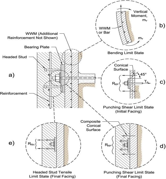
Fig6:Limitthedirtnailwall'ssides.thetensionoftheheadedstud;thetendencyofafacingsegment;thepunchshearinthe initialopposite;thepunchshearinthefinalfacing;and(a)atypicalfacingscheme.fromModifiedafterLazarte ,2011(CarlosA.Lazarte,2015)
International Research Journal of Engineering and Technology (IRJET) e-ISSN:2395-0056
For the initial face, a normalised section of reinforced shotcrete or thick concrete (or thick hf for the final facing) is used schematicallydepictedin thefigure, with the reinforcementinthecentreofthesection. WWMalone or in combination with rebarcanbeusedasreinforcement.Theheightofhi(orhf)willberepresentedbythethickness.
Accordingtothereinforcedconcretedesign,asimilarbeamcanwithstandpurebending.Thefigureshowtheinstantper unit length(mv)rotatingalongahorizontalaxis. (Carlos A. Lazarte et al. 2015)
7. FAILURE MADE OF SOIL NAILING:
Followingarethethreepossiblecausesofsoilnailingfailure:
Volume: 11 Issue: 07 | July 2024 www.irjet.net p-ISSN:2395-0072 © 2024, IRJET | Impact Factor value: 8.226 | ISO 9001:2008 Certified Journal | Page439
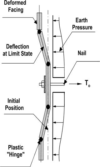
nailforceinfacing.ModifiedafterLazarte(2011). (Carlos A.Lazarte, 2015)
a) A face failure:- Whenasoilnailwallwithlongnailsthathavebothhighandlowtensilestrengthscollapses,itresults inthistypeoffailure.whenafailureunderminestheactiveregion'sabilityto remainstable.,thestrengthofthehead willemerge.
b) Pull-out failure:- This occurs when the strength and tensile capacity of the soil nail are high, as well as restricted penetration into the passive withstand area. The force produced by the nails in the active zone will depend on the lengthofthereinforcementinthepassivezone,andthisforceisexpressedas.
Q = πqDDH
DDH stands for the effective diameter of the nail hole, Q for the mobilised pull-out per unit length, and Q for the mobilisedshearstressactingonthevicinityofthesoilnail.Byconsideraonlynailsectionthatissubjecttoatensile strength,T0,atonestopandapplyingabalanceofforcesalongthedegreeofdifferencelengthsection(Dx)ofthenail, itispossibletodeterminethetensileforcefromtheinterfaceshearstress:
dT=p qDDHdx = Qdx
Theanticipatedtotalpull-outforce(F)isgivenasfollowsifthepassiveregion'ssoilnail'simplantedlengthisLP:
F = Q.LP
c) Nail tendon Failure:- Failure of the nail tendon happens when there is enough nail length but a little amount of tensilestress.(Arindam Dey 2015)
International Research Journal of Engineering and Technology (IRJET) e-ISSN:2395-0056
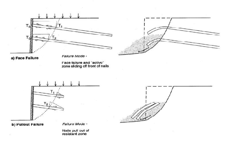
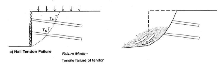
Fig8:-Potentialcausesofsoilnailwallsfailing (Byrne et al., 1998)
The suggested closed-form result is used to calculate the resistance factor (2017) by Bathurst et al. The approach bias statistics the relationship between the nominal load and resistance terms as well asthe uncertainty in the nominal load and resistance terms' amounts for various combinations of load and resistance models, method bias values, and dependence between nominal standards are all taken into consideration in the method for calibrating resistance factors. Closed-form solutions also offer the advantage of simplifying the calculation of resistance factors using an Excel spreadsheet and the evaluationofthepressureofmethodbiasandinputlimitationvariabilityonthefinalresistancefactorvalues. ( Lazarte et al. 2015; Lin et al.2017a, b; GEO 2008 )Soil wedges are passive additions that increase the soil's ability to withstand shear. Zonesthatareactiveandpassivecanbeseeninthesoil-nailsystem.Theactivezonebecomesdistortedduringslopecollapse, whereby the soil nails positioned across the slip plane experience axial displacement. The soil wedge experiences tensile pressures as a result. a passive zone that prevents the active region's deformation. This tension causes an increase in force reducesthedrivingshearforceandthenormalforceonthefalljet. Therubbingofdirtandnailsontheslopeispreventedby claynailsinsertedinthepassivezone (Arindam Dey 2015)
8.1 LIMITATIONS
1. Because this method creates dynamic friction resistance with ground deformation, it cannot be employed in situations wherestrictdistortioncontrolisnecessary.
2.Forsoilnailing,sandandgravelmightnotbesuitable.
3.Areaswithhighwatertablesshouldnotbeused.
4.Extremelyhighsoilnaildensitiesmaybenecessaryforsoilnailinginsoilswithverylowshearstrengths.
Volume: 11 Issue: 07 | July 2024 www.irjet.net p-ISSN:2395-0072 © 2024, IRJET | Impact Factor value: 8.226 | ISO 9001:2008 Certified Journal | Page440
International Research Journal of Engineering and Technology (IRJET) e-ISSN:2395-0056
5.Forlong-term,permanentapplications,soilnailingisnotadvisedinexpansivesoilsandsensitivesoils.(Arindam Dey 2015, Piyush Sharma)
Thefollowingaresomebenefitsofadirtnailwall:
•Simpleadjustmentofsoilnailswhiledealingwithpilesandotherundergroundobstructions.
•Lessenstheimpactontheenvironmentandthedisruptionoftraffic.
•Thequickconstructioncouldbetoblame.
•Affordableatdifficult-to-reachplacesanddistantregions.
•Successfulinrestoringlandslidesthataren'tontheslidetrail.
•Fairlyadaptable,allowingforbothlargeaggregateanddifferentialmovements.
•Itfunctionsflawlesslyunderearthquakeloading.
Duetothegreaterredundancythangroundanchors,apassivesystemwithrelativelymoderatetensilestressesexertedbythe reinforcing elements, a well-established construction quality assurance programme, and the higher density of reinforcing componentsperunitarea.
•Moreaffordablethanconventionalearthretainingsystemsforlengthsofover15feet.
•Groundanchorsaretypicallyequallyascost-effectiveaswalls,ifnotmoreso.
9. FUTURE SCOPE:
Soil nailing is most commonly used for new building projects, including foundation excavation and slope stabilisation, both temporarily and permanently. Given the current economic trends, it is most likely that this industry in India will be where nailing finds its most widespread use. The technology is equally useful for a variety of corrective tasks. It is envisioned that practical research collaboration between industry, universities, and government will support thedevelopment oftechnology inIndia,muchlikeitdoesindevelopednationslikeGermany,France,ItismostlikelythatthisindustryinIndiawillbewhere nailingfindsitsmostwidespreaduse. (Piyush Sharma)
10.
1)Anall-inclusivetechniquefor this work presents resistancefactorcalibration fornail pulloutand tensile yieldstrength of steelbar(nailtendon)limitstates.
2) Resistance factors were createdutilising a number of loadand resistance model combinations fortheload and resistance factordesignofnailpulloutandtensileyieldstrengthlimitstates.
3)Forthe twocases,the resistorswerecalibratedfor target reliabilityindicesof2.33to3.54andloadfactors of1to 2.One method involves directly estimating employing the Hong Kong CDG and CDV soil characteristic data, the uncertainty in the nominal load and resistance values at the time of design. Thesecondmethod,whichwasfoundedontheideaofunderstandinglevel,employedamoreexpansivedefinitionofnominal loadandthecoefficientofvariationofnominalresistance
4) The calibrated resistance factors for the nail pullout limit state utilising the current load and resistance model were typically greater than 1.00 due to the model's inherent conservatism. The resistance factors were ascertained using the
Volume: 11 Issue: 07 | July 2024 www.irjet.net p-ISSN:2395-0072 © 2024, IRJET | Impact Factor value: 8.226 | ISO 9001:2008 Certified Journal | Page441
International Research Journal of Engineering and Technology (IRJET) e-ISSN:2395-0056
Volume: 11 Issue: 07 | July 2024 www.irjet.net p-ISSN:2395-0072
modified model.Forthe nail tensile yieldstrengthlimit condition,the expected resistancefactors wereall lessthan1.00.An example design for soil nails supporting a 10-metre-high wall in Hong Kong CDG soil was used to show how calibrated resistancefactorsareimplementedintheLRFDframeworkusingvariouscombinationsofloadandresistancemodels.
5) The resistance factors in the example design were set to 1.00 in order to meet the supplies of the LRFD devise code. The planoutcomesshowedthat theenhancedloadandresistancemodel,combinedwith longerlargelylengths ofsoil spikesand minorsteelbardiameters,providedbettersolutionsthantheexistingloadandresistancemodel.
6) This stresses the benefit of refining weight and resistance models for soil nail wall inside stability devise by empirical modification, as established in other related works. LRFD is a subset of reliability theory-based analysis and design, as described in the introduction. LRFD provides the designer with straightforward boundary-state equations for foundation designissues,includingsoil-structureinteraction.
7)Sincethetruemarginofsafetyisunknown,therearefewerpossibilitiesforthedesignertofurtheroptimiseplanchoicesor possiblyadoptabetterboundaryofsecuritythanthatsuggestedbythislearnortheoneusedtodetermineresistancefactors. Thesamedata,model,andexamplefromthisstudywereusedbyLynn,anLRFDcodewriter,toofferareliability-baseddevise (RBD)advancefordirtnailwalls.
8)Eventhoughthisresearchfocuseson theresistanceside,LRFDcalibrationwasperformedusingHongKongsoilnaildata; however,load-sidemodelsaremorebroadlyapplicable.
9)Asaresult,theresistancefactorsfoundforCase2inthisstudymaybeusedasdefaultvaluesforinitialdesignpurposesif the designer is confident that the soil type, nail type, and installation method will be reasonably similar for subsequent projects.
10) The similar is true of the determined tensile bound state resistance factors in this article. In a perfect world, load and resistancebiasdatafromthesametypeofstructureandforthesamegroundconditionswouldbeusedtocalibrateanybasic soil-structure boundary states. To the authors' knowledge, there is currently no information available regarding the contributions from load and resistance to the two limit states examined in this study. The LRFD calibration approach suggestedinthis researchcanbeused witha varietyof nail andsoil typecombinationsif matchingloadand resistancedata aresupplied.
[1]. C.A. Lazarte , G. B. Baecher, J. L. Withiam, New Directions in LRFD for soil nailing design and specification.LSD [2003: International Workshop on limitstate design in Geotechnical engineeringpractice phoon ,Honjo& Gilbert (eds) ©2003 WorldScientificPublishingCompany.
[2]. PeiyuanLin1 andRichardJ.Bathurst,M.ASCE2 CalibrationofResistanceFactorfor LoadandResistanceFactor designof InternalLimitstatesofsoilnailWall,.ASCEJ.Geotech.Geoenviron.Engg.,2019,145(1):04018100.
[3]. HuiHu&PeiyuanLinAnalysisofresistancefactorforLRFDofSoilNailpulloutLimitStateUsingdefaultFHWAloadAnd resistancemodels,MarineGeoresourcesAndGeotechnology,Volume38,2020-Issue3.
[4]. RichardJ.Bathurst,TonyM.Allen,AndrzejS.Nowak, CallibrationconceptsforloadandresistanceFactordesign(LRFD)of reinforced soil Walls,Canadian Geotechnical journaloctober2008,https://www.researchgate.net/publication/233661685.
[5]. Prashant C.Ramteke1,2*,Anil kumar sahu1,Slope Stability Analusis of Soil nailed Structure by using ASDAnd LRFD Methods,internationalAdvancedresearchJournalinScienceEngineeringandTechnologyVol.9,Issue2February2022
International Research Journal of Engineering and Technology (IRJET) e-ISSN:2395-0056
Volume: 11 Issue: 07 | July 2024 www.irjet.net p-ISSN:2395-0072
[6]. CarlosA.Lazarte,PE,PhD,GE;HelenRobinson,PE;Jesús E.Gómez,PhD,PE;AndrewBaxter,PE,PG;AllenCadden,PE*; Ryan Berg, PE†, GEOTECHNICAL ENGINEERING CIRCULAR NO. 7 SOIL NAIL WALLS - REFERENCE MANUAL, National HighwayInstitute,U.S.DepartmentofTransportationFederalHighwayAdministration,Washington,DC20590(2015).
[7]. GuidelineforDesignandconstructionofreinforcedsoilwalls,INDIANROADCONGRESS2014.
[8]. StructuralDesignII,J.S.Arora/Q.Wang,LoadandResistFactor.doc(2022).
[9]. Huifen Liu,1Liansheng Tang,1,2 and Peiyuan Lin3, Maximum Likelihood Estimation of Model Uncertainty in Predicting Soil Nail Loads Using Default and Modified FHWA Simplified Methods, Hindawi Mathematical Problems in Engineering Volume2017,ArticleID7901918,14pageshttps://doi.org/10.1155/2017/7901918
[10].(https://www.deepexcavation.com/en/products/snail-plus-soil-nailing-software/design-of-soil-nail-walls-information , 2022),DesignofSoilNailWalls-Information
[11].PiyushSharma,THEORETICALANALYSISOFSOILNAILING:DESIGN,PERFORMANCEANDFUTUREASPECTS
[12].(https://www.researchgate.net/publication/286447893_THEORETICAL_ANALYSIS_OF_SOIL_NAILING_DESIGN_PERFOR MANCE_AND_FUTURE_ASPECTS)
[13].CaltransGeotechnicalManual,January2021.
[14].ArindamDey,IssuesandAspectsofSoilNailing,QIP-STConChallengesandRecentAdvancesinGeotechnicalEngineering ResearchandPracticesIITGuwahati2015.
[15].Lazarte, C.A. (2011). “Proposed Specifications for LRFD Soil-Nailing Design and Construction,” NCHRP Report 701, TransportationResearchBoard,Washington,DC.
[16].AASHTO (2014). “LRFD Bridge Design Specifications,” 7th Edition, American Association of State Highway and TransportationOfficials,Washington,DC.
[17].Byrne, R. J., Cotton, D., Porterfield, J., Wolschlag, C. and Ueblacker, G. (1998) “Soil Manual for design and construction monitoringofsoilnailwall”ManualoftheFederalHighwayAdministrationDivision,No.FHWA0-SA-96-069R.
[18].Bathurst, R. J., and S. Javankhoshdel. 2017. “Influence of model type, bias and input parameter variability on reliability analysis for simple limit states in clay–structure interaction problems.” Georisk 11 (1): 42–54. https://doi.org/10.1080/17499518.2016.1154160
[19].GEO (Geotechnical Engineering Office). 2008. Geoguide 7: Guide to soil nail design and construction. GEO Rep. No. 197. Hong Kong: GEO, Civil Engineering and Development Dept., The Government of the Hong Kong Special Administrative Region.
[20].CSA (Canadian Standards Association). 2019. Canadian highway bridge design code. 12th ed. CAN/CSA-S6-14. Mississauga,ON,Canada:CSA.
[21].Lazarte,C.A.,H.Robinson,J.E.G´omez,A.Baxter,A. Cadden,andR.Berg.2015.GeotechnicalengineeringcircularNo.7: Soilnailwalls,Referencemanual.USDepartmentofTransportationPublicationNo.FHWA-NHI-14-007.Washington,DC: FHWA.
[22].Lin, P., R. J. Bathurst, S. Javankhoshdel, and J. Liu. 2017a. “Statistical analysis of the effective stress method and modifications for prediction of ultimate bond strength of soil nails.” ActaGeotech. 12 (1): 171 182. https://doi.org/10.1007/s11440-016-0477-1
© 2024, IRJET | Impact Factor value: 8.226 | ISO 9001:2008 Certified Journal | Page443
International Research Journal of Engineering and Technology (IRJET) e-ISSN:2395-0056
Volume: 11 Issue: 07 | July 2024 www.irjet.net p-ISSN:2395-0072
[23].Lin, P., R. J. Bathurst, and J. Liu. 2017b. “Statistical evaluation of the FHWA simplified method and modifications for predicting soil nail loads.” ASCE J. Geotech. Geoenviron. Eng. 143 (3): 04016107.https://doi.org/10.1061/(ASCE)GT.1943-5606.0001614
[24].Lin, P., and R. J. Bathurst. 2018b. “Reliability-based internal limit states analysis and design of soil nails using different load and resistance models.”ASCE J. Geotech. Geoenviron. Eng. 144 (5): 04018022. https://doi.org/10.1061/(ASCE)GT.1943-5606.0001862
[25].Rabejac.S,andToudic.P,“ConstructionofaretainingwallbetweenVersailles-ChantiersandVersailles-Matelots”,Revue généraledescheminsdefer,Frenchrailwayreviewno.93,pp.232–237,1974.
[26].Stocker.M,-F,Korber.G,-W,Gässler.G,andGudehus.G,“SoilNailing,”inInternationalConferenceonSoil Reinforcement I,Paris,France,Vol.2,pp.469-474,1979.
[27].Stoker. M, Korber. G, Gassler. G, and Gudehus. G, Soil nailing.International Conference on Soil Reinforcement.Paris, France,Vol.2,p.469–474,1979.
[28].Sabatini, P.J., Pass, D.G., and Bachus, R.C. (1999). “Ground Anchors and Anchored Systems,” Geotechnical Engineering CircularNo.4,ReportNo.FHWA-IF-99-015,FederalHighwayAdministration,Washington,DC.,281p.
[29].Sabatini, P.J.,Bachus,R.C.,Mayne,P.W.,Schneider,J.A., andZettler,T.E.(2002).“Soil andRock Properties,”Geotechnical EngineeringCircularNo.5,ReportNo.FHWA-IF-02-034,FederalHighwayAdministration,Washington,DC.
[30].Sabatini, P.J., Tanyu, B., Armour, T., Groneck, P., and Keeley, J. (2005). “Micropile Design and Construction. Reference labouring for NHI Course 132078,” Report No. FHWA-NHI-05-039, Federal Highway Administration, Publication, Washington,DC.
[31]. FHWA.2015,GeotechnicalengineeringcircularNo.7soilnailwalls.Referencemanual,FederalHighwayAdministration, Washington,D.C.ReportFHWA0-IF-03-07,2015.
[32].Fenton,G.A.,F.Naghibi, D. Dundas,R.J.Bathurst,and D.V.Griffiths.2016. “Reliability-basedgeotechnical designin the 2014Canadianhighwaybridgedesigncode.”Can.Geotech.J.53(2):236–251. https://doi.org/10.1139/cgj-2015-0158
© 2024, IRJET | Impact Factor value: 8.226 | ISO 9001:2008 Certified Journal | Page444