
Volume: 11 Issue: 06 | Jun 2024 www.irjet.net
Volume: 11 Issue: 06 | Jun 2024 www.irjet.net
Nayana N1 , L.Govindaraju2
1P.GStudent, Department of Civil Engineering ,U.V.C.E, Bangalore University,Bengaluru
2Professor,Department of Civil Engineering,U.V.C.E,Bangalore University,Bengaluru
Abstract - As a vital infrastructure, elevated water tanksneed to be built to withstand all the forces expected to act during their life time. An elevated water tank attracts high lateral loads due to the huge mass concentrated at high elevation. The dynamic interaction between an elevated water tank and the underlying soil, especially in earthquake- prone regions, is a major factor that significantly influences the seismic performance of the water tank. In earthquake- resistant building designs, the inclusion of Soil-Structure Interaction (SSI) effects in the analysis is crucial for obtaining realistic performance of water tank during seismic events.
Water tanks situated on sloping ground face heightened vulnerability to earthquakes, primarily due to irregularities in both plan and elevation. But manywater tanks are routinely analyzed under earthquakeloadings without accounting for Soil-Structure Interaction (SSI). From a practical standpoint, thisapproach is strongly discouraged, emphasizing the necessity of considering Soil-Structure Interaction (SSI) for a comprehensive and accurate seismic assessmentofwatertanks
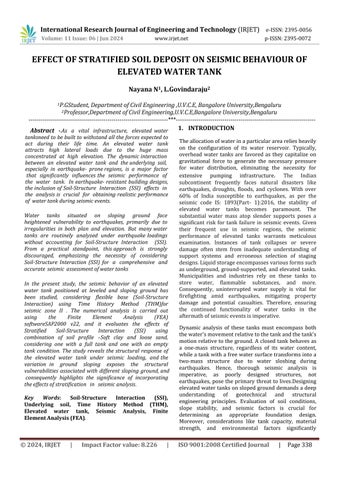
In the present study, the seismic behavior of an elevated water tank positioned at leveled and sloping ground has been studied, considering flexible base (Soil-Structure Interaction) using Time History Method (THM)for seismic zone II . The numerical analysis is carried out using the Finite Element Analysis (FEA) softwareSAP2000 v22, and it evaluates the effects of Stratified Soil-Structure Interaction (SSI) using combination of soil profile –Soft clay and loose sand, considering one with a full tank and one with an empty tankcondition.Thestudyrevealsthestructuralresponseof the elevated water tank under seismic loading, andthe variation in ground sloping exposes the structural vulnerabilities associatedwithdifferentslopingground,and consequently highlights the significance of incorporating theeffectsofstratification in seismicanalysis
Key Words: Soil-Structure Interaction (SSI), Underlying soil, Time History Method (THM), Elevated water tank, Seismic Analysis, Finite Element Analysis (FEA)
Theallocationofwaterinaparticularareareliesheavily on the configuration of its water reservoir. Typically, overhead water tanks are favored as they capitalize on gravitational force to generate the necessary pressure for water distribution, eliminating the necessity for extensive pumping infrastructure. The Indian subcontinent frequently faces natural disasters like earthquakes, droughts, floods, and cyclones. With over 60% of India susceptible to earthquakes, as per the seismic code IS: 1893(Part- 1):2016, the stability of elevated water tanks becomes paramount. The substantial water mass atop slender supports poses a significant risk for tank failure in seismic events. Given their frequent use in seismic regions, the seismic performance of elevated tanks warrants meticulous examination. Instances of tank collapses or severe damage often stem from inadequate understanding of support systems and erroneous selection of staging designs.Liquidstorageencompassesvariousformssuch as underground, ground-supported, and elevated tanks. Municipalities and industries rely on these tanks to store water, flammable substances, and more. Consequently, uninterrupted water supply is vital for firefighting amid earthquakes, mitigating property damage and potential casualties. Therefore, ensuring the continued functionality of water tanks in the aftermathofseismiceventsisimperative.
Dynamic analysis of these tanks must encompass both thewater'smovementrelativetothetankandthetank's motionrelativetotheground.A closedtank behaves as a one-mass structure, regardless of its water content, whileatankwithafreewatersurfacetransformsintoa two-mass structure due to water sloshing during earthquakes. Hence, thorough seismic analysis is imperative, as poorly designed structures, not earthquakes, pose the primary threat to lives.Designing elevatedwatertanksonslopedgrounddemandsadeep understanding of geotechnical and structural engineering principles. Evaluation of soil conditions, slope stability, and seismic factors is crucial for determining an appropriate foundation design. Moreover, considerations like tank capacity, material strength, and environmental factors significantly
International Research Journal of Engineering and Technology (IRJET) e-ISSN:2395-0056
Volume: 11 Issue: 06 | Jun 2024 www.irjet.net p-ISSN:2395-0072
influence structural integrity. Sloping terrain impacts load distribution, necessitating adjustments in foundationandsupportsystems.
Soil-StructureInteraction(SSI)standsasacornerstonein structural engineering, accounting for the dynamic interconnection between a structure and the underlying soil. Especially in seismic zones, this interaction gains paramount importance as ground motion can profoundly influence structural behavior. Historically, structural analysishasoftenoverlookedthesoil'sinfluence,treating structuresinisolation.Yet,inpractice,soilcharacteristics wieldsignificantswayoverastructure'sseismicresponse. Variables like soil stiffness, damping properties, and soilstructure resonance all exert notable impacts on structuralbehaviorduringseismicevents.
Indeed, for elevated water tanks, SSI assumes heightened significance owing to the substantial lateral loads they endure due to their height and mass. The interplay between the tank and the underlying soil can engender intricate phenomena, such as foundation rocking and soil amplification effects, profoundly shaping the tank's seismic response. Understanding these dynamics is pivotal for enhancing the tank's resilience and seismic performance.To accurately account for SSI, engineers utilize advanced computational techniques such as Finite ElementAnalysis(FEA).
These methodologies facilitate the modeling of the coupled behavior between structures and soil, offering insights into their interaction under seismic loads. Integrating SSI into structural analysis and design empowers engineersto derivemore accurateforecasts of structural response during seismic events. This enables them to better evaluate the seismic susceptibility of elevatedwater tanksand deviseappropriate measures to bolstertheirresilience.
In essence, comprehending and incorporating SoilStructureInteractionrepresentpivotalstridesinensuring the safety and dependability of structures, particularly in seismically active regions. By accounting for the dynamic interplay between structures and their foundation soil, engineers can craft sturdier and more resilient infrastructure capable of withstanding the rigors of seismicevents.
Time history analysis is a step-by step analysis of the dynamicresponseofastructuretoaspecifiedloadingthat may vary with time. Analysis is used to determine the seismic response of a structure under dynamic loading of representativeearthquake.Inthismethod,thestructureis subjectedtorealgroundmotionrecords. Theeffectofsoil structure interaction on the water tank for the entire study is carried out using Bhuj earthquake (2001) data withpeakacceleration1.0382m/s2
1. Tank Geometry and Ground Conditions: Thestudy focused on an open elevated water tank with dimensions of 4m x 4m and a staging height of 8m. The seismic analysis considered sloped ground, with ground slopes rangingfrom0° to20°at5°intervals.
2. Dynamic Model: To evaluate dynamic behavior during seismic events, the tank was modeled as atwomass structure, incorporating sloshing effects. The dynamic model accounted for impulsive and convective pressures to accurately represent liquid behavior. Parameterssuchasimpulsiveandconvectivemasses,time period, design horizontal seismic coefficient, total base shear, and base moment weredeterminedaccordingtoIS 1893(Part2):2014andIITK-GSDMAGuidelines.
3. Numerical Analysis: Finite Element Method (FEM) software SAP2000 v22 was employed for numerical analysis. Time history analyses were performed. The watertank,withdimensions4mx4mandastagingheight of8m,wasmodeledinthesoftware.Theanalysiscovered both full and empty tank conditions, considering combinationofsoilprofiles.
4. Seismic Analysis Parameters: The evaluations included flexible base analyses, examining parameters such as displacement, and modal characteristics for both full and empty tank conditions for four combination of soilprofile.
1. Combination1–9msoftclay+9mloosesand 2. Combination2–4msoftclay+14mloosesand 3. Combination 3 – 6m soft clay + 6m loose sand + 6m soft clay
4. Combination 4 –6m loose sand + 6m soft clay + 6m loose sand.
5. Analysis Sequencing: The analyses were systematically arranged to cover seismic considerations for water tanks. Sequentially, the study investigated the impactofwatertankcapacity(fullorempty),andstratified soillayers.
The structural analysis considers flexible bases (SoilStructure Interaction). Dynamic analysis, using the Time historyinZoneIIandBaseshear,Displacement,andModal parameters. The seismic analysis considered both leveled andslopedground,withgroundslopes ranging from0°to 20° at 5° intervals for both empty and full tank conditions are examined, incorporating the structure's dead load and hydrostatic pressure. Hydrodynamic pressures including impulsive and Convective forces vertically along the wall height. This approach ensures a comprehensive understanding of the structural response for effective designand safety.
Volume: 11 Issue: 06 | Jun 2024
Anopenwatertankmeasuring4x4mwithafreeboard of0.3mandadepthof3meters.Thetankiselevated8m above the ground on a staging. The foundation is 2.0m below the level of the ground. The tank is situated in seismic zone II. M30 and Fe500 are the grades of concrete and steel, respectively. Concrete has a density of25kN/m3
A. Empty Tank Condition: Thisanalysisfocuseson theseismicresponseofthewatertankunderthe conditionofanemptytank,consideringthedeadloadof thestructure.Thefollowingfactorsareconsideredfrom relevantIScodes,forseismicanalysisinzoneII.
a. Zonefactor:0.10(Table2,IS1893(Part1):2016)
b. ImportanceFactor:1.5(Table1,IS1893(Part2):2014)
c. ResponseReductionFactor:4(Table2,IS1893(Part 2):2014)
6 Soiltype Combinatonofsoft clayandloosesand
Table 2:Detailsofsizesofvariouscomponents
1. Combination 1 – 9m Soft clay + 9m loose sand
Table4: Modalparametersinforemptytankcondition
Table 3:Soilproperties(Swamisaran2019)
6. RESULTS AND DISCUSSION
FIXED BASE ANALYSIS: Analysis has been performed forsoft soil for both empty and full tank condition on varying ground slope from 0 to 20 degreewith5degreeintervals.
Table 5 :Displacementsforemptytank condition


Figure 2: Displacementsv/sGroundslopeindegrees forcombination1Soilprofileinemptytankcondition
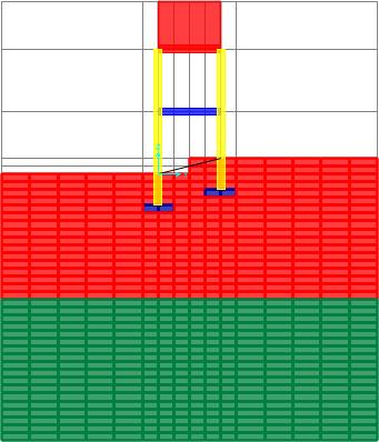
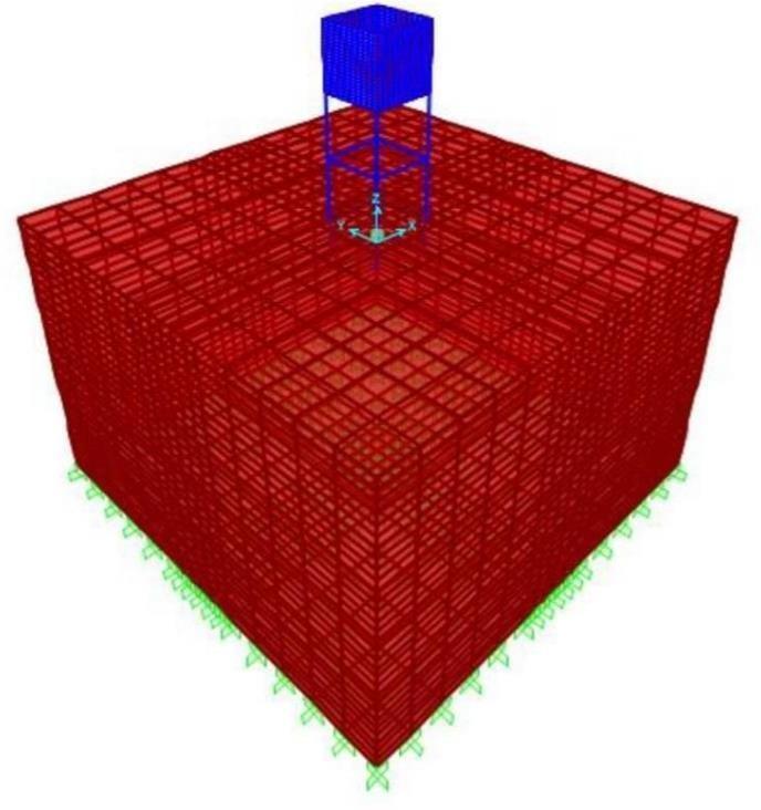
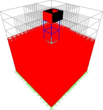
Figure 3: Soil-StructureInteractionmodelofwater tankonslopedgroundforcombination1soilprofile.
Table 6: BaseShearinzoneIIforemptytank condition
1.Increasing ground Sloping leads to higher frequencies and shorter time periods. This signifies a correspondingimprovementinstructuralstiffness.
2.The analysis of empty water tank for combination 1, considering stratified Soil-Structure Interaction (SSI) exhibits a decrease in displacements at different heights 4m, 8m, 11m as the ground sloping increases, indicating potential stability with steeper ground slopes.
3.Base shear values increases with increase in ground sloping suggests stability and effective resistance to seismicforces.
2. Combination 2 – 4m Soft clay + 14m loose sand
Table 7: ModalParametersforemptytankcondition

Table 8: Displacementsforemptytankcondition
Figure 4: Displacementsv/sGroundslopeindegreesfor combination2Soilprofileinemptytankcondition


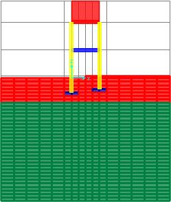
Figure 5: Soil-StructureInteractionmodelofwatertankon slopedgroundforcombination2soilprofile
Table 9: BaseShearforcombination2soilprofileinempty tankcondition
degrees
1.The displacements of the water tank in combination 2, considering 4m clay +14m sand reveals a different pattern. Displacements decreases up to a 100 ground slope, indicating a stiffer response to seismic forces. However at 100 , displacementincreasesasfrequencydecreasesdue to stiffness variation suggesting a shift towards greater flexibility.. However, beyond 100 displacements decreases indicating a stiffer response to seismic forces. Thus indicating the effectofstratification.
2.ThevariationofBaseShearwithdeformationswith increase in sloping ground ranging from 00 to 200 with 50 intervals, underscore the structure's ability to manageseismicforceseffectively.
3.The seismic analysis reveals an increase in frequency and a decrease in time period of the watertankwithhighergroundslopingbeyond100 This signifies a corresponding improvement in structuralstiffness.
Table 10: ModalParametersforemptytankcondition
Table 11: Displacementsforemptytankcondition
Ground slope in Degrees Displacements


Ground sloping in degrees

Figure 6: Displacementsv/sGroundslopeindegrees forcombination3Soilprofileinemptytankcondition
International Research Journal of Engineering and Technology (IRJET) e-ISSN:2395-0056
Volume: 11 Issue: 06 | Jun 2024 www.irjet.net
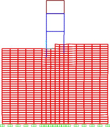
Figure 7: Deformedshapeofwatertankon slopedground
Table 12: BaseShearforcombination3soil profileinemptytankcondition
Ground slope in degrees Base Shear (kN)
1.The variation in displacement and frequency with increase in sloping ground ranging from 00 to 200 with 50 intervals is lighter , indicating stiffer soil profile.
2.ThevariationofBaseShearwithdeformationswith increasein sloping ground ranging from 00 to 200 with50intervals,underscorethestructure'sability tomanageseismicforceseffectively .
4. Combination 4 – 6m loose sand + 6m Soft clay + 6m loose sand
Table 13: ModalParametersforemptytankcondition

Table 14: Displacementsforemptytankcondition.
Ground


Figure 8: Displacementsv/sGroundslopein degreesfor combination4Soilprofileinemptytankcondition
Figure 9: Soil-StructureInteractionmodelofwater tankonslopedgroundfor combination4soilprofile Ground
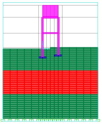
Table 15: BaseShearforcombination4soilprofilein emptytankcondition

1.The displacements of the empty water tank conditions reveals a different pattern. Displacements increases for 50 ground slope suggesting greater soft soil flexibility and larger deformationns.However,beyond50 displacements decreases indicating a stiffer response toseismic forces.
2.Baseshearvalues increase with increasing ground slope beyond 50 Increase in Base Shear suggests stabilityandeffectiveresistancetoseismicforces.
3.The seismic analysis reveals an increase in frequency and a decrease in time period of the water tank with higher ground sloping beyond 50 This signifies a corresponding improvement in structuralstiffness.
Theseismicanalysisofawatertankrestingonleveled and sloped ground considering different soil combination, the analysis focuses on the seismic responseofthewatertankundertheconditionofafull tank, considering both impulsive and convective pressures.
FollowingfactorsareconsideredfromrelevantIScode, forseismicanalysisinzoneII.
Zonefactor:0.10(Table2,IS1893(Part1):2016)
ImportanceFactor:1.5(Table1,IS1893(Part2):2014)
Response Reduction Factor: 4 (Table 2, IS1893 (Part 2):2014)
Table 16: WaterpressuredetailsforzoneII
Table17: ModalParametersforfulltankcondition

Table 18 :Displacement for full tank condition
10: Fulltankconditionofelevatedwater tankonslopedground
International Research Journal of Engineering and Technology (IRJET) e-ISSN:2395-0056
Volume: 11 Issue: 06 | Jun 2024 www.irjet.net
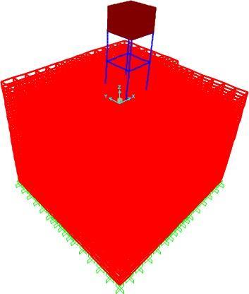
Figure 11: Deformedshapeofelevatedwatertank onslopedground
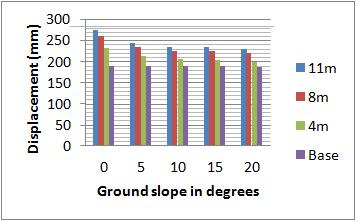
Figure 12: Displacementsv/sGroundslopeindegreesfor combination1Soilprofileinfulltankcondition
Table 19: BaseShearforcombination1soilprofilein fulltankcondition
4.Base shear values increases with increase in ground sloping suggests stability and effective resistancetoseismicforces.
6. Combination 2 – 4m Soft clay + 14m loose sand


1.Displacement is more in full tank condition due to applicationofwaterpressure.
2.Increasing ground Sloping leads to higher frequenciesandshortertimeperiods.Thissignifiesa correspondingimprovementinstructuralstiffness.
3.The analysis of full water tank for combination 1, considering stratified Soil-Structure Interaction (SSI) exhibits a decrease in displacements at differentheights4m,8m,11masthegroundsloping increases, indicating potentialstability with steeper groundslopes.


Figure 13: Displacementsv/sGround slopein degees for combination2Soilprofileinfulltankcondition.
1. The analysis of full water tank for combination 2, considering the effect of stratification exhibits a
International Research Journal of Engineering and Technology (IRJET) e-ISSN:2395-0056
Volume: 11 Issue: 06 | Jun 2024 www.irjet.net
decrease in displacements at different heights 4m, 8m,11masthegroundslopingincreases,indicating potentialstabilitywithsteeperground.
2. Increasing ground Sloping leads to higher frequenciesandshortertimeperiods.Thissignifiesa correspondingimprovementinstructuralstiffness.
7. Combination 3 – 6m Soft clay + 6m loose sand+6m soft clay
Table 22:ModalParametersforfulltankcondition

Table 23: Displacementsforfulltankcondition
Table 24: BaseShearforcombination3soilprofilein
p-ISSN:2395-0072

combination3Soilprofileinfulltankcondition
Figure 14: Displacementsv/sGroundslopeindegrees for
1.The displacements of the water tank in combination 3 in full tank reveal a different pattern. Displacements decreases up to a 150 ground slope, indicating a stiffer response to seismic forces. However at 200, displacement increases as frequency decreases due to stiffness variation suggesting a shift towards greater flexibility. Thus indicating the effect of stratification.
2.The variation of frequency 200 due to stiffness variationenhancestheeffectofstratification.
3.The variation of Base Shear with deformations withincreaseinslopinggroundrangingfrom00to 200 with 50 intervals, underscore thestructure's abilitytomanageseismicforceseffectively.
8. Combination 4 – 6m Loose sand + 6m Soft clay + 6mLoose sand
Table 25: ModalParametersforfulltank condition

International Research Journal of Engineering and Technology (IRJET) e-ISSN:2395-0056
Volume: 11 Issue: 06 | Jun 2024 www.irjet.net p-ISSN:2395-0072
Table 26: Displacementsforfulltankcondition
Table 27: BaseShearforcombination4soilprofileinfull tankcondition


Figure 15: Displacementsv/sGroundslopeindegreesfor combination4Soilprofileinfulltankcondition.
1.The displacements of the empty water tank conditions reveal a different pattern. Displacements increases for 50 ground slope suggesting greater soft soil flexibility and larger deformations. However, beyond 50 displacements decreases indicating a stiffer responseto seismic forces.
2.Base shear values increase with increasing groundslope beyond 50. Increase in Base Shear suggests stability and effective resistance to seismicforces.
Based on the results of detailed analysis of an elevated water tank resting on leveled and sloping ground, the followingconclusionscanbemade,
1.Displacements and base shear are higher in full tank conditionduetopresenceofhydrostaticpressure.This indicatesthatthewatermassexertsadditionalseismic forcesonthestructure.
2.Ina fulltankcondition,theeffectofslopinggroundon displacement is influenced by the additional mass of water.
3.The effect of stratified soil layers alters the frequency ofsoilmassduetowhichthedisplacementvariationof thestructurecanbeobservedinstratifiedsoillayers.
4.Whenever structure is resting on stratified soil deposits,frequencyofsoilmassmustbedeterminedso that if soilmass has lower frequency it will lead to largerdisplacementsinstructuresrestingonthem.
5.The effect of stratification is illustrated when alteration of frequency is observed as the slope angle of ground increases from t0 due to stiffness variationinsoilmass.
6.IncaseofCombination1(9msoftclay+9mloosesand) andCombination2(4msoftclay+14mloosesand)soil profile it can be observed that the displacement for Combination1soilprofileatthetopofthetankishigh because of low frequency when compared to Combination2soilprofile.
7.In case of Combination 3(6m soft clay+6m loose sand+6m soft clay) and Combination 4 (6m loose sand+6m soft clay + 6m loose sand) soil profile it can beobserved that the displacement for Combination 3 soilprofileatthetopofthetankishighbecauseoflow frequency when compared to Combination 4 soil profile.
8.The seismic responses of water tank resting on stratifiedsoildepositsdependsonnaturalfrequencyof soilmassanddisplacementisinverselyproportionalto frequency.
9.Base Shear values increases with sloping ground, suggest increased resistance to seismic forces in flexiblebasecondition.
3.The seismic analysis reveals an increase in frequencyand a decrease in time period of the water tank with higher ground sloping beyond 50.Thissignifiesacorrespondingimprovementin structuralstiffness
1. Analysis and design of substructures limit state design,revisedsecondedition-SwamiSaran(2019)
2. L. T. Stavridis (2002) - Simplified Analysis of Layered Soil-Structure Interaction, Journal of Structural Engineering, Vol.128, No. 2, ASCE, ISSN 0733-9445/2002/2-224
International Research Journal of Engineering and Technology (IRJET) e-ISSN:2395-0056 Volume: 11 Issue: 06 | Jun 2024 www.irjet.net p-ISSN:2395-0072
3. Barnali ghosh and S.P.G. Madabhushi (2004)Dynamic soil structure interaction for layered and inhomogeneousground,Vol.8,PaperNo.440
4. IITK-GSDMA(2007)-Guidelinesforseismicdesign ofliquidstoragetanks,NationalInformationCentre forEarthquakeEngineering,IITKanpur.
5. V.J. Ghadage , prof. A.H.Kumbhar (2016) - Soil structure interaction analysis of elevated water storage tank , Internation journal for scientific researchanddevelopment,Vol.4,Issue-5.
6. IS:3370(Part-I)–1965codeofpracticeforconcrete structures for the storage of liquids. (General requirements).
7. IS 1893 (Part 2): 2014 – Criteria for earthquake resistant design of structures. (Liquid retaining tanks).
8. IS 1893 (Part 1): 2016 – Criteria for earthquake Resistant Design of structures. (General provisions andbuildings).
9. Basavangowda G.M, L Govindaraju(2017)Influence of Stratified Soil on Seismic Response of Pile Supported Building, International Journal of Advance Research, Ideas and Innovations in Technology,Volume3,Issue6.
10. Chaithra M, Krishnamoorthy A, Naurin Nafisa P M (2017) - Analysis of Soil - Structure Interaction on Response Of Tanks Filled With Fluid, International Journal of Civil Engineering and Technology (IJCIET)Volume8,Issue7.
11. MohanM.Vaghjiyani,andPravinL.Hirani(2018)Seismic Analysis of Elevated Water Tank on Different Sloping Angle of Ground with Different Height and Capacity, International Research Journal of Engineering and Technology (IRJET) eISSN:2395-0056Volume:05Issue:10
12. Thorat Yogesh, Kadam Yogesh, Kute Sagar and Kashid Sanchit (2017) - AnalysisofWaterTankon Sloping Ground, International Journal of EngineeringSciences&Management.
13. Ranjith P, Thejaswini R. M, L Govindaraju (2021)Seismic analysis of an elevated water tank considering the sloshing effect, International Research Journal of Engineering and Technology, Vol:08Issue:03
14. JayadeepK.S,ThejaswiniR.M,LGovindaraju(2022) - A Study on The Seismic Response of Elevated Water Tank, International Research Journal of
Engineering and Technology (IRJET) e-ISSN: 23950056Volume:09Issue:03.
15. Deeksha Jain, Deepak Kumar Bandewar, Sachin Jat (2022) - Dynamic Analysisof Intze Tank on Sloped Ground, International Journal for Research in Engineering Application & Management (IJREAM) ISSN:2454-9150Vol-08,Issue-01.
16. Gaurav Sengar, Anil Rajpoot (2022) - Design Analysis andComparison of OverHead Water Tank for Different Wind Speed and Seismic Zones as Per Indian Standard Codes, International Journal of Research Publication and Reviews, Vol3, no 9, pp 1331-1337.
17. Hariram Rimal, Piyush Pradhan, Dipendra Gautam, and Rajesh Rupakhety(2023) - Seismic Fragility of Aging Elevated Water Tank with Smooth Bars Considering Soil Structure Interaction, Buildings 2023,13,4(MDPI)