
International Research Journal of Engineering and Technology (IRJET) e-ISSN: 2395-0056 p-ISSN: 2395-0072
Volume: 11 Issue: 06 | Jun 2024 www.irjet.net
International Research Journal of Engineering and Technology (IRJET) e-ISSN: 2395-0056 p-ISSN: 2395-0072
Volume: 11 Issue: 06 | Jun 2024 www.irjet.net
Nenavath Sunitha1 and Dr. S Tara Kalyani 2
1 M.Tech, Student, Dept. of Electrical and Electronics Engineering, JNTUHUCEST, Hyderabad, India.
2 Professor of Electrical and Electronics Engineering JNTUHUCEST, Hyderabad, India.
Abstract - Most multilevel inverter-fed motor drivesystems largely use pulse width modulation (PWM) techniques, which give a steady switching frequency, favorable total harmonic distortion (THD) characteristics, and lower ripple current. Harmonic loss is evaluated using several PWM strategies, including In-phase sinusoidal pulse width modulation (IPSPWM), phase opposite sinusoidal pulse width modulation (POSPWM) and space vector pulse width modulation (SVPWM). These techniques are then applied to an induction motor drive for comparison. The suggested methods employ a multilevel inverter to achieve better speed control for induction motor drives. The study compares several modulation strategies in terms of harmonic content, speed, and torque characteristics of the drive system. The major goal is to investigate the effects of various modulation approaches on the performance of a multilevel inverter-fed drive system and which is the best among them. The proposed techniques are implemented in the MATLAB/SIMULINK environment.
Key Words: PWM, Induction motor drive, Neutral Point Clamped (NPC) inverter, In-phase sinusoidal PWM, phase opposite sinusoidal PWM and space vector PWM.
Multilevelinverters(MLIs)havegaineda lotofinterestin recent years for their use in high-power and high-voltage applications because of their ability to generate higher voltage levels with less harmonic distortion and electromagnetic interference. They are becoming increasingly used in industrial applications, renewable energy systems, and electric drives. When used to drive induction motors, MLIs offer various advantages over standard inverters, including enhanced output voltage quality, increased efficiency, and lower motor stress. Induction motors are frequently utilized in industrial applicationsbecauseoftheirreliability,robustness,andlow controlneeds.However,whenpoweredbytypicaltwo-level inverters,thesemotorsfrequentlyexhibitsubstantialtotal harmonicdistortion(THD)andsignificantpowerlosses.The
useofMLIscanaddresstheseconcerns,makingthesystem moreefficientandreliable.Theprimarygoalofthisstudyis to enhance the performance of induction motor drives by comparing various modulation schemes for multilevel inverters.Understandingthebenefitsanddrawbacksofeach strategy allows us to discover the best way for certain applications. By addressing restrictions in solid-state switchingdeviceratings,multilevelPWMinvertersenable higher-poweradjustable-frequencydrivestoregulatebigger motors.
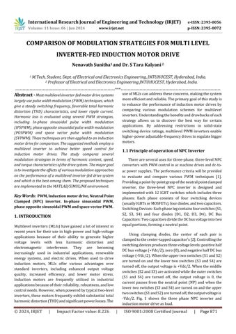
Thereareseveralusesforthree-phase,three-levelNPC converterswithPWMcontrolinacmachinedrivesanddc-toacpowersupplies. Theperformancecriteriawillbeprovided to evaluate and compare various PWM techniques [1]. Providingapoint-by-pointgraspoftheneutralpointclamped inverter, the three-level NPC inverter is designed and implemented with 12 IGBT switches which includes three phases: Each phase consists of four switching devices (usuallyIGBTsorMOSFETs),fourdiodes,andtwocapacitors. SwitchingDevices:Eachphaselegcontainsfourswitches(S1, S2, S3, S4) and four diodes (D1, D2, D3, D4). DC Bus Capacitors:TwocapacitorsdividetheDCbusvoltageintotwo equalportions,forminganeutralpoint.
Using clamping diodes, the center of each pair is clampedtothecenter-tappedcapacitor's[2].Controllingthe switchingdevicesproducesthreevoltagelevels:positivehalf DCbusvoltage(+Vdc/2),zero(0),andnegativehalfDCbus voltage(-Vdc/2).Whentheuppertwoswitches(S1andS2) areturnedonandthelowertwoswitches (S3andS4)are turnedoff,theoutputvoltageis+Vdc/2.Whenthemiddle switches(S2andS3)areactivatedwhiletheouterswitches (S1 and S4) are turned off, the output voltage is 0, the current passes from the neutral point (NP) and when the lowertwoswitches(S3andS4)areturnedonandtheupper twoswitches(S1andS2)areturnedoff,theoutputvoltageis -Vdc/2. Fig. 1 shows the three phase NPC inverter and inductionmotordriveasload.
Volume: 11 Issue: 06 | Jun 2024 www.irjet.net
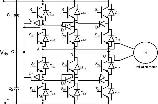
When a triangular carrier wave and an input reference waveform intersect, naturally sampled PWM generates switchinginstants.Thecarrierwaveautomaticallysamples the input waveform, and the sampling instant occurs simultaneously with the output edge. SPWM involves multiplyingtheinputsignal'sfundamentalfrequencybythe carrierorswitchfrequency,istypicallyusedwithalowpulse number( ).InnaturalSPWM,spectrumincludesthe input signal , carrier , harmonics To avoid numerous switchingedgeseachswitchcycle;Theslewrateoftheinput signalisreduced.Theinputsignal'sslopeshouldnotsurpass the triangle carrier wave's slope, while staying within the boundary.

ThebandsarecontinuousforanN-levelinverterwhen N-1carrierswiththesamefrequency( )andpeak-to-peak amplitude ( )areorganized.Positionedatthecenterofthe carrierset,thereferenceormodulationwaveformhaspeakto-peak amplitude and frequency .Everycarriersignal and the reference are continually compared. The carrierassociatedactivedeviceisturnedonifthereferencesignalis greaterthanthecarriersignal.Thecarrier-associatedactive deviceisturnedoffifthereferenceislessthanthecarrier signal.Thisapproachcomparestwocarriersignals( and )withonereferencesignal( ).Thecarriersignalmaybe IPSPWMorPOSPWM.Theswitchinglogiciscomputedinthe followingwaysforbothmethods.Inthepositivehalfcycleof the fundamental, this type of SPWM alternates between states+1and0,andinthenegativehalfcycle,italternates betweenstates-1and0.Apairofcarriersforathree-level inverterthatareallinphaseandinoppositiontoeachother.
2395-0072
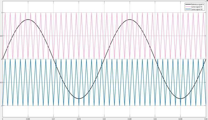
Table -1: CircuitparametersofNPCinverterand inductionmotorrating
C2)
Designing a second order low pass filter for an inverter's three-phase output voltage using the cutoff frequencyanddampingfactorentailsdevelopingafilterthat not only attenuates high-frequency components but also providesthedesiredtransientresponse.

Volume: 11 Issue: 06 | Jun 2024 www.irjet.net
International Research Journal of Engineering and Technology (IRJET) e-ISSN: 2395-0056 p-ISSN: 2395-0072

TheSimulationresultsillustratetheSPWMapproachfor theNPCinverterfedinductionmotordrive.Thereference signal'samplitudeis0.85,whilethecarriersignal'sis1,for boththetechniquesIPSPWMandPOSPWM.
3(b)
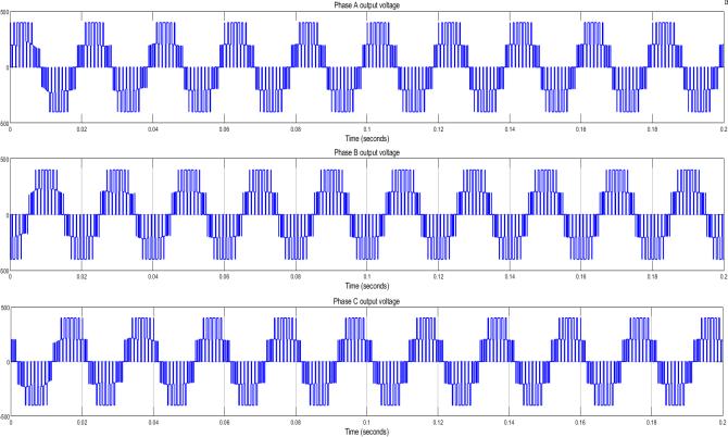
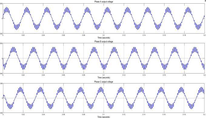
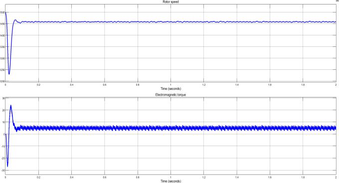
Fig.3(e)
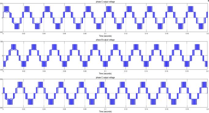
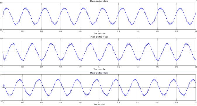
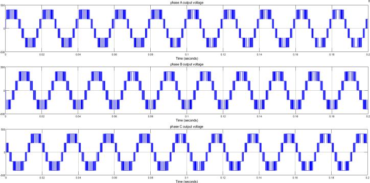
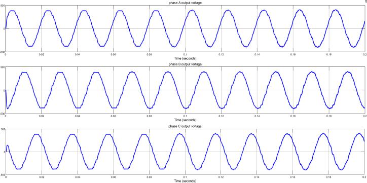
Fig -3: Figures3(a)and3(b)showstheline-to-lineoutput voltageoftheIPSPWMbeforeandafterfilters,respectively. Figure 3(c) and 3(d) are line-to-line output voltage of the POSPWM before and after filters, and Figure 3(e) represents thetorqueandspeedcharacteristicsoftheinductionmotor drive.
Since the inverter's output voltage in this case is not sinusoidal fromthe abovesimulationresult3(a),3(c)and hasahigherorderharmonicdominating,thetotaltransient harmonicdistortion(THD)isreducedbyemployingalow passfilter.Figures3(b)and3(d)confirmsthatthevoltage waveformhasbeenenhancedandappearsalmostsinusoidal after adding filter. At first, the rotor speed exceeds the desiredspeed,thenrotorspeedrapidlystabilizesafter the initial overshoot and stays mostly stable around a predeterminedvalueshowninfig.3(e),indicatingasteady working condition. At first, the electromagnetic torque fluctuates significantly as the system stabilizes, these variations gradually diminish and reveal damped oscillations.Thetorqueisstilloscillatingslightlyonaregular basis.
FFT(FastFourierTransform)analysisisusedtoinvestigate the frequency components of signals, and it is especially valuable in determining the harmonic content of inverter
Volume: 11 Issue: 06 | Jun 2024 www.irjet.net
International Research Journal of Engineering and Technology (IRJET) e-ISSN: 2395-0056 p-ISSN: 2395-0072
output voltages. For a three-phase, three-level inverter, FFT analysismayhelpindeterminingthequalityoftheoutput waveform as well as the existence and magnitude of harmonics. To transform the time-domain voltage waveformstothefrequencydomain,applyanFFTtechnique. This will offer amplitude and phase information for the frequency components in the waveform. Identify and evaluate the harmonics in the frequency domain representation. Total Harmonic Distortion (THD) is an importantstatisticinpowerelectronics,notablyininverters.
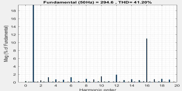
Fig.4(a)
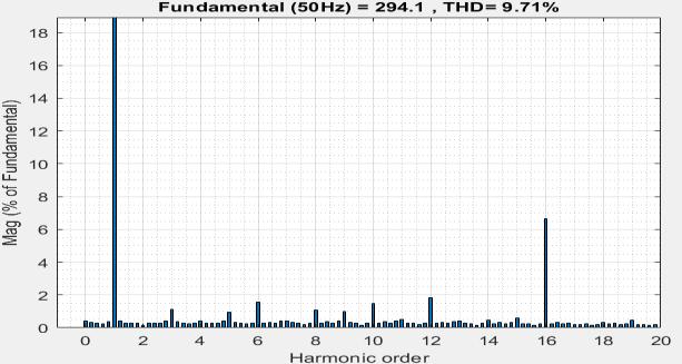
Fig.4(b)
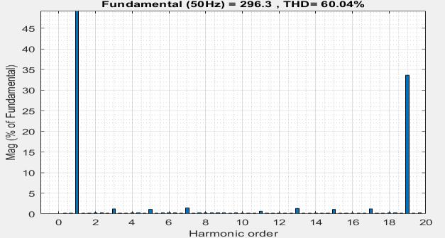
Fig.4(c)
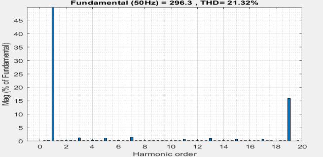
Fig.4(d)
Fig -4: FFT analysis of IPSPWM strategy for NPC inverter shownin4(a)and4(b)beforeandafterfilter,4(c)and4(d) areFFTforthePOSPWMbeforeandafterfilter.
The fundamental frequency (50 Hz) is the largest component,measuring294.6.The16thharmonic(about800 Hz)isthesecondmostsignificantcomponent,accountingfor around11%ofthefundamental.Otherharmonicsexistbut haveconsiderablylessermagnitudes,addingtotheoverall THDshowninfig.4(a).after addingfilterthe 16thharmonic isstillpresent,butitsquantityhasbeenreducedtoaround 6% of the fundamental shows in fig. 4(b). The overall harmoniccontentissignificantlyreduced,demonstratingthe filter's effectiveness in minimizing harmonic distortion. Overall, the filter significantly improved the waveform, loweringtheTHDfrom41.20%to9.71%forIPSPWM.
The fundamental frequency was the most significant component, at 293.6. The 19th harmonic (950 Hz) is the second most prominent component, accounting for approximately 34% of the fundamental. Other harmonics exist,buttheirmagnitudesarefarlower,contributingtothe overallTHDshowninfig.4(c).afteremployingafilterthe 19th harmonic is still there, but its quantity has been reducedtoaround16%ofthefundamental,asshowninfig. 4(d).Theoverallharmoniccontenthasbeengreatlyreduced. The filter enhanced the waveform by reducing THD from 60.04%to21.32%forPOSPWM.
TheSVMapproachgeneratesthreephasevoltageswitheach state switching at a specific time interval. A vector output changesasaresultofavoltagevectorshiftingfromsector onetotheneighboringsector.Theswitchingstatetimeand patternsmustalwaysbeunderstoodintermsofareference voltagevector.Thethreevoltagesinphasesare:
International Research Journal of Engineering and Technology (IRJET) e-ISSN: 2395-0056 p-ISSN: 2395-0072
Volume: 11 Issue: 06 | Jun 2024 www.irjet.net
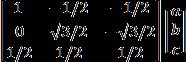
The abc → αβ (alpha-beta) transformation, or Clarke transformation,turnsthree-phasevariablesintotwo-phase orthogonalcomponents.Thistransformationmakesiteasier to analyze and operate three-phase systems by projecting them onto a two-dimensional plane. The Clarke transformationmatrixconvertsthree-phase(abc)quantities totwo-phase(αβ)quantitiesasfollows:a,b,andcrepresent thethree-phasequantities.αandβrepresentthetwo-phase orthogonalcomponents.

=2/3
TheParktransformationconvertstheαβcomponents to a rotating reference frame (d-q frame). This transformation is useful for evaluating and managing alternatingcurrentmachinesandpowerconvertersbecause italignsthereferenceframewiththerotatingmagneticfield, simplifyingequations.Theangleθindicatesthepositionof therevolvingreferenceframeinrelationtoafixedreference. Itcanbecalculatedbyintegratingtheangularvelocity(ω) across time. The transformation matrix for transforming αβ components to d-q components is as follows: α and β representthestationaryreferenceframecomponents.dand qrepresenttherotatingreferenceframecomponents.


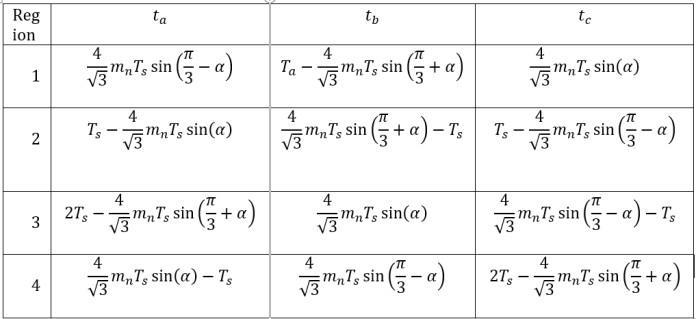
Three-phase inverters can be controlled with the advanced modulation method known as space vector modulation(SVM).SVMcanbeexpandedtohandletheextra voltage levels for a three-level inverter, providing improved harmonicperformanceandmoreeffectiveuseoftheDCbus voltage.Threelevelsandthreephasesmakeupathree-level converterwith27switchingstates,suchasPPP,OOO,and NNN. Twelve short, six medium, six long, and three null vectorsmakeupthe24activevectors.Therearesixsectors created, with four regions (1-4) in each, for a total of 24 regions.
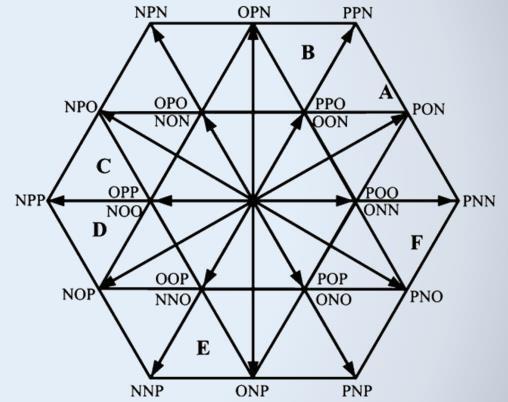
Divide the αβ plane into six primary sectors (each 60 degrees)anddeterminewherethereferencevectorfalls.A three-level inverter's sectors are further divided into four areas.Choosethethreeclosestvectorsthatformatriangle around the reference vector. These vectors are chosen according to the sector and the area that contains the referencevector.Calculatethetime period for each of the three vectors to be applied inside one PWM cycle to synthesizethereferencevector.Thisisaccomplishedwith thefollowingequations:
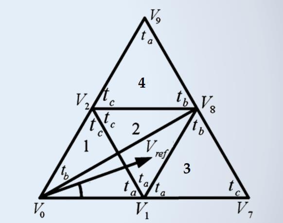
-6:Regiondivisioninasector
Assumingthe remainsinregion-2,voltagevectorsV1, V2,andV8canbeusedtoaccumulateit.TheequationofON timeofthevoltagevectorscanbegivenas:
Modulationindex( )

Volume: 11 Issue: 06 | Jun 2024 www.irjet.net
International Research Journal of Engineering and Technology (IRJET) e-ISSN: 2395-0056 p-ISSN: 2395-0072
Region selection is depend on the modulation index ( ).Thismodulationindexisdividedintotwoparts and toknowthe islyinginwhichregion.Conditionsare appliedfortheregionselection.
Ifthevalueof , and( )<0.5,then liesin region-1
Ifthevalueof and <0.5and( )>0.5,then liesinregion-2
Ifthevalueof >0.5,then liesinregion-3
Ifthevalueof >0.5,then liesinregion-4


Table -2: OntimeofthevoltagevectorsorSwitchingtime forsectorA
3.1 Simulation results
Whenitcomestovoltageutility,spacevectorPWMfor three-level converters has a benefit over sinusoidal PWM sinceitsmodulationrangeis15%greater.Thestepsareas follows:first,determinethereferencevector;next,choose the sector; last, choose a specific area within which the referencevectorislocated.determiningthetimingofeachof the three vector forming triangle and distributing the relevantPWMswitchesontime.

Volume: 11 Issue: 06 | Jun 2024 www.irjet.net
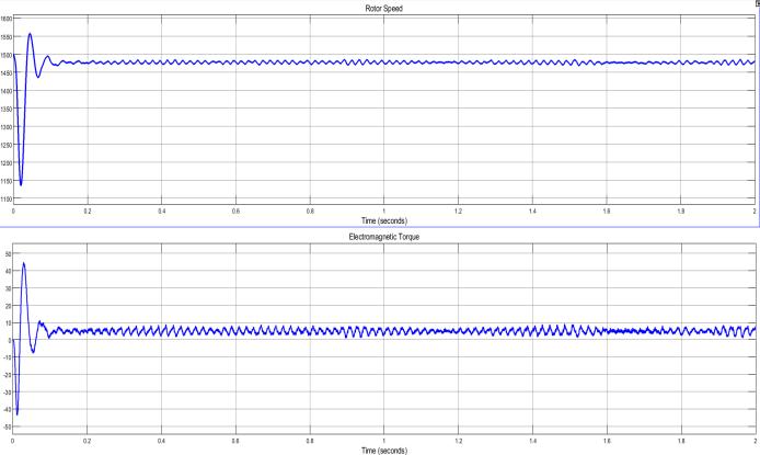
Fig.7(e)
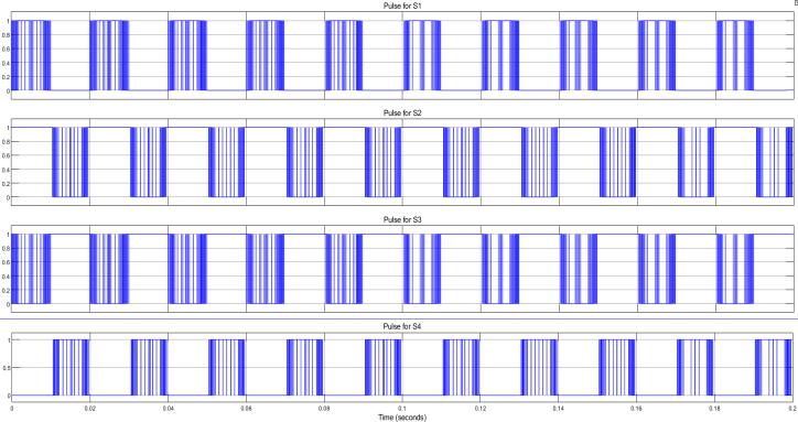
Fig -7: Figure 7(a) demonstrated the output voltage and currentofthethree-level,three-phaseinverter.Figure7(b) indicatestheswitchingpulsefortheinverterswitches,and theRMSline-to-linevoltageforthethreephasesbeforeand after the filter is shown in 7(c) and 7(d). 7(e) depicts the drivesystem'scharacteristics.
Initially, there is a transitory response. After the transient period, the currents settle into sinusoidal waveforms, indicating steady-state performance in a balancedthree-phasesystemthisisconfirmedfromfig.7(a). Fromfig.7(b)thetopmostfiguredisplaysthePWMsignal for one of the inverter's switches (S1). The second panel shows the PWM signal for another switch (S2) in the inverter.Theswitchingpatternhereisphase-shiftedwhen compared to S1, which is required to generate the proper phase relationship in the output voltages and so on. The graphs7(c)illustratestaircase-likewaveformscausedbythe inverterswitchingbetweenvoltagelevels.Afterapplyinga filter to the output voltage, when compared to the SPWM method, it was shown to be pure sinusoidal. It was found that the speed-torque characteristics of SVPWM bettered thanSPWMintermsofperformance.
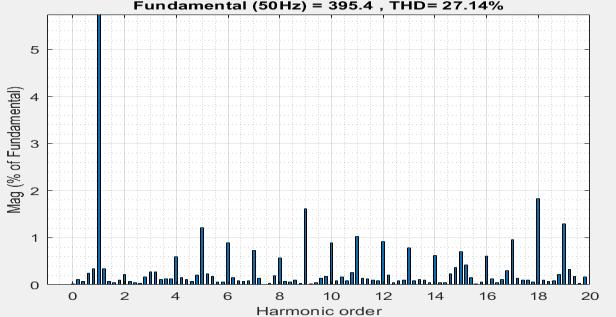
Fig.8(a)
p-ISSN: 2395-0072
8(a)
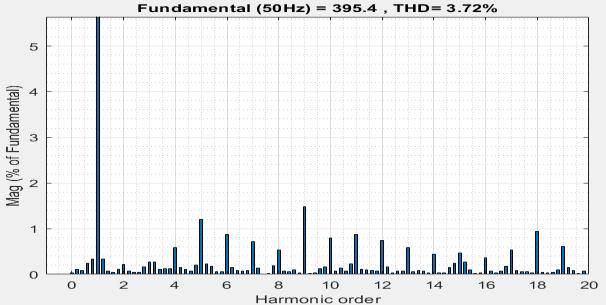
-8: 8(a) and 8(b) shows the FFT for the SVPWM techniquebeforeandafterfilter.
Thereisa50Hzfundamentalfrequency.Themagnitude ofthefundamentalcomponenthasbeenadjustedto395.4%. The THD is 27.14%, suggesting a high level of harmonic distortionrelativetothefundamentalcomponent.Thereare detectable harmonics in the 2nd, 3rd, 5th, 7th, 9th, 11th, 13th,15th,and17thorders.Someoftheseharmonicshave larger magnitudes, which add tothe overallTHD, this can be seen in fig, 8(a). The magnitude of the fundamental component remains at 395.4%. Adding a filter to the NPC inverter-fedinductionmotordrivedrasticallyloweredTotal Harmonic Distortion from 27.14% to 3.72%. Previously strongharmonicsatorderssuchasthesecond,third,fifth, and others have muchsmaller magnitudes. The addition of a filtersignificantlyreducedthemagnitudesofbothlowerand higherorderharmonicswhichcanbeconfirmedfromthefig. 8(b).
Table -3: Comparisonof%THDofinverterline-to-line outputvoltagewithIM
SI.NO Various modulation Strategy BeforeFilter AfterFilter
ThemotorspeedcontrolusingSPWMwassteadybut exhibited small variations due to the increased harmonic content, whereas SVPWM resulted in smoother and more stablespeedcontrol,withlessharmonicdistortion.Torque producedbySPWMshowedsomeripple,whichwascredited bythegreaterharmoniccontent.Thetorqueperformance with SVPWM was superior, with less ripple and smoother torquecharacteristicsduetodecreasedharmoniccontent.
International Research
Volume: 11 Issue: 06 | Jun 2024 www.irjet.net
of Engineering and Technology (IRJET) e-ISSN: 2395-0056 p-ISSN: 2395-0072
Comparison of modulation strategies for multilevel inverter fed induction motor drive was carried out to determine the performance of three control strategies for threelevelNPCinverter.ThestudyaimedtoachieveTHDof theinverteroutputvoltageandspeed-torquecharacteristics of the drive system for the three strategies. The findings showedthatSVPWMcontroltechniqueoffersmoreaccurate switchingthantheothertwostrategies,althoughIPSPWM, POSPWM, and SVPWM are all suitable for controlling the switchingoftheinverterdevicestoprovidethenecessary output voltage waveform. Improved speed-torque characteristicsandlessharmonicdistortionaretwoother reasonswhySVPWMisabetterchoiceforhigh-performance applications. In broadly, this research focuses light on the possible advantages of three distinct strategies for NPC inverter-fed induction motor drives that operate in three phasesandthreelevels.
1. R. K. Behera, T. V. Dixit and S. P. Das, "Analysis of Experimental Investigation of Various CarrierbasedModulationSchemesforThreeLevelNeutral Point Clamped Inverter-fed Induction Motor Drive," 2006 International Conference on Power Electronic,DrivesandEnergySystems,2006,pp.16,doi:10.1109/PEDES.2006.344417.
2. K. Reddy Sudharshana, V. Muralidhara, A. RamachandranandR.Srinivasan,"AnalysisofTotal Harmonic Distortion in 5-level Inverter fed InductionMotor,"2018InternationalConference on Computing, Power and Communication Technologies (GUCON), Greater Noida, India, 2018, pp.800-804,doi:10.1109/GUCON.2018.8674891.
3. A.Nabae,I.Takahashi,andH.Akagi,"Anewneutralpoint-clamped PWM inverter," IEEE Trans. Ind. App.,vol.IA-17,pp.518-523,Sept./Oct.1981.
4. D. G. Holmes, "A general analytical method for determiningthetheoriticalharmoniccomponentof carrierbasedPWMstrategies,"inConf:Rec.IEEEIASAnnu.Meeting,1998,pp.1207-1214.
5. J. Holtz, " Pulsewidth Modulation for Electronic Powerconversion,"ProceedingsoftheIEEE,Vol. 82,No.8,Aug.1994,pp.1194-1214.
6. H. S. Black, Modulation Theory, D. Van Nostrand Company,Inc,Princeton,1960.
7. B. Velaerts, P. Mathys and E. Tatakis, "A Novel Approach to the Generation and Optimizationof three level PWM waveforms," in Proc. IEEE PESC'88.Conf.,1988,pp.1255-1262.
8. D.G.HolmesandT.A.Lipo,"PulseWidthModulation For Power Converters Principles and Practice, IEEE press series on Power Engineering, IEEE Press, Wiley-Interscience,Piscataway,2002.
9. G.K.DubeyandCR.Kasarabada,PowerElectronics and Drives,IETE Book Series. Vol. I.Tata-Mc Graw Hill,1993.
10. Y. Liu, X. Wu, and L. Huang, "Implementation of three-level inverter using a novel space vector modulation algorithm," in IEEE Conference Proc. on Power System Technology, vol. 1, pp.606-610, Oct.2002.
11. B. Muralidhara, “An Experimental Evaluation of Two level and multilevel inverter used for speed control of Induction Motor and study of Common ModeVoltageinbothcases”.
12. G. Narayanan, and V.T. Ranganathan, “Synchronised PWM strategies based on space vector approach : Principles of waveform generation”, IEEE Proceedings- Electric Power Applications, vol 146 No.3,May1999,pp.267-275.
13. Nashiren F. Mailah,Senan M. Bashi, Ishak Aris, Norman Mariun “Neutral-Point-Clamped Multilevel Inverter Using Space Vector Modulation” European Journal of Scientific Research, Vol.28 No.1 (2009), pp.82-91.
14. Reddy Sudharshana K, A Ramachandran, V Muralidhara and R Srinivasan, “Simulation with Experimental Measurement of Voltage Total Harmonic Distortion and Harmonic Frequency in Three-Phase InductionMotorfedfromInverter”,in WCEproceedings,July2017,pp.317-322
15. P. Hothongkham and V. Kinnares, "Investigation into Harmonic Losses in a PWM Multilevel cascaded H-Bridge Inverter Fed Induction Motor," 2007 7th International Conference on Power Electronics and Drive Systems, 2007, pp. 10431048,doi:10.1109/PEDS.2007.4487832.