
International Research Journal of Engineering and Technology (IRJET) e-ISSN: 2395-0056
Volume: 11 Issue: 06 | Jun 2024 www.irjet.net p-ISSN: 2395-0072
International Research Journal of Engineering and Technology (IRJET) e-ISSN: 2395-0056
Volume: 11 Issue: 06 | Jun 2024 www.irjet.net p-ISSN: 2395-0072
Madhuri Thombre1 , Rajeev Arora1 , Prasanth Karakavalasa1
1Cummins Technologies India Private Limited, Cummins India Office Campus, Balewadi, Pune-411045, Maharashtra, India.
***
Abstract - The fuel-injector nozzle is a vital component in diesel engine, profoundly influencing engine performance. Enduring extreme conditions like high temperatures and pressures up to 3,000 bar during operation, it demands high strength, wear resistance, and fatigue strength, achievable through careful material selectionandpreciseheattreatment. Despite extensive research on gas nitriding process parameters and their impact on nitriding properties across steel grades, understanding the effects of surface structure, composition, and contaminants on the process remains challenging. In the current study, an attempt was made to understand effect of surface contaminants on effective case depth of injector nozzle subjected to zero-flow gas nitriding process which offers precise process control compared to the double component gas nitriding process. While zero-flow technology has been successfully demonstrated in car applications for diesel enginefuelinjectornozzles,itsadoption in high-end diesel engine applicationsliketrucksandtippersis still limited. In this study, high-end injector nozzles made of H13 steel was subjected to zero-flow gas nitriding at 500±50℃ for varying time intervals. Nozzles with RP oil stains, cutting oil stains, and clean surfaces were subjected to gas nitriding to assess the impact of surface contaminants on nitriding properties. Nitriding properties were assessed using optical microscopy and a microhardness tester. The results show that longer nitridingtimesincreaseseffectivecasedepth, but surface contaminants reduces it by impeding nitrogen diffusion, resulting in non-uniformity.Optimizingthesefactors significantly enhances nozzle performance, underscoring the importance of thorough surface preparation in gas nitriding processes.
Key Words: Kn, Effective Case Depth, Surface Hardness, Surface Contaminants, Nitrogen Diffusion.
Abbreviations:
CRDI CommonRailDieselInjector
EDS ElectronDispersiveSpectrum
Kn NitridingPotential
RP RustPreventive
SEM ScanningElectronMicroscopy
ECD EffectiveCaseDepth
DOE DesignofExperiment
GN GasNitriding
VHT VacuumHardening&Tempering
The common rail diesel injection (CRDI) fuel injection system stands as a critical component in diesel engines employedinon-highwayapplicationsliketrucksandtippers. Itsprimaryfunctionistoinjectfuelintotheenginecylinders throughasingular,sharedlineknownasthecommonrail. Thiscommon rail isinterconnectedwithall fuel injectors. Operatingasanaccumulator,thecommonrailplaysapivotal roleinensuringaconstantfuelpressuredeliverytothefuel injectors up to 3000 bar [1][3] . A fuel injector is an electronicallycontrolledvalvesuppliedwithpressurizedfuel bythefuelpump,thatsprayspressurizedfuelasafinemist for efficient combustion in an engine [2][3] Hence injector nozzle is a vital component of diesel engine for the performanceandemissionsofmoderndieselengines With key design parameters such as the injector seat, sac, and nozzle hole size and shape significantly influencing combustioncharacteristics,emissionsstability,performance consistency,andinjectordurabilityovertime[2][3]
The fuel injector nozzle operates under extreme conditions,enduringhighpressureandtemperaturesduring the combustion process in an internal combustion engine which makes them susceptible to accelerated wear and defects.Therefore,thedesignoffuel-injectionnozzlesmust prioritize adequate strength, impact resistance, fatigue resistance, and abrasion resistance [6]. For high end application such as trucks and tippers wherein injection pressuresarebeyond2000bar,Gasnitridinghasemergedas an optimal heat treatment process capable of imparting theseessentialpropertiestothenozzle,ensuringdurability andperformanceunderextremeconditions.Itinvolvesthe formation of a robust nitride layer on the surface of the nozzlewhichsignificantlyenhancesthesurfaceresistanceto wearanderosion[4]. Itimpartsgooddimensionalstabilityto the component and is considered a low-temperature process,typicallyconductedat~500°C±50℃.Furthermore, thesurfacehardnessachievedthroughgasnitridingimparts sufficientfatiguestrengthtothenozzle.Theformationofa whitelayerduringtheprocessenhancesthewearresistance and corrosion resistance of the nozzle and serves as an additional protective barrier against the challenging conditionsencounteredduringengineoperation.
Inthepresentwork,zeroflownitridingtechnology wasusedtonitridehotworkingtoolsteelH13fuelinjector
International Research Journal of Engineering and Technology (IRJET) e-ISSN: 2395-0056
Volume: 11 Issue: 06 | Jun 2024 www.irjet.net p-ISSN: 2395-0072
nozzlesusedintruckandtipperapplications.Anovelcasehardeningtechnologysuchasvacuumcarburizing&vacuum nitriding was introduced by seco in 2014, marking a significant advancement in the heat treatment of diesel enginefuel-injectionnozzlescraftedfromhot-workingtool steel,havebeenemployedtoenhancesurfacepropertiesof nozzle, particularly beneficial for complex geometries of nozzlessuchasblindholes(1mmdeephole-seat/sacarea), as seen in injector nozzles [6][7] With rigorous testing the technology was deemed ready for industrial deployment, signifying a milestone in enhancing the durability and performance of fuel-injection nozzles in diesel engines [6] . Building upon their earlier innovations, Seco further advancedthefieldbyintroducingthezeroflowconcept a gas nitriding process that is not only economical but also environmentally friendly. This breakthrough enables a significantreductionintheconsumptionofindustrialgases comparedtoexistingprocesses,representingamajorstride towardssustainabilityinheattreatmentpracticesfordiesel engine fuel-injection nozzles and other components, enabling the formation of layer phase structures with comparable precision to processes utilizing doublecomponentatmospheres [10][11].Thistechnologyisfoundto have been successfully implemented for car engine parts such as crankshafts, camshafts, piston rings, poppet valve springs and discs, piston pins, or nozzles [8][9]. It became popularbecauseitutilizesasingle-componentatmosphere, specifically raw ammonia (NH3), for the nitriding process, and control of the nitriding potential Kn is achieved by adjusting the chemical composition of the nitriding atmosphere,whichissolelymanagedbytemporarilyhalting and then reactivating the feeding of NH3 into the furnace [10][11] Somestudieshaveshownthatdieselengine nozzles used in trucks and tipper applications can alsobe vacuumnitridedwiththeuseofamixtureofgasessuchas NH, CO2 & N2 for the nitriding process [7]. While zero flow technology has been demonstrated for diesel engine fuel injectornozzlesin-carapplication,itsadoptioninhigh-end dieselengineapplicationssuchastrucksandtippersremain limited. The current study attempted to apply zero flow nitriding technology to diesel engine fuel injector nozzles usedintruckandtipperapplications,wherehighinjection pressuresupto2000bararecommon.Whiledoingthis,our focusisoncomprehendingtheimpactofnitridingprocess parametersandsurfacecontaminantsontheeffectivecase depthtounveilthecorrelationbetweentheseparametersfor theH13injectornozzle
2.1. Material
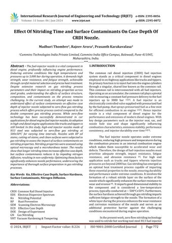
In the current work, ingot casted, hot rolled & spherodized annealed H13 steel was studied as an experimentalmaterial.Table1showsthestandardchemical compositionofthesteel.ThemicrostructureofH13steelis composedofaferritematrix,withauniformdistributionof
spherodizedcarbides,showninFigure1.Thesecarbidesare composedofmolybdenum,vanadium,chromium,andiron.
Table – 1: ChemicalCompositionofH13Steel(mass%)
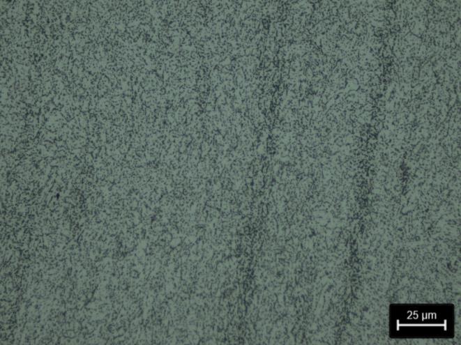
Fig-1:MicrostructureofIngotCasted,HotRolled& SpherodizedAnnealedH13Steelat500XMagnification
The processing of the nozzle right from the raw materialstagetofinishmachiningisexplainedinapictorial viewasshowninfigure2.
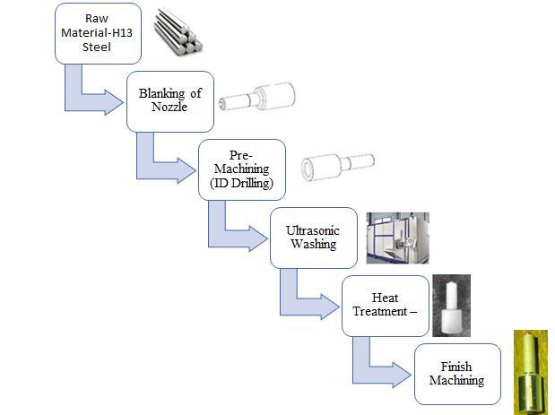
Fig-2: ManufacturingRouteofInjectorNozzle.
2.2.1 Heat Treatment Process
Pre-machined(blanking+iddrilling)nozzleswere RPoiledtoprotectthemfromrustgeneration Beforeheat
International Research Journal of Engineering and Technology (IRJET) e-ISSN: 2395-0056
Volume: 11 Issue: 06 | Jun 2024 www.irjet.net p-ISSN: 2395-0072
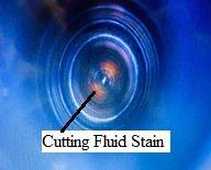
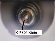
treatment,ultrasonicwashingofnozzleswascarriedoutto removeRPoilfromparts.Duringultrasonicwashing,itwas observedthatsomepartswashedwitha15-minutewashing cycleleftsometracesofRPoilstainsina1mmdeepholeof thenozzlewhichistheseat/sacareaasshowninfigure5(c). Theotherareasofthenozzlesuchasoutersurface&idwere foundgettingcleanedwithnotracesofanyRPoilstain.
Post washing, parts were loaded into heat treatment fixturesforvacuumhardening&temperingfollowedbygas nitriding. The heat treatment process was designed to achieveeffectivecasedepthcontrolledwithinafewhundred micronswhiletargetingsurfacehardnessgreaterthan800 HKandcorehardnessaslowas462HK.Toimpartsufficient hardnesstothenozzle,vacuumhardeningwascarriedoutat atemperatureof1030±50℃for16±2hrsandgasquenched at15±5barpressuretoproducemartensiticstructure.To eliminate stresses generated during gas quenching & improvetoughness,temperingwascarriedoutat530±50℃ for 4±4 hrs. Once the nozzles were vacuum hardened & tempered,gasnitridingwascarriedwithcontrollednitriding potential at a constant temperature of ~500℃±50℃, for time18-43hrs.
Thewiderangeoftimewaschosentounderstandthe effect of nitriding time on the effective case depth of the nozzle. To ensure precision about compound layer and diffusionzonethickness,itisimportanttohavegoodfurnace temperatureuniformity,typically±5℃ (±41°f)whichwas ensured in gas nitriding furnace. For both processes i.e. hardening/tempering&nitriding,asecofurnacedeveloped bymanufacturerseco(sweden)wasemployed.
ThegasnitridingcycleisshowninFigure3(a),The processstepsinthenitridingcyclehavethreemajorsteps:
1)Heatingtotemperature500℃±50℃
2)Holdingattemperatureforasufficienttimetoreachthe requirednitridingdepthand
3)CoolingwithInertN2 Gas.
DuringVHT&GN,formetallurgicalinspection,nozzles wereloadedat9-locationofthefurnaceasshowninFigure3 (b).Thisistocapturetheoverallfurnaceatmosphereandits effectonmetallurgicalparameters
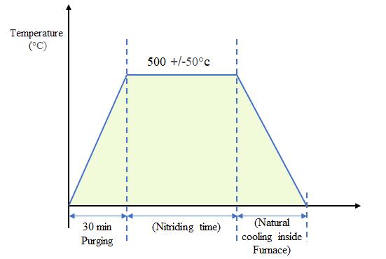
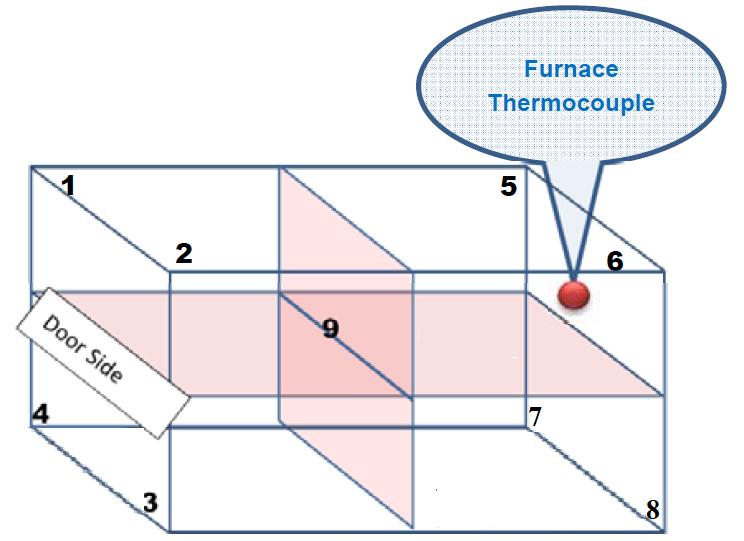
:(a)GasNitridingCycleofInjectorNozzle(b) LoadingofInjectorNozzleinHeatTreatmentFurnaceat9Poles.
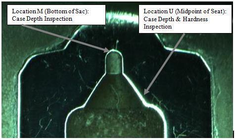
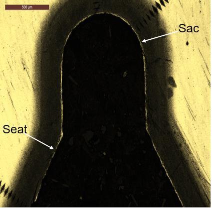
Samplepreparationformetallographicinspection was carried out by cross-sectioning 9-pole nozzles in the centrelinetochecksurfacehardness,effectivecasedepth& corehardnessatthesac(locationM)&seat(locationU)area which are the most critical areas in the nozzle from fuel injectionperspectiveasshowninfigure4.
International Research Journal of Engineering and Technology (IRJET) e-ISSN: 2395-0056
Volume: 11 Issue: 06 | Jun 2024 www.irjet.net p-ISSN: 2395-0072
For optical microscopy, the cross-sections were investigatedusingcarlzeissimagingopticalmicroscope.The samples were mounted, polished with colloidal silica, and etchedwithnital(2-3vol.%HNO3inethylalcohol)forabout 10 secs before the examination. Hardness & case depth measurementswerecarriedoutforheat-treatedsampleson theknoophardnesstesterbyapplyingHK0.5(500g)load. Surface hardness was measured at a depth of 0.05 mm & corehardnesswasmeasuredatadepthof1mm.
The design of the experiments were conducted considering two factors that would impact effective case depthinthegasnitridingprocess.Thesetwofactorswere chosen as nitriding time & surface contaminants. To understand the impact of nitriding time, nozzles were nitrided at different nitriding times (18-43 hrs) keeping temperature&knasconstant.Tounderstandtheimpactof surface contaminants, different sets of samples were prepared and subjected to a heat treatment process. The combinationofsampleswasasfollows:
1) NozzledippedinRPOil(withnowash)
2) Nozzlewithcuttingoilstaininseat/sac area (withno wash),
3) Nozzle with contamination in seat/sac area (contaminationcouldbecuttingoilstainorrpoilstain postwashing)
4) Nozzlewithnocontamination(withpostwash)
International Research Journal of Engineering and Technology (IRJET) e-ISSN: 2395-0056
Volume: 11 Issue: 06 | Jun 2024 www.irjet.net p-ISSN: 2395-0072
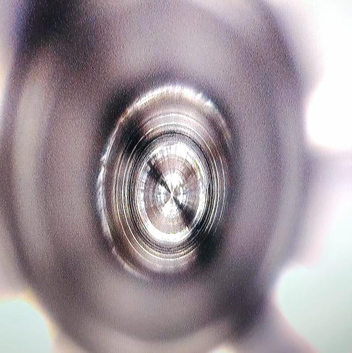
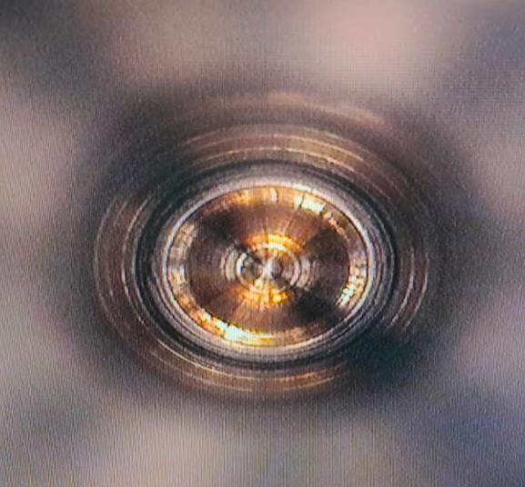
Fig- 5: PictureofNozzleSeat/Sacareawith(a)RPOil(b) CuttingFluidStain(c)RPOilStain(d)NoContamination (NoCuttingFluidStain/RPOilStain)takenwithDinolite
Microscopeat20XMagnification
3.1 Effect of Nitriding Time
Gasnitridingoperatesonatheoreticalbasisinvolvinga heterogeneous reaction between an ammonia (NH3) gas atmosphere and the surface of steel at temperatures typically ranging between 500-580°C [12]. This process entails chemical reaction, as depicted in Equation 1 Ammonia is transported to the metal surface through molecular diffusion. NH3 molecules then adsorb onto suitable surface sites and undergo sequential dissociation stages,ultimatelyproducingatomicnitrogenandhydrogen. Nitrogen diffuses into the surface, where it dissolves interstitiallyandfacilitatesthedevelopmentofironnitrides. Meanwhile, hydrogen either forms molecular H2 or reacts withoxygento generateH2O,and bothsubstancesdesorb fromthesurfaceintothefurnaceatmosphere [12] .

where [N] represents the N atom dissolved in the workpieceofthesurface.Theaboveequationpresumesthat equilibrium has been established. The activated atomic nitrogendissolvesintotheironcrystallattices,facilitating boththenitridingof��-Feandtheformationandgrowthof compoundlayers [5] Thegrowthofthecompound(nitride) layer on the surface and the formation of the nitrogen diffusion zone beneath it are controlled by the atomic nitrogen diffusivity [5] . The thickness of these layers is influencedbyseveralfactors,includingthecompositionof
thebasemetal,thedurationofthenitridingprocess,andthe temperatureemployedduringtheprocess[14] .Asshownin Figure6b,thecompoundlayer,comprisingtwoironnitride phases,namelyε(Fe3N)andγ’(Fe4N),iscommonlyreferred toasthe"whitelayer"duetoitspersistentwhiteappearance after etching with Nital. Directly beneath the compound layer lies the diffusion zone, characterized by nitrogen in solidsolutionandstablemetalnitridesformedintheshape of needles by alloying elements such as aluminium, molybdenum, chromium, and tungsten. Etching can be employed to reveal these nitrides in the form of needles, making the diffusion zone visible. The thickness of this diffusionzonewasmeasuredusingamicrohardnesstester. Theeffectivecasedepthisacrucialparameterdetermined from the diffusionzone.It representsthedistance inward from the surface of a part to a specific hardness level designatedbythedesignengineer.Toascertainwhetherthe intended hardness has penetrated to the correct depth, measurementsaretakenwithamicrohardnesstester.This measurement is essential for ensuring that the desired hardnessprofilehasbeenachievedatthespecifieddepth, validatingtheintegrityandperformanceofthetreatedpart.
In order to achieve specified ECD (0.20 mm minimum), multiple batches of injector nozzles were produced with different nitriding times (18-43 hrs). The componentsfromeachbatchwerethensubjectedtovarious quality tests to assess the impact of nitriding time on the properties of the nitride layer. Data from the DOE trial, includingECDmeasurementswerecollectedandanalyzed statistically.Statisticalanalysistechniqueswereemployedto identifytrendsandcorrelationsbetweennitridingtimeand ECD.ThelowestECDwasreportedfornitridingtime-18hrs whichwas0.22mm,ontheotherhand,thehighestECDwas reportedfornitridingtime-43hrswhichwas0.30mm.Itis observedthat,withanincreaseinnitridingtime,ECDalso increases. Based on the findings from the DOE trial, recommendationsweremaderegardingtheidealnitriding timei.e.,43hrstoachievethedesirednitridelayerquality. Figure 6 (a). illustrates the effect of nitriding time on the effectivecasedepthofthenozzle.Themicrostructureofthe nozzlenitridedfor43hrshasdevelopedaverygoodcase& uniformwhitelayerasshowninfigure6(b).
International Research Journal of Engineering and Technology (IRJET) e-ISSN: 2395-0056
Volume: 11 Issue: 06 | Jun 2024 www.irjet.net p-ISSN: 2395-0072
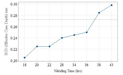
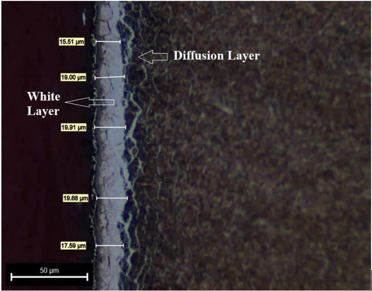
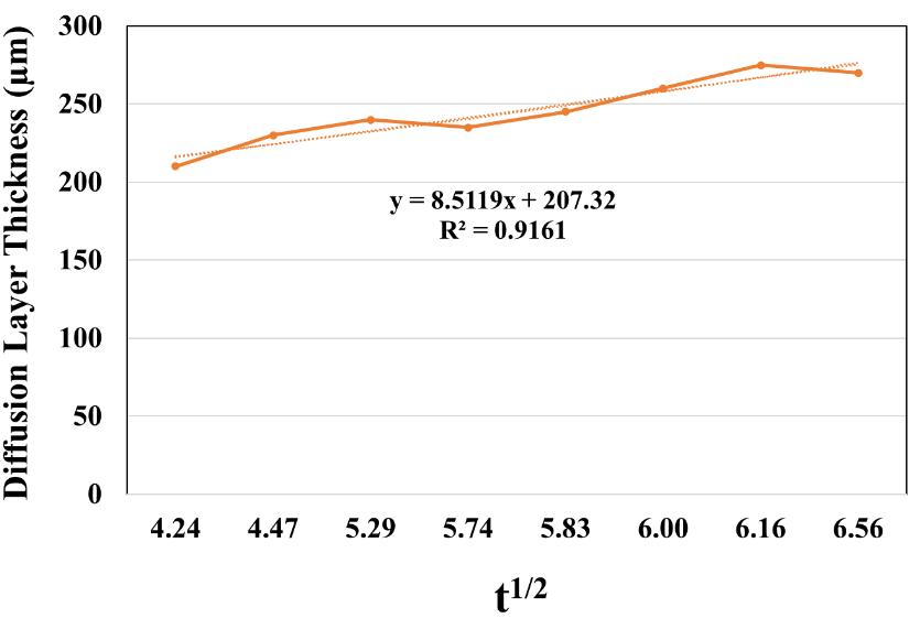
Fig-6:(a)EffectofNitridingTimeonEffectiveCaseDepth (ECD)ofNozzle(b)Microstructureofwell-developed nitridinglayercomprisingofWhitelayer&DiffusionLayer ofNozzleNitridedfor43hrsat500X(c)DiffusionLayer thicknessasafunctionofthesquarerootofthenitriding time.
Keeping in mind that nitriding is a diffusion-controlled process,thetimedependenceonthelayerthickness(d)in the gas nitriding is described thermodynamically by an equation relating the nitriding thickness to the process parameters (time and temperature in the case of gas nitriding). For gas nitriding, this equation is typically parabolicandcanbeexpressedasfollows[13]


whered-thicknessofthenitridedlayer,
t-Nitridingtime
DN-effectivediffusioncoefficientofnitrogen,which, consideringanarrhenius-typebehaviouriscalculated accordingto exp (- )


whereTisthenitridingtemperature(inKelvin),
R-Universalgasconstant,
D0-Pre-exponentialorfrequencyfactor
EA-Apparentactivationenergyofthenitridingprocess
This theoretical approach is applied ahead,and compared with the experimental results obtained in the present work (see Figure. 6 (a)). The evolution of the diffusionlayerthicknessasafunctionofthesquarerootof nitridingtimeispresentedinFigure.6(c)isstrongevidence thatthegasnitridingisadiffusion-controlledprocess.The linear relationship observed in Fig. 6c, data was also mathematically treated to estimate how close it is to the fitted regression line. The equations of the fitted straight lines and the coefficient of determination (R2) for the obtaineddatacanbeseeninEquation.(4).
y=8.5119x+207.32 [4]

=0.9161
Thefitofthelinearrelationshipswasquitegood,since R2 ≈1.
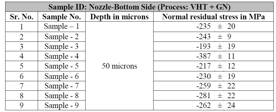
On the other hand, compressive residual stress analysiswasperformedonsamplesplacedat9-locationsof furnaceandshowedthatsufficientamountofcompressive residual stresses are developed in the diffusion zone to sustain better fatigue life during the application. Table.2 depictsresidualstressanalysisdata.
© 2024, IRJET | Impact Factor value: 8.226 | ISO 9001:2008 Certified Journal | Page777
International Research Journal of Engineering and Technology (IRJET) e-ISSN: 2395-0056
Volume: 11 Issue: 06 | Jun 2024 www.irjet.net p-ISSN: 2395-0072
Table -2: Residualcompressivestressdataof9Pole samplessubjectedtoGasNitriding.
Results confirm that the layer growth is strongly dependentonthenitridingtime,beingthislayerrelatively thicker for a longer nitriding time. The experimental data obtainedfromthenitridingofnozzles,rangingintimefrom 18hoursto43hours,revealsacleartrend:anincreasein nitridingtimecorrespondstoanincreaseincasedepth.This observation aligns with the kinetics of the gas nitriding process,wherethegrowthofthenitridinglayerthickness followsaparaboliclaw,asarticulatedinEquation(2).Itis understoodthatgasnitridingkineticsarecharacterizedbya slowprogression,necessitatingextendedfurnaceresidence timesdependinguponcasedepthrequirement.Somestudies havealsoshownthatfornitridingthegearsforwindpower plants using the zero flow method (from steels 42CrMo4, 31CrMoV9, 34CrNiMo6) with requirement of case depth layer (0.6 mm-0.8 mm) requires almost 60-80 hrs of nitriding time, whereas plates for casting glass bulbs are made from N135M steel with requirement of case depth layeras0.20-0.25mm requires26hrstoobtainsufficient case depth [11] In the realm of gas nitriding, this law postulatesthatthethicknessofthenitridinglayerincreases proportionallywiththesquarerootofthenitridingtimein gasnitridingprocesses’eitherbeitzeroflowtechnologyor vacuumtechnology.Thisalignmentoffersvaluableinsights into the kinetics of gas nitriding, deepening our comprehensionofhowvariationsinnitridingtimeinfluence theresultantcasedepthinnozzles.
3.2 Effect of Surface Contaminants on Effective Case Depth:
AsshowninFigure7(a),partshavingthepresenceof RPOil,CuttingOilStains,Postwashingcontamination(RPoil stain/cuttingoilstain)intheseat/sacareahavesignificantly impacted ECD when subjected to heat treatment, in both locations of nozzle i.e. M (Sac) & U (Seat) location. These partsshowedlowECDrangingbetween0.00-0.15mmwhich is below the required level of specification. On the other hand, Parts with No contamination showed sufficient developmentofcasedepthintherangeof0.27to0.30mm asdepictedinFigure7(b).
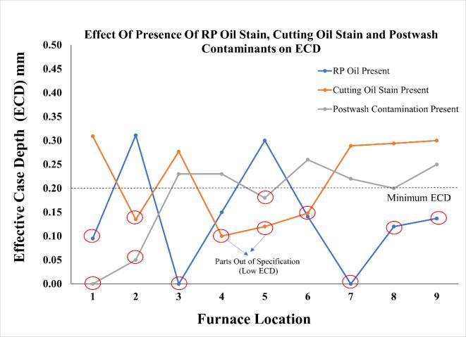
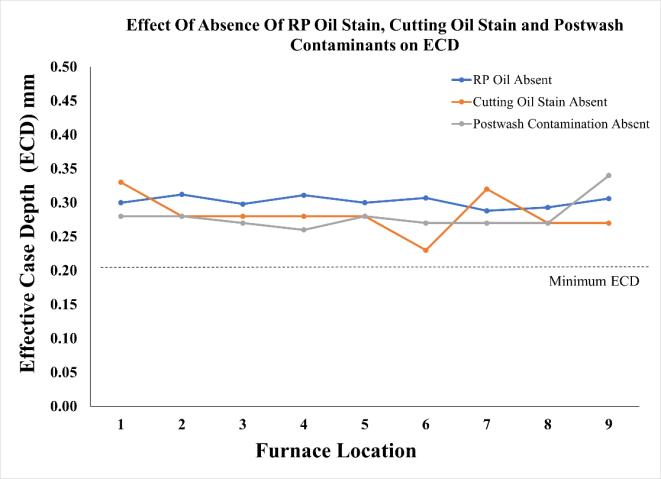
Fig-7: (a)EffectofPresenceofSurfaceContaminantson EffectiveCaseDepthofNozzleatLocationU(Seat Location)(b)EffectofAbsenceofSurfaceContaminantson EffectiveCaseDepthofNozzleatLocationU(Seat Location).
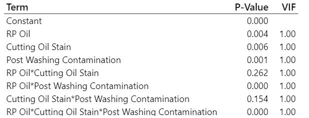
Inthecurrentstudy,designedexperimentscanbe usedtosystematicallyinvestigatetheprocessvariablesthat affect product quality. The provided data from DOE was analyzed using statistical tools to examine the correlation between RP oil, cutting oil stain, and post washing contaminants with effective case depth. Minitab software wasemployedforstatisticalanalysis,utilizingtheDOEStudy tool.Thestudyinvolvedafullfactorialanalysisconsidering three factors. The results of the statistical analysis are depictedinparetochartfigure8.Theparetochartisauseful toolforidentifyingthemagnitudeandsignificanceofvarious effects.Ontheparetochart,barsthatcrossthereferenceline are statistically significant. in figure 8, bars representing factors A, B, C, AC, and ABCcross the reference line set at 2.120. This indicates that these factors are statistically significantininfluencingtheECD.Additionally,theirPvalues
International Research Journal of Engineering and Technology (IRJET) e-ISSN: 2395-0056
Volume: 11 Issue: 06 | Jun 2024 www.irjet.net p-ISSN: 2395-0072
being below 0.05 further confirm their statistical significance,underliningtheirimpactonECD.Ontheother hand,theinteractionbetweenBC&ABi.e.cuttingoilstain withpostwashingcontamination&RPoilwithcuttingoil stainisnon-significant.
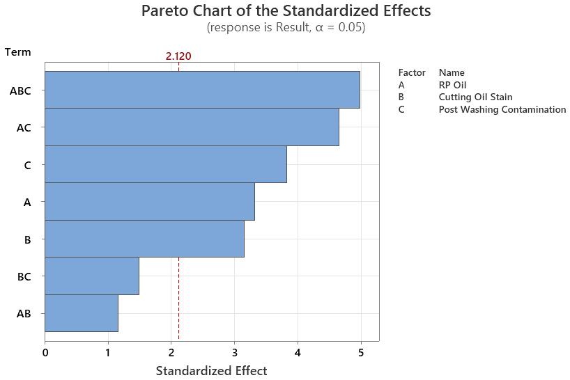
Fig-8: ParetoChartoftheStandardizedEffects.
Table -3:PvalueofEachFactor
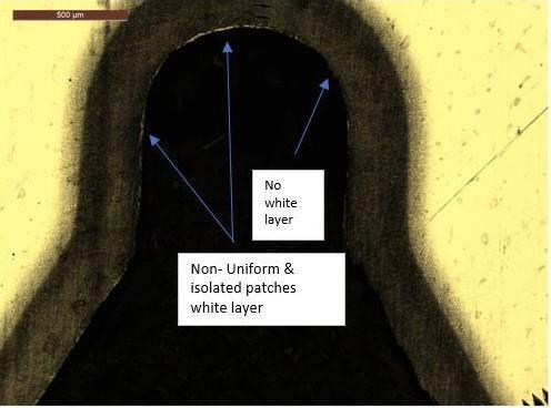
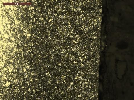
The comparative microstructure analysis of nozzles having no stain and stain was carried out. The case depth structureofpartshavingRPstainswithLowECD(0.15mm ~Below0.20mm)isshowninFigure9(a)&(b).Partshows non-uniform&isolatedpatchesofnitridinglayerconsisting ofwhitelayeranddiffusionlayerinSeat(U)&Sac(M)area. However, The case depth structure of the part having no stainwithmoderateECDof0.27mmisshowninFigure9(c) &(d).Partshowsa uniform nitridinglayerconsistingofa whitelayerandadiffusionlayer.
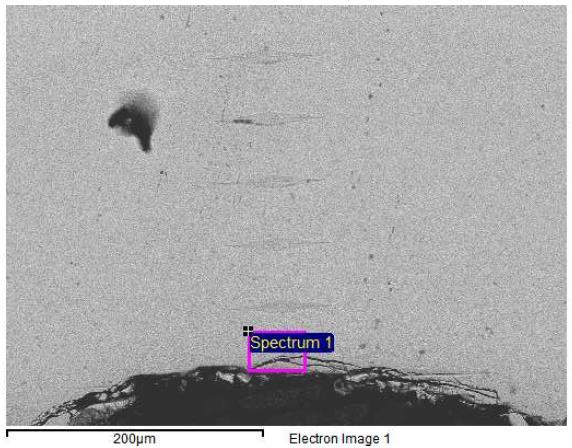
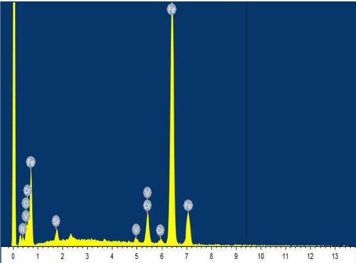
TheaboveobservationwasalsoconcludedwithSEMEDSanalysis. Nozzlehaving RPOil stainsubjectedtoheat treatmentwasmeasuredforeffectivecasedepthanalysis. Figure 9 (d). depicts a cross-sectional view of this nozzle, havinganeffectivecasedepthof0.05mmattheMlocation and0.26mmattheODlocation.EDStracesweretakenon thecasedepthregionofthenozzleattheM&ODlocation.It was observed that at M Location there is a presence of Oxygen (7.20%) with no traces of nitrogen, as shown in Table.4(a).However,atODlocation,thecaseisviceversa whereinthepresenceofnitrogenisdetectedwithnotraces ofoxygen,asshowninTable.4(b).
International Research Journal of Engineering and Technology (IRJET) e-ISSN: 2395-0056
Volume: 11 Issue: 06 | Jun 2024 www.irjet.net p-ISSN: 2395-0072
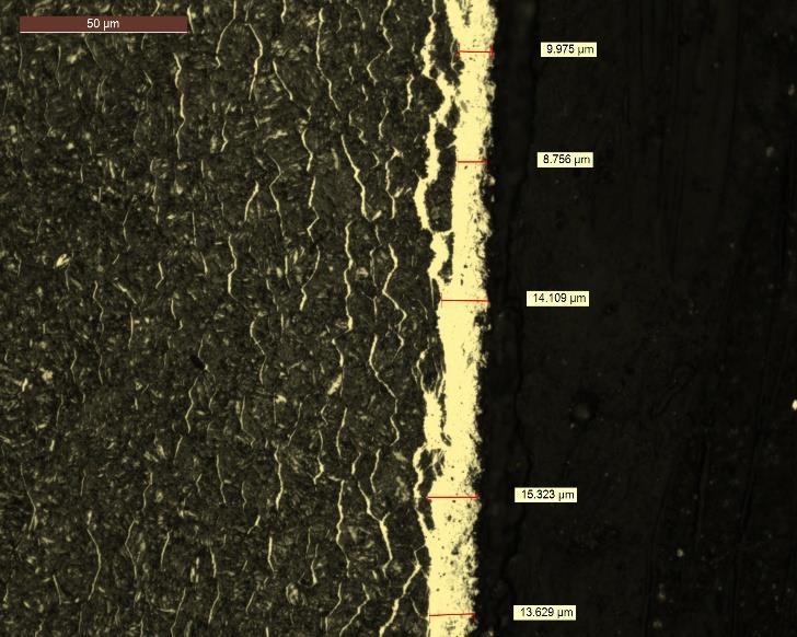
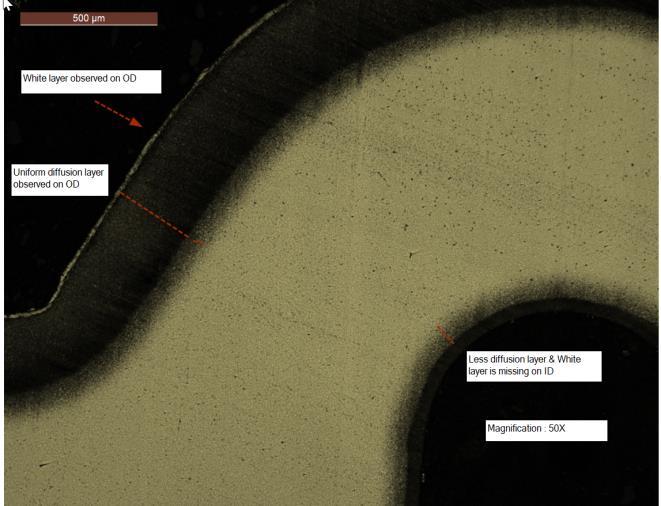
Fig-9: (a) Cross-sectional view of nozzle having RP Oil/CuttingFluidstainswithlowECD(0.15mm~Below0.20 mm)showingnon-uniform&isolatedpatchesofwhitelayer (0-11 micron) in nozzles at 50X magnification (b) MicrostructureofnozzlehavingRPOil/Cuttingfluidstains withLowECD(0.15mm~Below0.20mm) showingnonuniform&isolatedpatchesofwhitelayer(0-11micron)in nozzlesat500Xmagnification(c))Cross-sectionalviewof nozzlehavingnoRPOil/Cuttingfluidstainswithmoderate ECD 0.27 mm at 50X Magnification (d) Microstructure of nozzlehavingnoRPOil/CuttingFluidStainswithmoderate ECD0.27mmshowinguniformwhitelayer(10-12Micron)& diffusion layer at 500X magnification (d) Cross-sectional viewofnozzlehavingeffectivecasedepthas0.05mmatM location and 0.26 mm at OD location taken for SEM-EDS analysisat50Xmagnification
Table -4: SEM-EDStraceofnozzle(a)AtlocationM showingthepresenceofoxygenindicatingthepresenceof RPOilStain(b)AtLocationODshowingNoPresenceof Oxygen.
International Research Journal of Engineering and Technology (IRJET) e-ISSN: 2395-0056
Volume: 11 Issue: 06 | Jun 2024 www.irjet.net p-ISSN: 2395-0072
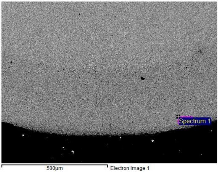
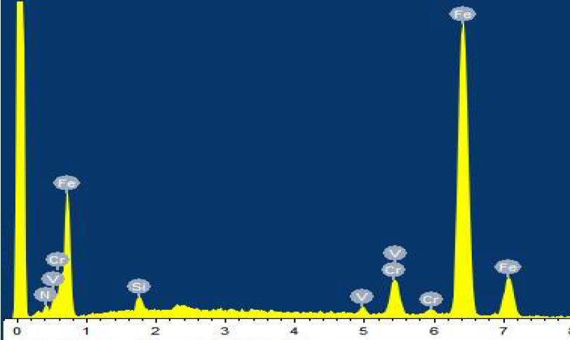
Fig-10: (a)SEM-EDSgraphofnozzleatlocationM(b) SEM-EDSgraphof nozzleatlocationOD(OuterDiameter).
Alotofworkhasbeencarriedouttounderstandthe effect of gas nitriding process parameters on nitriding propertiesinvarioussteelgrades [16][17]. Indeed,whilethe nitridingprocesshasbeenextensivelystudied,thereremain gapsinunderstanding,particularlyregardingtheeffectsof surface structure, composition, and contaminants on nitriding properties. The efficiency of the process is contingent on various factors, including the material and alloycomposition,thesurfaceshapeandcondition,andthe pretreatmentoftheworkpiece[12][15].Surfacecontaminants, such as remnants from machining, cooling lubricants, and residual protective oils like RP oil used in prior manufacturing steps, can persist on the workpiece. These contaminants pose a significant challenge to the nitriding processat multiplelevels. Someof the studiesindicated a strong influence of surface contamination on the rate of nitrogenacceptance [12][15]. Itisobservedthatnon-volatile contaminants and reaction layers such as phosphates, silicates, and sulfides are stable and hinder gas nitriding duringthewholeprocessperiod;itisthereforenecessaryto remove these from the surface before Nitriding [12]. The
results also indicated a strong negative influence of machining cutting oil over the nitriding properties, i.e. nitrogen adsorption, leading to a heterogeneous aspect of the parts and a lowering of mechanical properties [12]. If surface contaminants are volatile such as tenside desorb from the surface during gas nitriding [12]. Lightly bonded contamination layers can easily be removed by liquid cleaningprocesses.Stronglybondedreactionandadsorption layers cannot unfortunately be reduced by conventional cleaning,andsowhentheseareformed,othermethodsmust befound [12] .Thistheorycorrelateswiththecurrentstudy wherein parts having the presence of RP Oil or RP Stains (Grade-Daubert 307HF) and cutting fluid stains (GradeEcocutHSG211HD),whichareofnon-volatilegradesactas aformidablebarriertonitrogendiffusion.Somestudieshave provedthatsuchacontaminationlayercanberemovedbyin situpre-treatment(surfaceactivation)ofthesurfacebefore nitriding, enabling it to reach the reference nitriding properties,evenforsamplesthatarehighlycontaminated [15]
As a result, based on microstructure, SEM/EDS, microhardness & statistical analysis it is evident that the diffusion of nitrogen has been affected by the presence of surfacecontaminants. Thepresenceofsurfacecontaminants actsasabarrierfornitrogendiffusion,impedingtheprocess of forming a robust nitriding layer and, consequently, limiting the attainment of an adequate case depth. Conversely, parts free from any surface contaminants demonstrate a positive outcome, showcasing a welldevelopedcasedepth.Insummary,thepresenceofcertain non-volatilesurfacecontaminantscansignificantlyimpact the gas nitriding process, emphasizing the importance of maintainingacleansurfaceforoptimalnitridingproperties andachievingthedesiredcasedepth.
1)Thedurationforwhich componentsareexposedtothe nitriding atmosphere is a crucial factor in the nitriding process.NitridingtimedirectlyaffectstheECD,representing the depth to which nitrogen atoms have diffused into the material. A longer nitriding time is associated with an increased ECD, leading to enhanced surface hardness and improved wear resistance. This correlation highlights the significance of optimizing nitriding parameters, including time, to achieve the desired material properties and performanceoutcomesinthetreatedcomponents.
2)Surfacecontaminants,suchasRPoilstains and cutting fluidstains,especiallywhentheyarenon-volatile,cancreate a barrier that interferes with the smooth and uniform diffusionofnitrogenintothematerial.Theconsequenceis unevennitriding,potentiallyleadingtovariationsintheECD across the component's surface. Therefore, thorough cleaningofthepart'ssurfaceorensuringitisfreefromany contaminationiscrucialbeforesubjectingittogasnitriding. This emphasis on cleanliness is essential for achieving
International Research Journal of Engineering and Technology (IRJET) e-ISSN: 2395-0056
Volume: 11 Issue: 06 | Jun 2024 www.irjet.net p-ISSN: 2395-0072
consistent and desired nitriding outcomes, including uniformECDandoptimalmaterialproperties.
Acknowledgment
TheauthorsextendtheirsincereappreciationtotheMaterial Science Testing Lab, Manufacturing, Quality & Production Team ofCumminsFuel Systems,India(CFSI),and Kalyani Technoforge Limited (KTFL). Special thanks go to Vishal Khutale,IshantBhoskar,NandakumarS,GaneshKhumkar, Sakshi Gite, Anant Andhale, Vitthal Chungiwadar, Prasad Walunjkar, Rohit Karadge, and Shilpa Ghawate for their valuablecontributionsandsupport.
Credit Authorship Contribution Statement
Madhuri Thombre: Conceptualization, Formal analysis, Investigation,Writingandediting-originaldraft.
Rajeev Arora, Prasanth Karakavalasa : Methodology, Funding acquisition, Supervision, Project administration, Resources.
1. AbhishekBalasahebShinde,OmkarAnilUmadi,ShivajiV Gawali,ArunKamble,InternationalResearchJournalof Engineering and Technology (IRJET), 7, 3095-3102 (2020)
2. Min-Seop Kim, Ugochukwu Ejike Akpudo, Jang-Wook Hur., Journal of the Korean Society of Manufacturing ProcessEngineers,10,1-16(2021)
3. AmirH.Shamdani,AmirH.Shamekhi,M.Z.Basharhagh, S. Aghanajafi, Modeling and Simulation of a Diesel EngineCommonRailInjectorinMatlab/Simulink,("4th Annual ( Mechanical Engineering Conference, Isfahan UniversityofTechnology2006)p.1-7.
4. Şeyda Polat, Ş. Hakan Atapek, Fatih Gümüş, GAS NITRIDING OF A HOT WORK TOOL STEEL AND ITS CHARACTERIZATION, (International Iron & Steel Symposium,Karabük,Turkey,2012)p257-263.
5. E. J. Mittemeijer, M. A. J. Somers, Journal of Surface Engineering,13,483-497(1997)
6. N.Sylaa,F.Aliaja,B.Dalipi,ACTAPHYSICAPOLONICAA, 130,83-86(2016)
7. O.Irretier,C.Naber,J.Dong,H.Klumper-Westkamp,B. Haase,K.Bauckhage, SurfaceEngineering,12,331-334 (1996)
8. K. Genel, Mehmet Demirkol, Surface & Coating Technology,195,116-120(2005)
9. B. Guillot, S. Jegou, L. Barrallier, Surface & Coating Technology,316,59-70(2017)
10. TomaszPrzygoński,ZEROFLOW®GASNITRIDINGISA MODERN TECHNOLOGY THAT MINIMIZES THE CONSUMPTION OF PROCESS MEDIA AND REDUCES EMISSIONSOFPOST-PROCESSGASES.
11. S.S.Akhtar,A.F.M.Arif,BekirSamiYilbas,International JournalofAdvanceManufacturingTechnology,47,687698(2009)
12. SyedSohailAkhtar,AbulFazalM.Arif,BekirSamiYilbas, International Journal of Advance Manufacturing Technology,58, 57-70(2011)
13. Maciej Korecki, Michal Bazel, Michal Sut, SECO/WARWICKS.A.;PiotrKula,EmiliaWolowiec,LPC and LPN of Tool Steel Fuel-Injection Nozzles,( Lodz UniversityofTechnologyPoland,2014),p39-42.
14. KOWALSKA, J., MAŁDZIŃSKI, L., Combustion Engines, 167,3-7(2016)
15. Kowalska, J., & Małdziński, L., ZeroFlow - new, environmentally friendly method of controlled gas nitriding used for selected car parts, (OP Conference Series:MaterialsScienceandEngineeringPoland2016), p1-10.
16. Qiang, L., & Sugiyama, T. "Heat Treatment Method for FuelInjectionNozzleofEngineFuelSystem",Accessed 11Feb2020.
17. Małdziński,L.,Tacikowski,J.,ThermochemicalSurface EngineeringofSteels,459-483(2016)


SeniorSupplierQuality ImprovementEngineerat CumminsFuelSystemsIndia.
SupplierQualityLeaderat CumminsFuelSystemsIndia.
MaterialScienceLeaderat CumminsEngineComponents, India.