
Performance Prediction using Exploratory Data Analysis with the Attitude Parameters of a Quadcopter
Darshit
Dhake1 , Himanshu Rawat2 , Swapnil Mohanty3 , Shardul Mehetar4
1-2Students, Dept. of Computer Science, Lokmanya Tilak College of Engineering, Navi Mumbai, Maharashtra, India
3Student, Department of Ceramic Engineering, National Institute of Technology Rourkela.
. 4Student, Dept. of Computer Science, Terna Engineering College, Navi Mumbai, Maharashtra, India
Abstract- Drones are widely used in the world for various applications ranging from a drone racing and until surveillance purposes. The performance of a drone could be predicted using exploratory data analysis thereby they could be maintained for safe and reliable field operations. Various techniques are being conducted in the industry to predict the performance of the drone in the industries. One such analysis would be the using the attitude parameters collected from the SD card of any flight controller used in quadcopters. Exploratory Data Analysis is applied to the obtained parameters and results are further compared for prediction of safe operation and unsafe operations for the next flight. We perform post flight analysis, where in the information is obtained from data flash log files when loaded in the mission planner software. The extracted data is sent into EDA model which predicts the reliable operation by using the mode function in the dataframe.
Keywords-Drones, Exploratory Data Analysis, Performance prediction
I. INTRODUCTION
The drones these days are integrated to several applicationsinthecurrentscenariorangingfromracingto surveillance. Incorporation of better performance is in high demand in these days when it comes to a fact of havingfull missionflights.Inthispaper, wetalk aboutthe attitudeparametersthatareoutfromaPDcontrollerused inthequadcopter.Thecoptertakenintotheconsideration is the micro drone customized based for the purpose of hobbyist flying. Here the intention of the pilot is to learn thedronepilotingandhenceitisimportanttoknowifthe drone would fly the very next time. The drone has Ardupilot based Pixhawk cube flight controller and the parametersareaccessedviatheMissionPlannerSoftware. Post flight analysis is done using the telemetry and data flash log files. Data flash logs are preferred as the communication between the air unit and ground unit remains established throughout the mission flight. The parameters from the dataflash log files cannot be viewed initiallyastheyhave.binorbinaryformat.Inordertohave avisualizationoftheparameterstheyareconvertedto.log format through the file convert options available in the mission planner software. Here as attitude analysis is performed, we are interested to look upon the data under
ATT parameter in the binary file. The binary file is fed as inputtothepythoncodewhichcontainstheprogramming to extract data under sub parameters like des_roll, roll, des_pitch, pitch, des_yaw, yaw, time etc. We are more particular in understanding the patters of the actual and desiredvaluesofroll,pitchandyawvalues.Theseattitude parameters are controlled using the quadcopter's motor speeds. By adjusting the speeds of the motors in various combinations,thequadcoptercanachievethedesiredroll, pitch, and yaw angles. To maintain stable flight, the attitude control system constantly monitors the quadcopter's orientation and makes adjustments as needed The following process is followed under two different scenarios. One where there was a smooth flight duringthemissionandthesecondwhentherewasacrash during the mission. The endurance of flight in both the cases is about 14.5 minutes. Exploratory Data Analysis is performed in both the cases and the performance of the flight is predicted further. This paper is divided into differentsections.Thedronewascustomizedasdescribed in [1]. The description of the paper gets initiated by considering the quadcopter dynamics as in [2]. This is describedinsectionII.SectionIIItalksaboutthesoftware requirements for this project. Mission planner, python, UAV Log Viewer along with other packages need to be installed in the python environment in order to get the required results. Section IV, talks about the approach towardstheprojectorthepseudocodeoftheexecutionof the python program. Section V talks about the discussions upon the results achieved. Further in section VI future worksarediscussed.
Quadcopters
Flying machines or air vehicles are generally classified based on the way the wings are mounted. Hence an aerial vehicle could be either fixed wing, e.g., airplanes, or rotating wing, e.g., helicopters. A multi-rotor helicopter with the ability to VTOL is known as a quadrotor or quadcopter.Fourrotorsliftthemandmovethemforward. They are classified as rotorcraft among aircraft since they areliftedandpropelledbyagroupofrotors.Twoidentical fixed pitch propeller pairs, two rotating in the clockwise (CW) and two in the counter-clockwise (CCW) directions, areusedbyquadcopters.Theseregulateliftandtorqueby varying RPM. Computer/electronic systems can regulate the motion of the vehicle by altering the torque load and International Research
International Research Journal of Engineering and Technology (IRJET) e-ISSN: 2395-0056
Volume: 11 Issue: 05 | May 2024 www.irjet.net p-ISSN: 2395-0072
thrust/liftcharacteristicsofoneormorerotordiscs,which alterstheirrotationrate.

Figure 1: QuadcopterUnderConsideration
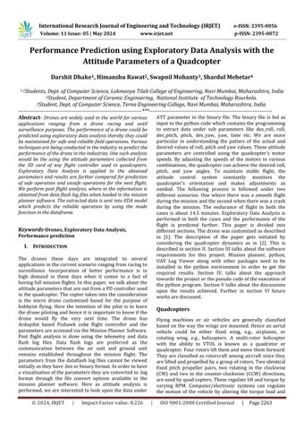
A simple quad rotor is constructed through mechanical components such as frame and fixtures, electric motors and electronic components such as electronic speed controllers, sensors, on board microprocessor, batteries and GPS. Some of the sensors include the Inertial MeasurementSensorscalledasInertial Measurement Unit (IMU) which is the combination of gyroscope (to measure the direction) and accelerometer (to measure the acceleration).Thealtitudesensorprovidestheinformation about the height of the quadrotor from the ground and is achieved through SONAR. The Bluetooth or the telemetry ortheWi-Fiservestocommunicatebetweenthequadrotor and the ground station. In case of indoor navigation, the GPS cannot provide accurate data and so the LASER sensors play a vital role for enabling the navigation by generating a local map for the purpose of finding the position of the quad rotor. This process is actually called Simultaneous Localization and Mapping (SLAM). Some of the controllers used for the autonomous navigation are PIXHAWK, APM etc. The need for these controllers is to provideadequateinterfacesforstabilizingtheautonomous motion of the copters. The computing for the navigation processcouldbeachievedeitheronboardoroffboard.The algorithmisimplementedintheon-boardprocessorinthe former case or in the ground station in case of off board processing.
CONTROL THEORY & M
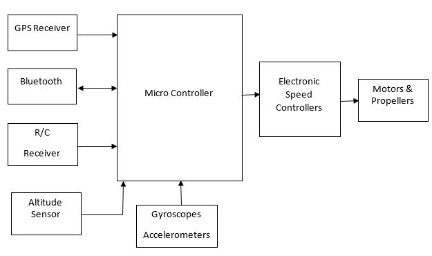
The propellers and motors are the main components that enable the flying operations of the quad rotors. Although they are chosen identical, the manufacturing defects associatedmakethembehaveina different wayreflecting in the rotation rates of each of the rotor. Signals from microcontrollerarethePWMsignalsappliedtoeachofthe motors do generate different forces causing irregular rotation rates. Figure 3 shows the driving scheme employed in quadrotors. Therefore, the system requires the introduction of a control feedback scheme in order to decrease the error between the desired and measured valueoftherotorspeeds.
QUADCOPTER DYNAMICS
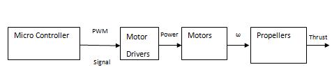
The block diagram depicted in figure 1 can serve as a representation of the drone under consideration's overall control architecture. The nested feedback loop is madeup oftheinnerattitudeandoutsidepositioncontrolloops.
Figure 4: Positionandattitudecontrolvianested feedbackloops
Dynamic Modelling and Analysis
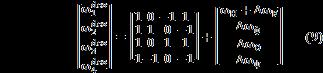
Figure 5 depicts the exact free body and systems of drone underconsideration.Itcomprisesofthefixedworldframe (W),towhichthedrone'scenterofmassattachesthebody frame.Tosimulatetherotatingmovementofthequadrotor in the W frame, the Z-X-Y Euler angle convention is utilized. We rotate via Zxy by yaw, then about the intermediatex-axisbyroll,andlastlyabouttheYb bypitch togetattheBframe.Asaresult,therotationmatrixRfrom theWtoBframeisberepresentedasfollows:
Figure 2: BlockDiagramofaquadcopter
ODEL EQUATIONS-NEED
Figure 3: Motor/PropellerDrivingScheme
International Research Journal of Engineering and Technology (IRJET) e-ISSN: 2395-0056
Volume: 11 Issue: 05 | May 2024 www.irjet.net p-ISSN: 2395-0072
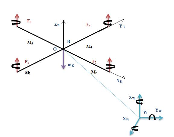
Figure 5: FigureoftheOverallFreeBody
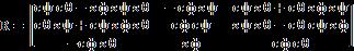
wheresineandcosinearerepresentedbytheletterssand c,respectively.Ifristhecentreofmass'positionvectorin the W, then equation describes the center of mass acceleration
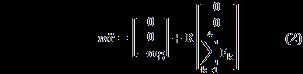
inertia) matrix, I, is linked by center of mass, is produced by weighing the constituent parts of the quad rotor. In termsofangularacceleration,
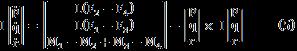
TheangularvelocitycomponentsforthedroneintheBare p, q, and r. The rotor moments caused by the rotors' angularvelocityaregivenby (6)
When the nominal thrusts are equivalent to the force of gravity, the hovering process takes place and is provided by (7)
Themotorspeedthenwouldbe:

Attitude Control

Where ,
The quadrotorhasa massofm., whileg isgravitycausing acceleration. r,q and p stand for the angular velocity of robot in B. The following diagram illustrates the relationship between the pitch,yaw angles and roll in relation to these derivatives.

Motor Control
As a result of rotation by the rotor, a vertical force Fk is generatedandisgivenby,
Eachrotor'sMk momentisparallel torotatingplaneofthe blades. Rotors 3 and 1 generate moments in the – Zb direction. Moments are produced in the direction of Zb by rotors 2 and 4. With M3 and M1 acting in the Zb direction and M4 and M2 acting in the different directions, then quadrotor creates a moment that acts in the opposite direction to the direction the blades rotate. L denotes the separation betweentherotor’s rotationaxis andCentreof the quadrotor. The XB-YB-ZB axis, the MI(moment of
Attitudeparametersareessentialaspectsofaquadcopter's control system that determine its orientation and stability in three-dimensional space. A quadcopter has six degrees of freedom: three rotational (roll, pitch, and yaw) and three translational (surge, sway, and heave). The attitude parameters specifically refer to the rotational aspects, whichareroll,pitch,andyaw.
Roll: Roll refers to the rotation of the quadcopter around its longitudinal axis, which is an imaginary line running from the front to the back of the vehicle. When the quadcopter rolls, one side of the vehicle moves upward whiletheothersidemovesdownward.
Pitch: Pitch is the rotation of the quadcopter around its lateral axis, which is an imaginary line running from one side of the vehicle to the other. When the quadcopter pitches, the front of the vehicle moves either up or down relativetotheback.
Yaw: Yaw is the rotation of the quadcopter around its vertical axis, which is an imaginary line running from top to bottom. Yawing changes the direction the front of the quadcopterisfacingwithoutaffectingitsposition.
Four distinct propeller speeds are input to the controller. The quadcopter's dynamic model is used to design the PD controller. Given that the associated vectors may be considered to be linearly combined, the desired rotor
International Research Journal of Engineering and Technology (IRJET) e-ISSN: 2395-0056
Volume: 11 Issue: 05 | May 2024 www.irjet.net p-ISSN: 2395-0072
speeds are given by replacing (4) and (6) in (5), as illustratedbelow:
When the desired angular velocities for each rotor where(k=1,2,3,4), and hovering speed is . The proportional-derivative control rules govern the deviationsthatoccurinpitch,yaw,roll,andnetforcealong thez-axis,whicharecomputedas.
II. SOFTWARE USED
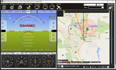
Mission Planner:
Mission Planner can be used to configure the autonomous vehicle or as an extra dynamic control strategy. Here are someexamplesofhowMissionPlannermightbeused:
• Install the firmware (software) for the Pixhawk series autopilotboardthatrunstheautomobile.
• Set up, fine-tune, and setup the drone for optimal performance.
• Using simple point-and-click way-point entry on Google or other maps, plan, save, and load autonomous missions intoyourautopilot.
• Load and study the logs of mission generated by your autopilot.
( )+

Command of position
To enable the drone to follow the desired course ri,T, the acceleration in command is based on the position inaccuracyandderivedfromthePDcontroller. (11)
Where (i=1,2,3) are, respectively, drone's 3-D position and the planned trajectory. You should be aware that forhover.Thevehicle'sorientationmust be set close to zero throughout the duration of the flight. The motion equation that describes the common hover statescanbelinearizedtoproducethiseffect.
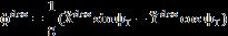
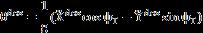
The value of nominal hover state (r= , ф=θ=0, ѱ=ѱT, ). Pitch and roll angles should not significantly alter while the aircraft is in flight. The requisite roll angles and pitch to produce motion is determined from equation (11) about these notional hoveringstatesasindicatedbythefollowingequation: (12)
Where and are the intended X and Y accelerations.ѱTistargetedyawanglethesameastheyaw anglethatwillbetracked
UAV Log Viewer:
Unmanned aerial vehicles (UAVs), often known as drones, produce logs, which are analyzed and visualized by the softwareprogramknownastheUAVLogViewer.ForUAV operators,engineers,andresearchers,thistoolisessential forgaininginsightsonflightperformance,sensordata,and othercrucialinformationgatheredduringUAVoperations. Following are UAV Log Viewer's primary roles and objectives:
Log Analysis: Theprogramexamineslogfilesproducedby UAV flight controllers and extracts information on factors such as motor outputs, GPS coordinates, sensor readings, andflightcharacteristics.
The UAV Log Viewer transforms raw log data into illustrativedisplayslikegraphs,charts,andmaps.
Gyroscopes, accelerometers, magnetometers, barometers, and other sensors' sensor data are all examined by the application. To maintain steady flight, it is essential to comprehendhowtheUAVinteractswithitssurroundings. Mission Planning: This helps to improve mission planning forefficiencyandprecision.
Figure 6: MissionPlannerSoftware-Homepage
International Research Journal of Engineering and Technology (IRJET) e-ISSN: 2395-0056
Volume: 11 Issue: 05 | May 2024 www.irjet.net p-ISSN: 2395-0072
Regulatory Compliance: For professional and research purposes, UAV flight operations may need to adhere to regulatory guidelines. UAV Log Viewer can assist in documenting flight data for compliance and reporting purposes.
ResearchandDevelopment:Engineersandresearcherscan utilize UAV Log Viewer to gather data for improving UAV designs, testing new algorithms, and developing autonomousflightsystems.
Theoutputorpilot'svisualizationoftheflightthatcrashed whileonmissionisshowninfigure7below.
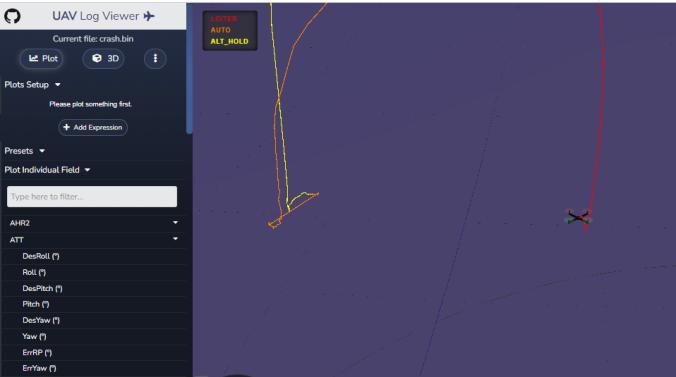
Figure 7:UAVLogviewerOutline
Python Environment:
Visual Studio Code is used as an IDE(Integrated Development Environment) to implement the corresponding programs using python containing the listedpackagesarePandas,Numpy,Matplotlib,Scipy,Path, andPymavlink
III. EXPLORATORY DATA ANALYSIS
Exploratory analysis with drone data involves the use of unmannedaerialvehicles(drones)tocollectvarioustypes ofdata,suchasimages,videos,andsensorreadings,forthe purpose of gaining insights and understanding about a particular area or subject. Due to the distinctive perspectiveandin-depthdatathatdrones cansupply;this strategy has become widely popular in a variety of fields. Thefollowingisasummaryofsignificantpointsregarding exploratoryanalysisusingdronedata:
Data Gathering Drones have cameras, sensors, and other data collection equipment that allow them to gather data fromaperspectivethatisdifficultforpeopletoreach.They might gather data from multispectral imaging, thermal imaging,LiDARscanning,andvisualdata
Applications: There are numerous uses for drone-based exploratory analysis. It is utilised in agriculture for yield estimation, disease diagnostics, and crop monitoring. In environmental study, drones are used to track animals,
© 2024, IRJET | Impact Factor
spot deforestation, and examine natural calamities. Urban planning is aided by aerial assessments of construction sitesandinfrastructure.
DataProcessing:Thedataacquiredbydronesisfrequently large and needs specialised processing. Image stitching, geo referencing, and 3D reconstruction are all standard techniques for converting raw data into useful representations.
Drones make extensive spatial analysis possible. They are capable of producing high-resolution maps and models that highlight patterns, anomalies, and changes in the terrain, which can benefit in decision-making and planning.
Drones are more cost-effective and efficient than traditional data collection methods such as piloted flights or ground surveys. They can cover wider regions in less time.
Environmental Monitoring: Drone-based exploratory analysisiscriticalforenvironmentalmonitoring.Theycan measurepollutants,habitathealth,andecologicalchanges, allofwhichcanhelpconservationefforts.
Dronesplaya keyroleincheckingessential infrastructure suchasbridges,electricitylines,andpipelines.Theylower humandangerwhileprovidingprecisevisualdata.
Regulatory limits, privacy issues, and technological limitations in terms of battery life, data transfer, and poor weather conditions all pose hurdles to drone-based exploratoryinvestigation.
Integration with AI: Integrating artificial intelligence and machinelearningalgorithmswithdronedatacanautomate tasks like object detection, anomaly identification, and imageclassification,enhancingtheefficiencyofanalysis.
FuturePotential:Astechnologyadvances,dronesarelikely to become even more sophisticated and capable of gathering diverse data types. This will lead to expanded applications across sectors and improved accuracy in analysis.
ThestepsinvolvedindevelopmentofEDAimplementation isenumeratedasshown
Loadthebinaryfileinthemissionplannerandget it converted to log file for the purpose of reference.
Load the binary file in the code and collect the requiredparameters.
IV. STEPS INVOLVED AND PROPOSED ALGORITHM
International Research Journal of Engineering and Technology (IRJET)
Volume: 11 Issue: 05 | May 2024 www.irjet.net
From the collected parameters extract the required data of actual and desired roll, pitch and yawvalues.
Performexploratorydataanalysis,preferablyEDA (ExploratoryDataAnalysis)andsavethedataina csvoranexcelfile.
Observethepatternsand predictifdronecrashis likelytooccur.
Thebinaryfileisgivenasinputtothepythonprogram. The pymavlink package associated with the flight controller extracts the requirements in the form of parameters containing des_roll, des_pitch, des_actual, Error_roll, error_pitch and error yaw. The data now is extracted to a table using the pandas package associated with python. Further the table is checked fornullvaluesandinfvalues.Inourcase,therewasn’t any.Thenthenextprocesswastofindthegainorloss margin between them. But when in particular cases whereactualvaluesanddesiredvalueswheredivided one by the other yielded infinite values. Hence their difference was considered. Their differences were plotted on a separate column. The algorithm for roll, pich and yaw values after observing the threshold limits are presented in the following table 1. It the obtained difference values were found to cross the threshold limits then negative (-1) is assigned and if notpositive1(+1)isassigned.Themodeofthisseries is considered as final output. If the mode of the series is-1thenthedronehashighchancestocrashthevery next flight is attempted. In case +1 is the output then prediction predicts for safe operation for the next flight.
Table 1: Thethresholdlimits
V. RESULTS & DISCUSSION
The results for a full non crashed mission could be seen below in the figure below. It describes the difference in roll, pitch and yaw values. Following figure shows the result of the crashed drone flight. The difference plotted againstthetimeinstancesindicateda highermarginvalue inthedifferencevalues.Thetable2liststhepredictionfor themissionflightwithcrashandwithoutcrash.
Table 2: PredictionTable
Normal Mission Flight Results:
Thefollowingfigurescorrespondtothe
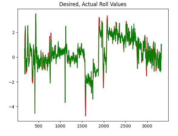
Figure 8: AttitudeRollParameters
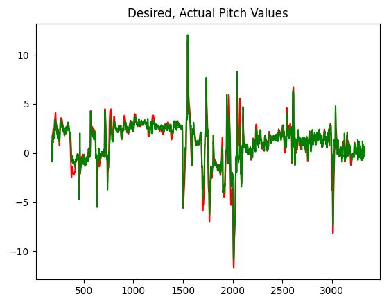
9: AttitudePitchParameters
Figure
International Research Journal of Engineering and Technology (IRJET) e-ISSN: 2395-0056
Volume: 11 Issue: 05 | May 2024 www.irjet.net p-ISSN: 2395-0072
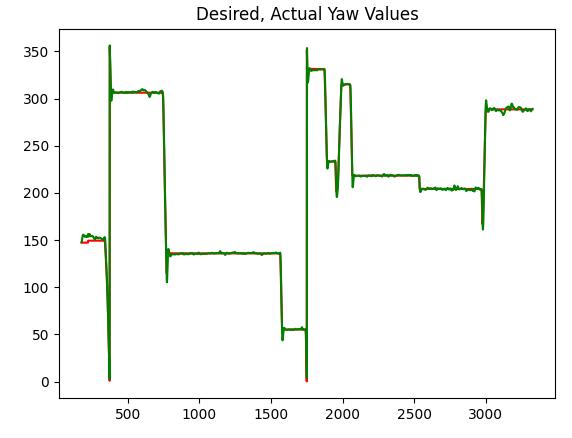
10: AttitudeyawParameters
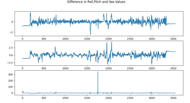
Figure 11: AttitudeRoll,PitchandYawDifference
Crashed Mission Flight Results:
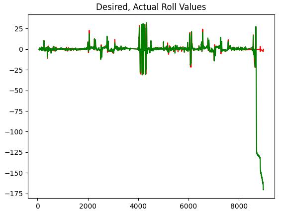
Figure 12: AttitudeRollParameters
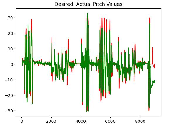
Figure 13: AttitudePitchParameters
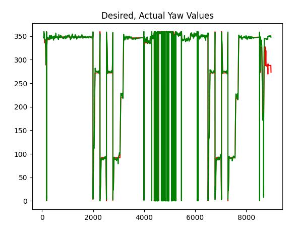
Figure 14: AttitudeYawParameters
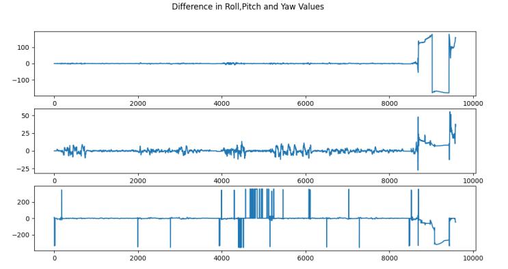
Figure 15:AttitudeRoll,PitchandYawDifference
VI. CONCLUSION
In conclusion, we have performed exploratory data analysis over the data extracted from dataflash log files. This is a post flight analysis and not a real time analysis. The extracted data fed to analysis model where in thresholdlimitsaredefinedfortheirdifferenceinattitude parametervalues.Theresultsarefurthershowninresults
Figure
International Research Journal of Engineering and Technology (IRJET) e-ISSN: 2395-0056
Volume: 11 Issue: 05 | May 2024 www.irjet.net p-ISSN: 2395-0072
column. The threshold limits defined can be referred to table1forfurtherimplementationprocess.
VII. REFERENCES
[1]Bouabdallah,S.,&Siegwart,R.(2007).Full control ofa quadrotor. In Proceedings of the 2007 IEEE/RSJ International Conference on Intelligent Robots and Systems(IROS)(pp.153-158).
[2] Mellinger, D., & Kumar, V. (2011). Minimum snap trajectory generation and control for quadrotors. In Proceedingsofthe2011IEEEInternational Conference on RoboticsandAutomation(ICRA)(pp.2520-2525).
[3] Lee, T. D., Leoky, M., & McClamroch, N. H. (2010). Geometric tracking control of a quadrotor UAV on SE (3). IEEE Transactions on Control Systems Technology, 18(3), 679-686.
[4] Faessler, M., Franchi, A., & Scaramuzza, D. (2017). Differentialflatnessofquadrotordynamicssubjecttorotor drag for accurate tracking of high-speed trajectories. IEEE TransactionsonRobotics,33(6),1464-1477
[5] Mahony, R., Kumar, V., & Corke, P. (2012). Multirotor aerial vehicles: Modeling, estimation, and control of quadrotor. IEEE Robotics & Automation Magazine, 19(3), 20-32.
[6] Bresciani, T., & Chatila, R. (2013). Robust visual servoing for UAVs. IEEE Transactions on Robotics, 29(1), 33-46.
[7]Ma,J.,&Hovakimyan,N.(2016).Adaptivebackstepping control for quadrotor attitude and position tracking. JournalofIntelligent&RoboticSystems,84(1),227-244.
[8] Ryll, M., Sieberling, S., Bülthoff, H. H., & Giordano, P. R. (2013). A modeling approach for quadrotor vehicles subject to rotor aerodynamics. In AIAA Guidance, Navigation, and Control Conference (p. 4676). American InstituteofAeronauticsandAstronautics.
[9]ExploratoryDataAnalysisinRemoteSensing"byLu,D., &Weng,Q.(2007)
[10] "UAV-based Remote Sensing for Urban Vegetation Mapping Using Random Forest and Texture Analysis" by Wang,L.,Sousa,W.P.,&Gong,P.(2014)
[11] "Unmanned Aerial Vehicles for Urban Air Quality Measurements" by Zhang, C., Wu, Y., Yang, F., Zhang, J., & Xia,X.(2016)
[12] Drones in Environmental Science: A Review" by Anderson,K.,&Gaston,K.J.(2013)
© 2024, IRJET | Impact Factor value: 8.226 |
[13] Drones in Environmental Science: A Review" by Anderson,K.,&Gaston,K.J.(2013)
[14] "The X-Y-Z Approach for Graphical Data Analysis" by Cleveland,W.S.(1993)