
International Research Journal of Engineering and Technology (IRJET) e-ISSN: 2395-0056
Volume: 11 Issue: 05 | May 2024 www.irjet.net p-ISSN: 2395-0072
International Research Journal of Engineering and Technology (IRJET) e-ISSN: 2395-0056
Volume: 11 Issue: 05 | May 2024 www.irjet.net p-ISSN: 2395-0072
S.T.Amin1 , S.M.Abbas2 , A.Usmani3
1Research Scholar, Corresponding Author, Department of Civil Engineering, JMI, New Delhi
2Professor, Department of Civil Engineering, JMI, New Delhi, India
3 DGM, ETDD, EIL, New Delhi
Abstract - The significance of tunnel construction has elevated manifold owing to its diverse applications in contemporary transportation and communication infrastructures. Nonetheless, the seismic susceptibility of these underground structures is of utmost concern due to their vulnerability to different forms of damage. Consequently, this article undertakes a static and seismic analysis of an existing tunnel, both in the absence and presence of an additional new tunnel of same diameter, positioned vertically below the existing tunnel at different spacing. A 2D plain strain soil-tunnel model is created using Finite element analysis software GTS NX Midas. The characteristics of the soil are similar to the alluvial silts found in Delhi and the earthquake selected for seismic analysis is the Loma Preita earthquake. Response-spectra compatibleearthquakedataisproducedusingSeismoMatch software. The response parameters obtained from the results are in the form of forces generated in the existing tunnel lining such as axial force, bending moment, shear force, and contours depicting ground displacement. From static analysis, it is observed that due to a new tunnel, the lining forces in the existing tunnel decrease, whereas with increase in distance between the two tunnels, the existing tunnel of the twin tunnel system behaves similar to the single tunnel. However, during seismic analysis, there is negligible difference between the single tunnel and the existing tunnel of the twin tunnel system after a certain distance. Therefore, it can be understood that the seismic stability of the existing tunnel is independent of the vertical spacingofthenewtunnel.
Key Words: plane strain, twin tunnel, alluvial silts, static and seismic analysis.
Thebeginningofundergroundtunnelstracesbackto2200 B.C. Since their inception, these tunnels have served different purposes in transportation and communication. The ever increasing urbanization has led to a scarcity of available aboveground space for further expansion of communication networks and utility services. Consequently,inthecontemporaryera,thereisagrowing demand for underground structures, particularly tunnels,
to cater to various developmental requirements. Over the years, there has been a prevailing assumption that the underground structures offer greater seismic safety compared to their aboveground counterparts, attributed totheinherentrestraintprovided bythesurroundingsoil or rock. However, a multitude of incidents has demonstrated significant tunnel damage resulting from seismic events. Hashash [1] has cited several case studies whichhighlighttheneedfor enhancedseismic designand mitigation strategies to bolster the structural integrity of tunnelsinearthquake-proneregions.
Seismic waves can induce significant structural impacts beyond those anticipated for an isolated tunnel due to a new adjacent opening. Research has been performed to anticipate the induced stresses in pre-existing tunnel structuresduringseismicevents,especiallyaccountingfor the excavation of a neighbouring tunnel [2]. However, simpler approaches by Corigliano [3] have been found to yieldgoodresultsforseismicanalysisofdeeptunnels,but anextensiveassessmentofthedynamicgrowthofinternal stresses on the lining is essential for stable design in seismicallyactivelocations.Thestudylooksatavarietyof analyticalmethodologies,includingsimpleproceduresand advanced numerical simulations, to estimate the seismic stress increment and the reliability of pseudo-static solutions Also, Bobet performed a research [4] that introduced new mathematical methodologies for evaluating the effect of pore water pressure on tunnel stability under static and seismic loading. The research investigates the drainage conditions at the ground-liner interface, as well as the impact of groundwater pressure on ground and support reactions. Similarly, the study carriedoutin[5]focusesonseismicanalysisofdeeptwin tunnels in Indian cities such as Delhi, taking into account specific soil properties and using a pseudo-static approach. The study quantifies the additional moments, thrusts, shear, and surface displacements caused by earthquake stresses on the tunnel liner, highlighting the needofincludingseismicloadingintotwintunneldesigns. Wang [6] determined the maximum bending moments using the full-slip closed form solution and compared to those obtained by no-slip finite difference analysis. The full-slip assumption resulted in higher bending moments than the no-slip assumption. The full-slip assumption
International Research Journal of Engineering and Technology (IRJET) e-ISSN: 2395-0056
Volume: 11 Issue: 05 | May 2024 www.irjet.net p-ISSN: 2395-0072
resulted in somewhat more ovaling (distortion) of the lining, while the differences were insignificant. There is another research [7] which focuses on the effect of constructing an additional tunnel, either horizontally or vertically aligned, on the response of the existing tunnel. The analysis is conducted in both static and seismic conditions by altering the pillar width between the tunnels. The study shows that following an earthquake, vertical stresses at critical areas and forces in the tunnel lining of horizontally aligned twin tunnels gradually increase for a pillar width equal to half the tunnel’s diameter. The vertical strains and forces in the first tunnel'sliningincreasewithrespectto pillarwidth.Bazaz andBesharat[8]investigatedtheseismicstudyofshallow tunnels in a soil medium, with particular focus on the behaviour of circular cross-section tunnels during operation, by comparing numerical findings with analytical responses provided by Penizen and Wang. The results show a relative error in the analytical approaches, and increasing soil stiffness reduces the resulting circular stressinthelining.Thisisalsoprovedinanotherstudy[9] which states that the axial force in the tunnel lining decreasessignificantlyassoilcementationimproves.Also, a decrease in tunnel axial forces results in oval distortion intunnelsegments,althoughadecreaseinshearforceand bending moment benefits the tunnel structure. Similarly, the interaction of parallel tunnels and the amplification influence on surface acceleration are particularly important during a seismic event. The interaction of parallel tunnels considerably impacts the distribution of internal force and the magnitude of neighbouring surface acceleration [10]. The influence of the underground structureonsoilreactivityissignificantlydependentonits depth, but has a significant impact on the surface in the range of around five times its width [11]. Also, the alignment of a new tunnel in a twin tunnel instance has a significant impact on the variance of stresses and settlementsaroundtheexistingtunnel.Anotherstudy[12] determined the relative positions of twin tunnels using numerical analysis in three directions: horizontal alignment, vertical alignment, and inclined alignment. Settlementstudieswereconductedonthetunnelsinthese chosenorientationsundervariousloadingconditions.The construction of the upper tunnel led to a greater settling and bending moment. Vertically oriented tunnels had the most soil settling, whereas horizontally aligned tunnels hadtheleast.Horizontaltunnelexperimentsrevealedthat asthedistancebetweenthetwotunnelsincreased,surface soil settlement decreased. Beyond a certain distance, the building of the first tunnel had no bearing on the second tunnel. Similarly, the study by Hamdy [13] examined the effects of seismic waves on tunnel systems, particularly single and twin tunnels. Four cases were simulated, one for a single tunnel and three for twin tunnels. The horizontal, vertical, and diagonal alignments of twin tunnelswereinvestigatedtobetterunderstandtheimpact of seismic waves. The study found that following an
earthquake, the tunnel lining experienced significant displacement, with shear force being the most impacted, followed by bending moment. Seismic activity has a less influence on the normal force of tunnel lining. It is clear that both static and seismic analysis of twin tunnels is critical, since the structural integrity of underground structures cannot be overlooked, particularly in seismicallyactiveareas.
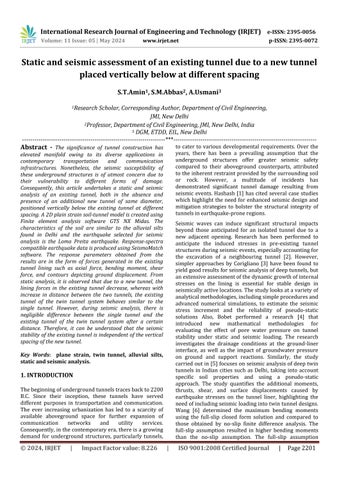
In this research article, a2D plain strain soil tunnel model is created using GTS NX Midas (Finite Element Analysis software). The cross-section of the model is of 180X100m and has seven different layers with varying modulus of elasticity, modified from [14]. The variationof modulus of elasticity along with the depth of soil is taken intoconsiderationasshowninTable1.Elasto-plasticMohrColoumbsoilconditionischosenfromallthelayersofsoil. Thevariouspropertiesofsoilconsideredforthestudyare listed in Table 2. The dimensions of tunnel are such that the diameter of the existing tunnel(D) is 6.26m [14] and thedepthofthetunnelis46.87mfromthegroundsurface. 1D beam elements are selected for the tunnel to simulate linear behaviour of the tunnel lining. The dimensions of beam element used are 1X0.3m. The existing tunnel comprises of 40 such bending elements. No slip condition is considered between the tunnel lining and the surrounding soil. No groundwater table condition is considered for any layer of soil. Damping of 10% and 5% are assigned to each layer of soil and tunnel lining respectively. The importantproperties of the tunnel lining are thereby mentioned in Table 3. A new tunnel of same diameter is considered for the vertical twin tunnel system asshowninFigure1.Here,thedistanceofthenewtunnel, XD isvariedat1.5D 2D,2.5D,3Dand3.5Dfromthecentre of the existing tunnel.(D =diameter of the existing tunnel and the new tunnel). In total, 6 different models are created.
After assigning the soil and tunnel properties, the model comprising of single tunnel and twin tunnel are finelymeshedusing4-nodedquadrilateralelementsuptoa maximum size of 1m. A high quality mesh is created to achieve the required accuracy, convergence, reduce the time and thereby expedite the process of simulation. The tunnels are meshed initially followed by the multiple soil layers.Themeshoftunnelliningisextractedfromthesoil excavationmesh
International Research Journal of Engineering and Technology (IRJET) e-ISSN: 2395-0056
Volume: 11 Issue: 05 | May 2024 www.irjet.net p-ISSN: 2395-0072
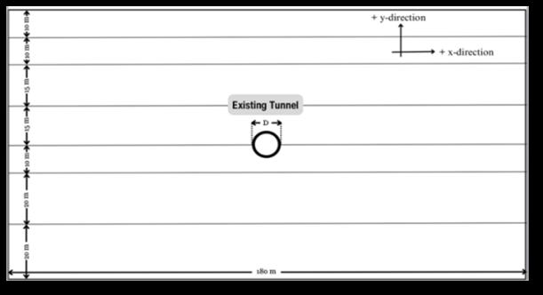

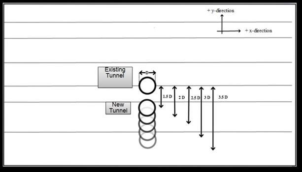

Figure-1: Schematic layout of soil-tunnel model with (a) single tunnel (b) twin tunnel


Mesh diagram

LomaPreitaearthquake(1989)isselectedfortheseismic anlysis.SinceDelhifallsinseismic zoneIV(IS1893:2002, [15]), it is important to generate an artificial earthquake which is compatible for Delhi soils (alluvial silts) to generate realistic ground responses. Hence, with the help of SeismoMatch software response spectra compatible time history data is produced using Loma Preita earthquake data as shown in Fig.3. The original Loma Preita earthquake had a PGA of 0.367g whereas the artificial earthquake has a PGA of 0.125g. This artificially generated time history data has a total time period of 40sec. The earthquake is applied horizontally to the soiltunnel model for a time duration of 12 seconds to fasten the computational process of the analysis as it is the predominanttimeperiodoftheearthquake.
Figure-3: Loma Preita earthquake accelerogram

Propertiesofeachsoillayer{modifiedfrom[14]}
Depth (m)
Table-1: Mechanicalpropertiesofsoil[14]
Properties
Values
Unitweight,γbulk 18kN/m3
Saturatedunitweight,γsat 20kN/m3
Cohesion,c 0
Frictionangle,Φ 35ᴼ
Dilatancyangle,Ψ 5ᴼ
Poisson’sratio,ν 0.25
Table-3: Propertiesoftunnellining[14]
Properties
Values
Diameterofthesingle/existing tunnel,D 6.26m
Overburdendepth,H 46.87m
ThicknessofRCliners 0.28m
XD (Centre to centre distance/ Diameterofthetunnel) 1.5to3.5
ElasticmodulusofRCliners,EC 3.16X10⁷ kPa
Poisson’sratioofconcrete 0.15
2.3 Analysis Procedure
For static analysis,all vertical boundary nodes are hinged inthexdirectiontoallowforunhinderedmovementinthe y-direction. The bottom border isfixedinall directionsto simulate bottom rock condition. This is followed by Eigen valueanalysis,wheregroundsurfacespringsareassigned to the soil model only. Now in case of seismic analysis, absorbentboundariesareplacedattheverticalbordersto replicate free field ground conditions. Various steps involvedinthewholeanalysisarementionedbelow:-
International Research Journal of Engineering and Technology (IRJET) e-ISSN: 2395-0056
Volume: 11 Issue: 05 | May 2024 www.irjet.net p-ISSN: 2395-0072
Step1:Tocreateinitial stresses,theat-rest earthpressure coefficient,"Ko condition" is considered by activating all soillayers.Thesoilexcavationandliningarenotactiveat thisstage.
Step2: Soil from the first tunnel is removed. Volume contraction of 3% is used to represent the proportion of ground loss volume during excavation. The tunnel liner is assembled at the same time to prevent the tunnel cavity fromcollapsing.
Step3:Samestepasmentionedin Step2 isrepeatedforthe newtunnellocatedataparticularverticaldistance.
Step4: Static analysis is carried out for the whole system and the resulting stresses get stored as the initial stress conditionpriortotheoccurrenceofearthquake.
Step5: Eigen value analysis is performed to generate dominant modes of frequencies, which are used to calculate mass and stiffness proportional coefficients, α andβrespectively.
Step6: Non-linear time history analysis is performed by incorporating α and β from Step5 and applying the artificially produced Loma Preita earthquake in the + xdirectiontothesoil-tunnelmodel.
Static and seismic results produced in the existing tunnel lining after the construction of the new tunnel are presented in the form of lining forces such as axial force, bending moment, shear force and ground displacement contoursofthesurroundingsoilmedium.
The process of constructing a new tunnel requires the removal of the soil from its pathway. The removal of ground followed by the installation of tunnel lining alters the overall load distribution mechanism of the surrounding soil. This causes redistribution of stresses in the soil medium, which are then stored as initial stresses priortotheexcavationofanewtunnel.So,thepurposeof this research study is to determine the impact of constructing this new tunnel on the existing tunnel lining andthesurroundingsoilmedium.
Static loads on tunnel linings, such as soil pressure and structural weight, are critical factors for assuring structural stability, safety, and long-term performance. Proper analysis through forces such as axil force, bending moment and shear force helps in efficient and reliable designofthetunnels.
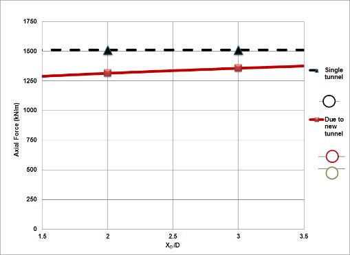
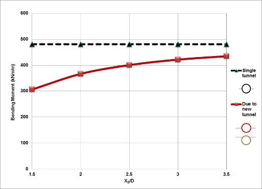
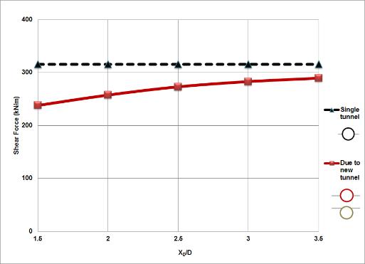
Figure4(a)showsthevariationofaxialforcewithrespect toXDintheexistingtunnellining,whereXDistheratioof centre-to-centre distance between the tunnels and the diameter of the tunnel (D). The variation of bending moment and shear force in the existing tunnel lining also
showasimilarpatternasshowninFigure4(b)and4(c).It can be understood that due to construction of a new tunnel, the lining forces decrease in the existing tunnel in comparison to a single tunnel. This may be due to distribution of loads between the two tunnels, thereby generating lesser forces in the existing tunnel lining. Secondly, there is increase in lining forces increase with increase in XD. The gradual reduction of load sharing mechanism between the two tunnels as the soil bridge betweenthemincreasesmayleadtothispattern.Itcanbe seenfromthegraphsthatasthedistancebetweenthetwo tunnelsincreases,theliningforcesoftheexistingtunnelin case of twin tunnel system slowly approach the values of thesingletunnel.


(a) (b)
(c)

Figure-4: Variation of (a) Axial Force (b) Bending Moment (c) Shear Force in the existing tunnel lining due to construction of new tunnel

International Research Journal of Engineering and Technology (IRJET) e-ISSN: 2395-0056
Volume: 11 Issue: 05 | May 2024 www.irjet.net p-ISSN: 2395-0072
Due to static loads, there occurs probable ground deformation which may result in different settlement patterns around the tunnels and the surrounding soil medium.Hence,itbecomesimperativetoanalysedifferent displacement contours for proper analysis and efficient design.
Figure5showsthedisplacementcontoursincaseofsingle tunnelandtwintunnelwhenanewtunnelispositionedat 1.5D,2.5Dand3.5Dfromtheexistingtunnel.Itcanbeseen that due to construction of a new tunnel, several displacement contours of same magnitude get shared betweenthetwotunnelswhenthenewtunnelisplacedat 1.5Dfromtheexistingtunnel.Butasthedistancegradually increases from 2.5D to 3.5D, the contours get divided betweenthetwotunnels.AlsoasshowninFigure5(a),the position of maximum total displacement is located at the crownofthesingletunnel.However,incaseoftwintunnel system,thispositionofmaximumtotaldisplacementshifts to the crown of the new tunnel for each distance from the existingtunnel.
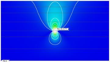

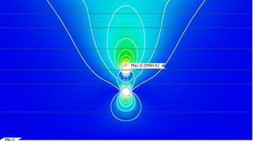

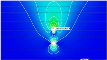

Figure-5: Variationofgrounddisplacement contoursincaseof(a)singletunnelandanew tunnelof(b)1.5Dand(c)3.5D

Figure 6 depicts the contours of axial force, bending moment and shear force in the existing tunnel when the newtunnelisplacedat2.5D.Thepositionofmaximumaxial force with the highest magnitude is located at the left springline of the existing tunnel and is of compressive nature. Similarly, the position of maximum bending moment is located at the right springline of the existing tunnel and is hogging in nature. The position of maximum shear force is located at +45º to the left springline of the existingtunnelandispositiveinnature.
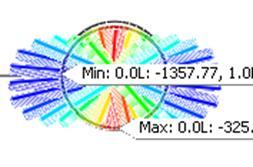

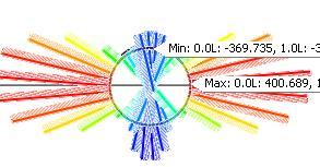


Figure-6: Contours of (a) Axial Force (b) Bending Moment (c) Shear Force in the existing tunnel

The single and the twin tunnel models are then seismically analyzed by non-linear time history analysis withthehelpofLomaPreitaearthquake.Thetunnellining forces of the existing tunnel and ground displacement contoursarecompared.
3.2.1
Thevariationofliningforcesinthesingletunnelandtwin tunnelunderearthquakearecomparedinFigure7.Asseen in Figure 7 (a), the variation of axial force in the single tunnel and existing tunnel in case of twin tunnel isalmost same. Axial force generally depends on the overburden stress from the soil on the tunnel lining which does not undergo any significant change due to the horizontally appliedearthquake.Hence,thereisnegligibledifferencein the variation of axial force between the single tunnel and twintunnelundertheseismicload.
However,incaseofbendingmomentandshearforce,there is a slight increase in existing tunnel of the twin tunnel systemas comparedtothesingletunnel.Thedifferencein the values of the forces is very low and is significant only when the distance between the two tunnels is 1.5D to 2D.
International Research Journal of Engineering and Technology (IRJET) e-ISSN: 2395-0056
Volume: 11 Issue: 05 | May 2024 www.irjet.net p-ISSN: 2395-0072
Itcanbeobservedthatwhenthetwotunnelsareextremely close to each other, the existing tunnel in case of twin tunnel experiences greater seismic load as compared to a single tunnel. This may be attributed to the fact that there is an increase in the interference of stresses between the twotunnelsunderthehorizontalearthquakeload.Also,as the distance between the two tunnels exceeds 2D, it is noticed that the vertical positioning of the new tunnel belowtheexistingtunnelisofnotmuchsignificancetothe existing tunnel under earthquake. Hence, it can be concluded that in case of earthquake, the performance of theexistingtunnelisindependentofthenewtunnelwhen placedbelowitatdifferentspacing.
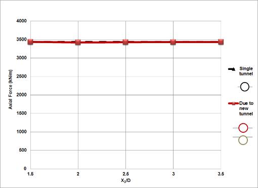

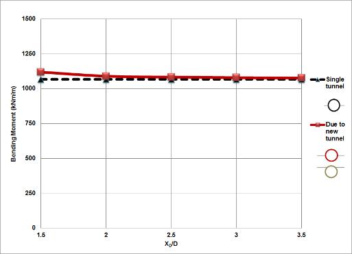

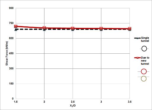

Figure-8: Variation of (a) Axial Force (b) Bending Moment (c) Shear Force in the existing tunnel lining after earthquake

Figure 9 shows the various displacement contours of the single tunnel and the twin tunnel when the new tunnel is placedat1.5D,2.5Dand3.5Dfromtheexistingtunnel.Itis observed from Figure 9 (a) to 9(b) that under the influence of earthquake, the soil medium around the twin tunnel experiences a lot of disturbance as compared to a single tunnel. Also, as the distance between the two tunnels increases, the soil around the new tunnel undergoes greater displacement contours due to the experienceofgreaterverticalload.
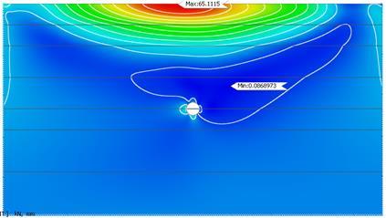

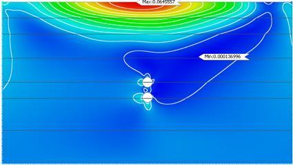

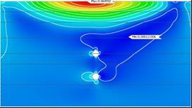

Figure-9: Variationofgrounddisplacement contoursin(a)singletunnelandnewtunnel isat(b)1.5Dand(c)3.5D

Figure 10 represents the contours of axial force, bending momentandshearforceintheexistingtunnelwhenanew tunnel is placed at 2.5D from it. The position of greatest magnitudeofaxialforceshiftstotherightspringlineofthe existing tunnel and is compressive in nature as compared tothestaticcase.Butincaseofbendingmomentandshear force,thepositionremainssame.Figure10(b)showsthat
International Research Journal of Engineering and Technology (IRJET) e-ISSN: 2395-0056
Volume: 11 Issue: 05 | May 2024 www.irjet.net p-ISSN: 2395-0072
thepositionofmaximumbendingmomentislocatedatthe rightspringlineofthe existingtunnel.Similarly,Figure 10 (c) shows that the postion of maximum positive shear forceislocatedat+45ºoftheleftspringlineoftheexisting tunnellining.Thismaybeduetothehorizontaldirectionof the earthquake as the earthquake impacts the existing tunnel fromthe+x-directionandhence,theeffectismore atthoselocations.

(a) (b) (c)


Figure-10: Contours of (a) Axial Force (b) Bending Moment (c) Shear Force in the existing tunnel lining after earthquake

From the results of static analysis, it can be understood that after the distance of 2.5D, the difference in variation of all the parameters between the existing tunnel and twin tunnel gradually decrease. However, in case of seismic analysis, the variation between single tunnel and the existing tunnel in twin tunnel decreases after2D.Itisessentialtofindasafedistancebetweenthe existing tunnel and the new tunnel to ensure static and seismic stability.Hence,accordingtothecurrentresearch article, an optimum distance of 2.5D-3D between the existing tunnel and a new tunnel will be ideal to be both statically and seismically safe. The result is largely dependentontheoutputofstaticanalysis.
Tunnels are very essential underground structures which require comprehensive research, especially in an earthquake-prone zone to avoid any kind of risk to possibledamageduetoanyseismicload.Therefore,inthis
article, static and seismic comparisons of a single and a twintunnelsystemarecarriedout.Theimpactisobserved on the existing tunnel due to a new tunnel of same diameterwhenplacedatdifferentverticaldistancesbelow the existing tunnel.Artificiallyproduced responsespectra compatible Loma Preita earthquake data is used in the non-linear time history analysis. The interaction effect is studiedintheformofparameterssuchasliningforcesand ground displacement contours. Based on the above research,itcanbeconcludedthat:
Incaseofstaticanalysis:
• Afterconstructionofanewtunnel,liningforcesof the existing tunnel such as axial force, bending moment and shear force decrease as compared to a single tunnel. This is due to distribution of vertical loads after constructionofthenewtunnel.
• Lining forces of the existing tunnel tend to increase on increasing the distance between the tunnels. This results from gradual reduction in load sharing mechanism from the increasing soil bridge between the tunnels.
• Displacement contours are initially shared betweenthetwotunnelsbutasthedistancebetweenthem increases,theygetdistributedbetweenthetwotunnels. Incaseofseismicanalysis:
• Axial force in a single tunnel is similar to that in the existing tunnel of a twin tunnel system. This may be due to lack of much significant difference in overburden stress on the existing tunnel lining from the horizontally appliedearthquake.
• But, the bending moment and shear force of twin tunnel system are higher than the single tunnel when the distance between the two tunnels varies from 1.5D to 2D. Beyond 2D, these forces in the existing tunnel of the twin tunnel behave similar to that in the single tunnel. Hence, after a distance of 2D, the behaviour of existing tunnel is independent of the vertical positioning of the new tunnel belowitunderahorizontalearthquakeload.
• Under the seismic load, the soil around the twin tunnel experiencesgreater disturbancesascomparedtoa singletunnel.Also,asthedistancebetweenthetwotunnel increases, the soil around the new tunnel undergoes greaterdisplacementsascomparedtotheexistingtunnel. Based on this research study, it can be concluded that an optimumdistanceof2.5D-3Dwillbeidealforconstruction of a new tunnel of same diameter vertically below an existing tunnel to counter both static and seismic loads safely.
The authors would like to thank GTS NX MIDAS India for granting access to the software and thereby complete the researchwork.
International Research Journal of Engineering and Technology (IRJET) e-ISSN: 2395-0056
Volume: 11 Issue: 05 | May 2024 www.irjet.net p-ISSN: 2395-0072
Y.M.A.Hashash,J.J.Hook,B.Schmidt,andJ.I-ChiangYao, “Seismic design and analysis of underground structures,”Tunn.Undergr.Sp.Technol.,vol.16,no.4, pp. 247–293, 2001, doi: 10.1016/S08867798(01)00051-7.
E.Zlatanović,V.Šešov,D.Lukić,andZ.Bonić,“Influenceof a new-bored neighbouring cavity on the seismic response of an existing tunnel under incident P- and SV-waves,” Earthq. Eng. Struct. Dyn., vol. 50, no. 11, pp.2980–3014,2021,doi:10.1002/eqe.3497.
M. Corigliano, L. Scandella, C. G. Lai, and R. Paolucci, “Seismic analysis of deep tunnels in near fault conditions: A case study in Southern Italy,” Bull. Earthq. Eng., vol. 9, no. 4, pp. 975–995, 2011, doi: 10.1007/s10518-011-9249-3.
A.Bobet,“Effectofporewaterpressureontunnelsupport during static and seismic loading,” Tunn. Undergr. Sp. Technol., vol. 18, no. 4, pp. 377–393, 2003, doi: 10.1016/S0886-7798(03)00008-7.
R. B. Jishnu and R. Ayothiraman, “Behaviour of Urban Metro Twin Tunnels Under Earthquake Loads,” no. July, pp. 128–140, 2018, doi: 10.1007/978-3-31961636-0_10.
J. J. Wang, “Seismic design of tunnels. William Barclay Parsons Fellowship Parsons Brinckerhoff Monograph 7,”no.June,pp.1–159,1993.
M. Singh, M. N. Viladkar, and N. K. Samadhiya, “Static and seismic analysis of twin metro underground tunnels,” Lect. Notes Civ. Eng., vol. 86, pp. 241–257, 2021, doi: 10.1007/978-981-15-6233-4_17.
J. B. Bazaz and V. Besharat, “An Investigation on Seismic Analysis of Shallow Tunnels in Soil Medium,” Proc. 14thWorldConf.Earthq.Eng.,pp.2–8,2008.
M. Azadi and M. Kalhor, “Study of the Effect of Seismic Behavior of Twin Tunnels Position on Each Other,” World Acad. Sci. Eng. Technol. Int. J. Civil, Archit. Struct.Constr.Eng.,vol.8,no.6,pp.614–616,2014.
S. Li, Y. Chen, L. Huang, and E. Guo, “Study on Response and Influencing Factors of Shield Single/Twin Tunnel underSeismicLoadingusingFLAC3D,”ShockVib.,vol. 2022,2022,doi:10.1155/2022/2224198.
F.Sun,G.B.Wang,X.J.Peng,Z.Z.Jin,X.C.Li,andJ.L.Zhao, “Seismic Response Study of Tunnels Running underneath a Subway Station in Parallel,” Shock Vib., vol.2020,2020,doi:10.1155/2020/8822981.
W. Pm Channabasavaraj and B. Visvanath, “Influence of RelativePositionoftheTunnels:ANumericalStudyon Twin Tunnels,” no. May, pp. 0–8, 2013, [Online]. Available: https://scholarsmine.mst.edu/icchgehttps://scholars mine.mst.edu/icchge/7icchge/session05/2.
H.A.A.elrahimHamdy,M.Enieb,A.A.Khalil,andA.S.H. Ahmed, “Seismic analysis of urban tunnel systems for thegreaterCairometrolineno.4,”Electron.J.Geotech. Eng.,vol.20,no.10,pp.4207–4222,2015.
M. Singh, M. N. Viladkar, and N. K. Samadhiya, “Seismic response of metro underground tunnels,” Int. J. Geotech. Eng., vol. 11, no. 2, pp. 175–185, 2017, doi: 10.1080/19386362.2016.1201881.
IS-1893-Part-1, “Criteria for Earthquake Resistant Design ofStructures - General ProvisionsandBuildingsPart1,”Bur.IndianStand.NewDelhi,vol.Part1,no.1,pp. 1–39,2002.