
International Research Journal of Engineering and Technology (IRJET) e-ISSN:2395-0056
Volume: 11 Issue: 05 | May 2024 www.irjet.net p-ISSN:2395-0072
DESIGN AND DEVELOPMENT OF WEARABLE ANTENNA FOR PROACTIVE TUMOR DETECTION
Dr. P. SURESH KUMAR, SABEEKA DEBORAH S, SHWETHA S
Professor and Head,
Final year Student,
Final year Student, Department of ECE, Department of ECE, Department of ECE, Chennai Institute of technology, Chennai institute of technology, Chennai institute of technology, Chennai -69. Chennai -69. Chennai-69.
ABSTRACT
In recent years, wearable electronics have gained opportunities and the past decade has become evidence of this growth in Wireless Body Area Network (WBAN). They fulfill the requirements of personalizing healthcare,communication,patientmonitoring,tracking, and rescue operations. The major challenge for the WBAN is tohandle the couplingof the radiator withthe human body. To increase the performance of a microstrip patch antenna, it has been blended and truncated on the diagonal sides to make up the suggested antenna design. Flexible electronics have paved the way for Wireless Body Area Networks (WBAN). This allows for optimal performance. The square patch, measuring 50 × 50 mm, resonates at the 2.4 GHz ISM band, which is frequently utilized in wireless communication applications. The FR-4 substrate, which has a relative permittivity of 4.3, was selected for the antenna. It is a lossy material with a thicknessof1.6mmanddimensionsthatmatchthoseof the ground plane (50 x 50 mm). Perfect Electric Conductor (PEC) is the material used for the patch. Its dimensions are 30 × 30 mm, or half the wavelength at the resonance frequency To further improve performance, a slot is added to the patch's center. A secondary ground plane measuring 90 x 90 mm and 2 mmthickisplacedbeneaththeprimarygroundplanein addition to the main ground plane to improve radiation efficiency and antenna stability. In order to maximize signal strength and coverage, the coaxial feed in the designiscarefullycalibratedtoimprovegain.Thedesign seekstoimproveimpedancematching,radiationpattern, and overall antenna performance by truncating and blendingthesquarepatchantenna inadditiontoadding a slot and an extra ground plane. In order to maximize efficiencyandreliabilityandsatisfythecriteriaofthe2.4 GHzISMband,muchconsiderationisgiventothechoice of materials and dimensions. The proposed antenna is designed and simulated using CST Microwave Studio software. The proposed antenna is an efficient antenna with realized gain of 2.88dBi, low VSWR and wide bandwidth.
KEYWORDS: Microstrip patch antenna, 2.4Ghz ISM band,Antennaperformance,Gain,reflectioncoefficient.
INTRODUCTION:
Wearable technology is the integration of computer and electronic technologies into everyday objectslikeclothes.Accessoriesthatcanbeworninclude fabrics, jewelry, watches, headgear, and eyeglasses. These devices include features similar to those of smartphones and PCs, in addition to providing tracking, sensing, and scanning capabilities[1]. This is a big development for ubiquitous computing since it makes information accessible from anywhere[2,3]. Among textilestructuresfeatures,built-inantennashaveshown to be an essential component of wearable technology, enabling wireless communication through clothing[4]. Among other things, wearables can be used as monitoring systems for assisted living and life care.Wearable textile systems are created when these monitoring devices are paired with textile clothing[5,6]. For a long time, antennas have been used in many different medical applications, including as medical implants, hyperthermia treatments, microwave imaging, and remote health monitoring. An antenna is, generally speaking, a device that can both receive and send electromagnetic waves [6,7].Micro-strippatchantennas arefrequently employedin communicationsystemsand search engines to establish the necessary communication links for biomedical equipment.Microstrip antennas are attractive because they are lightweight, low profile, simple to operate, and inexpensive to produce. The advantages of a small, inexpensive feed network are realized. Micro-strip antennas have been used extensively in books and publications over the past ten years[8,9]. Therapeutics and diagnostics are the two main uses for medical antennas. The antenna is either directly in contact with the skin or incorporated within the human body in therapeutic circumstances[10]. However, in diagnostic applications,theantennaiswornasawearabledeviceor placed completely outside the body, either in direct contact[11,12]. Wearable antenna concepts for biomedicalapplicationsareshowninFigure1.1.
International Research Journal of Engineering and Technology (IRJET) e-ISSN:2395-0056
Volume: 11 Issue: 05 | May 2024 www.irjet.net

Fig1.1Wearableantennaforbiomedical applications[12].
For wearable applications, textile patch antennas are the most widely used type of antenna topology among others. These antennas' flat configuration, straightforward design, versatility, lightweight, and effortless integration into any outfit make them perfect for wearable applications[4,13]. An insulating fabric substrate is incorporated into the wearablepatchantenna (WPA) designandis positioned between the conductive patch and the conductive groundplane.Furthermore,theadditionofaconductive ground plane layer reduces the possibility of skin damage from the antenna's back radiation[13,14]. Researchers face a number of difficulties in the creation andoptimisationofWPA,suchasconcernsaboutpower consumption, frequency band coverage, adaptability, compactsize,andinteractionwithtextiles.
To overcome these obstacles, it will take coordinated efforts from various research fields to develop WPA that are not only dependable and efficient but also easy to use[15]. These antennas consist of a substrate composed of a different textile material and a textile conducting element[16]. They are inexpensive, lightweight, flexible, easy to produce, and straightforward to include into a garment. In order to reducetheneedforlaborandresources,textileantennas thatcanperformavarietyoftasks,includingmonitoring, alerting, and requesting assistance if a healthcare emergency arises, are currently being developed[17]. In our work we are simulating an antenna to detect cancer.We are designing a wearable patch antenna to detectcancer.
PROPOSED DESIGN
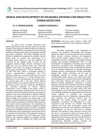
A square patch antenna that has been blended and truncated on the diagonal sides makes up the suggested antenna design. This allows for optimal performance. Thesquare patch,measuring 50× 50 mm, resonates at the 2.4 GHz ISM band, which is frequently
p-ISSN:2395-0072
utilized in wireless communication applications. The FR-4 substrate, which has a relative permittivity of 4.3, wasselectedfortheantenna.Itisalossymaterialwitha thicknessof1.6mmanddimensionsthatmatchthoseof the ground plane (50 x 50 mm). Perfect Electric Conductor (PEC) is the material used for the patch. Its dimensions are 30 × 30 mm, or half the wavelength at theresonancefrequency.
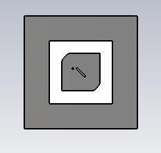
To further improve performance, a slot isaddedtothepatch'scenter.Asecondarygroundplane measuring90x90mmand2mmthickisplacedbeneath theprimarygroundplaneinadditiontothemainground plane to improve radiation efficiency and antenna stability.
In order to maximize signal strength and coverage, the coaxial feed in the design is carefully calibrated to improve gain.The design seeks to improve impedance matching, radiation pattern, and overall antenna performance by truncating and blending the squarepatchantennainadditiontoaddingaslotandan extra ground plane. In order to maximize efficiency and reliability and satisfy the criteria of the 2.4 GHz ISM band, much consideration is given to the choice of materialsanddimensions.
International Research Journal of Engineering and Technology (IRJET) e-ISSN:2395-0056
Volume: 11 Issue: 05 | May 2024 www.irjet.net
The antenna's gain is maximized by iterative design modifications and feed position optimization, guaranteeing peak performance for its intended use in wireless communication systems. Fig 4.2 and Fig 4.3 depicts the antenna design and dimension of the Antenna.Ingeneral,thesuggestedantennadesign offers a thorough method for reaching the 2.4 GHz frequency range's high performance and efficiency, which is necessary for a variety of wireless communication applications.
DESIGN PARAMETERS:
1.Calculatingthewidthofthemainpatchorradiator(W): W= √
2.Calculatingtheeffectivedielectricconstant( ): = + (1+ )
3. Calculation of the length of the main patch/radiator(L):
2ΔL ΔL=0.412h[ ]
4.Lengthofthefeedline( : =
RESULTS AND DISCUSSIONS
When examining antenna performance, a number of important factors are considered in order to determinehowwell-suitedthedeviceisforacertainuse case. Directivity, radiation pattern, VSWR (Voltage Standing Wave Ratio), realized gain, and reflection coefficient are some of the most important parameters takenintoaccount.
5.1.REFLECTION COEFFICIENT(S11):
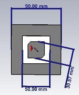
The reflection coefficient, indicating impedance mismatches in antennas, cruciallyaffects signal loss and matching efficiency. At 2.4 GHz ISM band, a low reflection coefficient, such as the measured -19 dB return loss in Figure 5.1, signifies minimal signal loss and effective power transmission into the antenna system,showcasingexcellentimpedancematching.
p-ISSN:2395-0072
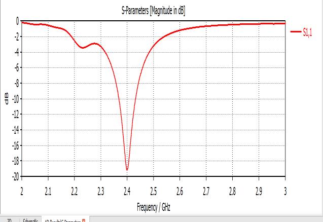
Fig5.1ReflectionCoefficient(S11)
Analyze the reflection coefficient (S11) across frequencies to assess antenna impedance behavior, particularly focusing on the 2.4 GHz ISM band. A sharp decline in the reflection coefficient curve at 2.4 GHz signifies optimal impedance matching, affirming the antenna's suitability for ISM band applications. Achieving a return loss of around -19 dB at this frequency exceeds the standard threshold of -10 dB for medicalantennas,ensuringdependableoperation.
This work assists antenna designers in finetuning parameters for optimal performance and seamless integration into the 2.4 GHz frequency band, vitalforvariouswirelesscommunicationapplications.
5.2.REALIZED GAIN:
Realized gain quantifies an antenna's efficiency in transmitting or receiving electromagnetic signals relativetoanidealisotropicradiator,consideringsystem losses. Our project yielded a realized gain of 2.884 dB, indicating intensified electromagnetic energy emission in specific directions compared to isotropic radiation. This directional concentration enhances signal strength and coverage in those specific directions, crucial for variousapplications.
The realized gain value of 2.884 dB showcases the antenna's favorable performance, surpassing the isotropicradiator'soutput. Through meticulous antenna designandtuning,thisgaincanbefurtheroptimizedfor enhanced coverage and directional effectiveness, meetingdiverseapplicationneeds.
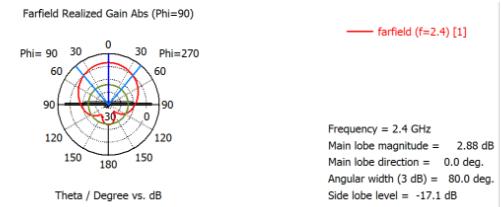
Fig5.2RealizedGain.
International Research Journal of Engineering and Technology (IRJET) e-ISSN:2395-0056
Volume: 11 Issue: 05 | May 2024 www.irjet.net
Figure 5.2 illustrates the realized gain specifically at the 2.4GHz frequency band. Our gain of 2.884dBfallswithintheidealrangeof2-6dB,affirming its suitability for antenna design purposes. This data provides valuable insights for engineers aiming to optimize antenna performance and achieve desired directionalcharacteristics.
5.3 VSWR:
VSWR (Voltage Standing Wave Ratio) measures theratioofthemaximumto minimumvoltagealongthe transmission line connected to an antenna, indicating impedancematchingandsignalloss.At2.4GHz,anideal VSWR of 1 signifies perfect impedance matching betweentheantennaandthetransmissionline,ensuring efficientpowertransferwithminimalreflection.
AVSWRof1indicatesthatallpowersenttothe antenna is efficiently transmitted, with no reflected power. This condition, known as ideal impedance matching, occurs when the antenna's impedance preciselymatchesthatofthetransmissionlineorsystem it connects to. Achieving a VSWR of 1 at 2.4 GHz in antennadesignisideal,ensuringoptimalpowertransfer efficiencyandminimalsignalloss.
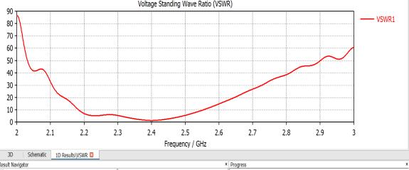
Fig5.3SimulatedPlotofVSWR
Figure 5.3 illustrates the simulated output of VSWR, providing engineers with valuable insights into antenna performance. This optimal VSWR at the intendedfrequencyvalidatestheantenna'seffectiveness for reliable wireless communication, ensuring dependableoperationandefficientpowerutilization.
5.4
DIRECTIVITY:
Directivity describes how concentrated the emitted power is in one direction as opposed to an isotropic radiator. The measurement, which is commonly expressed in decibels (dBi), indicates the antenna's ability to focus electromagnetic radiation in particular directions. Increased directivity which indicates stronger radiation in a specific direction may be advantageous for applications requiring long-range communicationorsignalidentification.InFigure5.4,the Directivitysimulatedplotisdisplayed.
p-ISSN:2395-0072
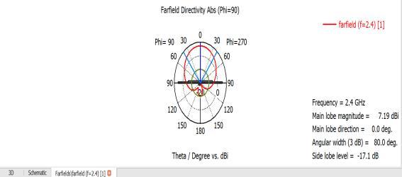
Fig5.4SimulatedPlotofDirectivity.
5.5 RADIATION PATTERN
The radiation pattern represents how the antenna sends and receives electromagnetic energy in three dimensions. Sidelobe levels, beamwidth, and antennacoveragemayallbeunderstoodwiththehelpof thisdiagram,whichdisplays thedistributionofradiated power by direction. By looking at the radiation pattern, engineers may adjust the antenna design parameters to get the desired coverage and performance features.In Figure 5.5, the output of the Radiation Pattern is displayed.
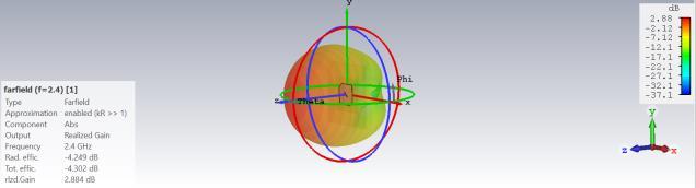
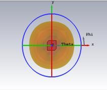
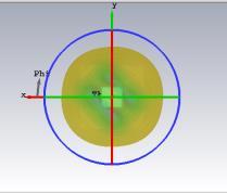
Fig5.5RadiationPatternofAntenna
CONCLUSION:
Wearable electronics, particularly Wireless Body Area Networks (WBAN), have seen significant growth, catering to healthcare, communication, and monitoring needs mainly cancer detection . Overcoming challenges like coupling with the human body, a novel microstrip patch antenna design has emerged. Featuring a 50 × 50 mm square patch resonating at 2.4 GHz, it utilizes FR-4 substrate and PEC material. Enhancements include diagonal blending, truncation, and a central slot, alongsideasecondarygroundplane.Carefulcoaxialfeed calibration improves gain and coverage. Simulated with CST Microwave Studio, the antenna achieves a realized gain of 2.88dBi, low VSWR, and wide bandwidth, ensuring efficiency and reliability with a reflection coefficientof-19dBfor2.4GHzISMbandapplications.
International Research Journal of Engineering and Technology (IRJET) e-ISSN:2395-0056
Volume: 11 Issue: 05 | May 2024 www.irjet.net p-ISSN:2395-0072
REFERENCES:
[1]Aldhaibani,J.A.,Mohammed,M.Q.,Mahmood,A.A.,& Sellab,M.(2024).Developmentofwearabletextilepatch antenna2.43GHzforbiomedicalapplications.
[2] Sabri SF, Sam SM, Kamardin K, Daud SM, Salleh N. Review of the current design on wearable antenna in medical field and its challenges. Jurnal Teknologi. 2016; 78(6-2):111-7.
[3] Daware V, Jadhav J. A review on wearable antennas. EngineeringProceedings.2023;56(1):1-7.
[4] Memon AW, De PIL, Malengier B, Vasile S, Van TP, Van LL. Breathable textile rectangular ring microstrip patch antenna at 2.45 GHz for wearable applications. Sensors.2021;21(5):1-17.
[5]Al-azzawiAA,AlmukhtarAA,HamidaBA,DasS,Dhar A, Paul MC, et al. Wideband and flat gain series erbium doped fiber amplifier using hybrid active fiber with backward pumping distribution technique. Results in Physics.2019;13:102186.
[6] Arora G, Maman P, Sharma A, Verma N, Puri V. Systemic overview of microstrip patch antenna’s for different biomedical applications. Advanced PharmaceuticalBulletin.2021;11(3):439-49.
[7] Kirtania SG, Elger AW, Hasan MR, Wisniewska A, SekharK,KaracolakT,etal.Flexibleantennas:a review. Micromachines.2020;11(9):1-43.
[8]VarmaDR,MuraliM,KrishnaMV.Designofwearable microstrip patch antenna for biomedical application with a metamaterial. In evolution in signal processing and telecommunication networks: proceedings of sixth international conference on microelectronics, electromagnetics and telecommunications 2022 (pp. 421-34).Singapore:SpringerSingapore.
[9] Palsokar AA, Lahudkar SL. Frequency and pattern reconfigurable rectangular patch antenna using single PIN diode. AEU-International Journal of Electronics and Communications.2020;125:153370.
[10]Mikulić D, Šopp E, Bonefačić D, Bartolić J, Šipuš Z. Design and realization of wearable textile slotted waveguideantennas.Sensors.2023;23(17):1-20.
[11]MerliF,BolomeyL,GorostidiF,FuchsB,ZurcherJF, Barrandon Y, et al. Example of data telemetry for biomedical applications: an in vivo experiment. IEEE Antennas and Wireless Propagation Letters. 2012; 11:1650-4.
[12] Kiani S, Rezaei P, Fakhr M. A CPW-fed wearable antenna at ISM band for biomedical and WBAN applications.WirelessNetworks.2021;27:735-45.
[13] AldhaibainiJA,YahyaA,AhmadRB,MdZAS,Salman MK. Performance analysis of two-way multiuser with balance transmitted power of relay in Lte-A cellular networks. Journal of Theoretical & Applied Information Technology.2013;51(2).
[14]BhavaniS,ShanmugananthamT.Wearableantenna for bio medical applications. In Delhi section conference 2022(pp.1-5).IEEE.
[15] Muhammad HA, Abdulkarim YI, Abdoul PA, Dong J. Textile and metasurface integrated wide-band wearable antenna for wireless body area network applications. AEU-International Journal of Electronics and Communications.2023;169:154759.
[16]PeyroteoM,FerreiraIA,ElvasLB,FerreiraJC,Lapão LV.Remotemonitoringsystemsforpatientswithchronic diseasesinprimaryhealthcare:systematicreview.JMIR mHealthanduHealth.2021;9(12):1-11.
[17] Potey PM, Tuckley K. Design of wearable textile antenna for low back radiation. Journal of Electromagnetic Waves and Applications. 2020; 34(2):235-45.
[18]Saleeb, D. A., Helmy, R. M., Areed, N. F., Marey, M., Abdulkawi, W. M., & Elkorany, A. S. (2021). A technique for the early detection of brain cancer using circularly polarized reconfigurable antenna array. IEEE Access, 9, 133786-133794.