
International Research Journal of Engineering and Technology (IRJET) e-ISSN: 2395-0056
Volume: 11 Issue: 05 | May 2024 www.irjet.net p-ISSN: 2395-0072
International Research Journal of Engineering and Technology (IRJET) e-ISSN: 2395-0056
Volume: 11 Issue: 05 | May 2024 www.irjet.net p-ISSN: 2395-0072
Shaik Firoz Basha1 , N Phani Raja Rao2
1M.Tech Student, Production Engineering Dept & Sri Venkateswara Institute of Technology, N.H 44, Hampapuram, Rapthadu, Andhra Pradesh, India
2Associate Professor and HOD, Production Engineering Dept & Sri Venkateswara Institute of Technology, N.H 44, Hampapuram, Rapthadu, Andhra Pradesh, India
Abstract – Due to their exceptional mechanical characteristics,includingeffectiveloaddistributionandhigh strength-to-weight ratio, honeycomb structures are extensively employed in a wide range of engineering applications.Thesestructuresmirrornaturaldesigns,serving as models for the development of robust yet lightweight materials. Inspired by the vascular plant Equisetum, this experimentalstudyexaminessixuniquehoneycombstructure configurations to comprehend their mechanical behavior under axial compressive loads. Using PETG reinforced with 0.5% MWCNT material, the structures were created via the Fused Deposition Modelling (FDM) technique. The axial compression behavior of these configurations was experimentally investigated to evaluate variations in mechanical performance across different geometries, highlighting the influence of structural design. The results demonstrated that the H1, H2, and H3 structures outperformed the others, indicating that structural design significantlyimpactsloaddistribution,stiffness,andresistance tocompressiveforces.Thesefindingsunderscorethepotential for optimizing honeycomb structures in engineering applicationsthroughcarefuldesign,enhancingtheiralready impressivemechanicalproperties.
Key Words: Honeycomb structures, Axial Compression, Stiffness,FusedDepositionModelling,PETG,MWCNT
Recently, honeycomb structures have been renowned for their low strength-to-weight ratio and exceptional energy absorption capabilities, making them a popular choice among researchers for their mechanical properties and acoustic and thermal behaviors [1-2] However, their evolution continues, drawing inspiration from nature and makingthemincreasinglysuitablefordiverseengineering applications. Since the 1990s, researchers have played a pivotal role in this ongoing process, exploring innovative designs and materials to enhance the performance of honeycombstructures[3-5].Researchontheoptimizationof structures with various configurations, including square, circular, triangle, and hierarchical structures, under axial
loadingconditions,hasbeenextensivelydocumented[6-7]. Recentstudiesfurtherindicatethatsmalladjustmentstothe designs of lightweight and high-strength materials can significantly enhance crushing force [8-9]. Similarly, increasingtheinwardcornersoflightweightstructureshas been shown to improve their energy absorption capacity [10]. Additionally, incorporating corners into the crosssectionoftubeshasdemonstratedanotableimprovementin absorptioncapacityresults[11].Numerousresearchershave highlighted that the geometrical changes are crucial for improving the energy absorption capabilities of these structures. This ongoing research underscores the importance of design optimization in enhancing the mechanical performance of materials used in engineering applications. However, studies under different loading conditions,suchastensile,compression,andbuckling,have been conducted over the past decades to understand the mechanicalpropertiesofthesestructures[12].Honeycomb structureshaveshownsuperiormechanicalcharacteristics, as evidenced by numerous numerical, experimental, and empiricalstudies[13].Thisongoingresearchunderscores the importance of design optimization in enhancing the mechanical performance of materials used in engineering applications.
Therefore, in this study, the six bio-inspired honeycomb structures were designed with different configurations that vary with different cell sizes and thicknesses.Wherethestructuresinspiredbythevascular plantEquisetumreplicatedandfewchangesingeometries were implemented basedontheliterature. Additionally,a plane hollow cylindrical structure was designed to understand the influence of structural design. Then all differentconfigurationswere3DPrintedandsubjected to axial compression loading conditions to understand their mechanicalbehavior.Theconclusionsweredrawnaccording totheresultsanddiscussionswerereported.
The methodology for developing bioinspired honeycomb structures commenced with the conceptualization and design of these structures, which were inspired by the
International Research Journal of Engineering and Technology (IRJET) e-ISSN: 2395-0056
Volume: 11 Issue: 05 | May 2024 www.irjet.net p-ISSN: 2395-0072
vascularsystemsofplants.Thesedesignswererefinedand modifiedbasedonathoroughliteraturereviewtoenhance their functionality and structural integrity. Using CAD software,thefinalizeddesignswerecreatedindigitalform. ThesedigitalmodelswerethenprocessedinUltimakerCura software and sliced and prepared for 3D printing. Initial tensile tests were conducted on 3D-printed specimens to ensurethedesiredqualityandmechanicalstrength,thereby validatingtheprintingparameters.Followingthisvalidation, the honeycomb structures were consistently printed with theestablishedparameters.Subsequently,compressiontests were performed on all seven different honeycomb structures.Theresultsfromthesetestsweremeticulously analyzed to evaluate and compare their mechanical performance, thereby providing insights into the effectivenessandpotentialapplicationsofthesebioinspired designs.ThemethodologyfollowedisdepictedintheFigure.
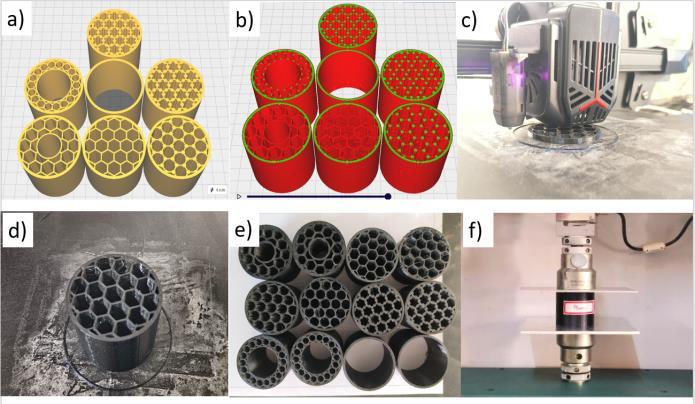
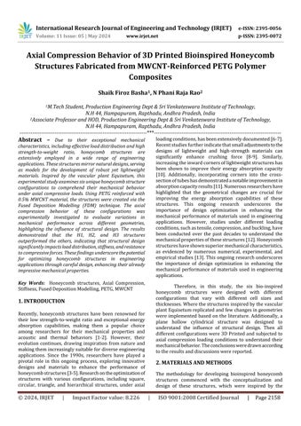
Fig -1:Methodologyofthisstudya)CADModelsb)CAD modelsafterSlicingandG-Codegenerationc)3Dprinter representingthespecimenpreparationd)Outputofthe 3D-printedSpecimene)Specimensfabricatedf)Axial Compressiontestperformedonallthespecimens.
Todesignenergyabsorptioncolumnstructuresin this study six different configurations of honeycomb cells and a plane cylindrical structure were chosen. The same external dimensions were maintained for all specimens. Initially, basic hexagonal unit cells were distributed throughoutthestructurewithawallthicknessof1mmand namedafterH5.TheH4structurewasdesignedtoreduce thesharpedgesthatjoinateachendofthehexagonalunit cell to the adjacent cell via cylindrical cells of 1.5mm diameter each. Similarly, the structure H2 inculcates cylindrical cells of 1.5mm diameter on every edge of the honeycombcells.Further,thecylindricalcellswereinserted attheedges,vertices,andjointsofeachhoneycombcellin the H1 structure. The cells consisting the cylindrical cells were prone to eliminate the sharp edges and provided a higherrelativedensitythusresultinginequalload-sharing ability.TheH6structuresimilartotheH5hadanadditional hollowstructureatthecenterresultinginthereductionof
relative density. The material at the center was further removed from the center and a circular array of the hexagonalcellsweredistributedalongtheinnerdiameter.
Eachstructurewasinspiredbythevascularplanthexagonal cell distribution and the designs with similar geometries withfewadditionalchangesaccordingtotheliteraturewere inculcated.Finally,theirvariationinrelativedensitywitha lessernumberofsharpedgesandcircularcellsprovidedto absorbanddistributetheloadappliedalongaxialdirections willplayakeyroleinstructuralintegrity.
Allbio-inspiredhexagonalstructuresweredesigned with a cell wall thickness of 1mm, 46 mm as the inner diameter of the cylinder, outer diameter of 50mm, and heightwas50mmforallstructuresi.e.,H1,H2,H3,H4,H5, H6, and H7. The plain cylindrical hollow structure was designedtocompareperformanceoverthehoneycombcell structures with higher relative density Based on the literature,afewsharpedgesandgeometricalchangeswere done to honeycomb unit cells to improve the energy absorptioncapabilities.Figure2representsthedimensions chosenandtheirtopviews
PETG,athermoplasticmaterialknownforitshigh impact resistance and ductility, is widely used in Fused DepositionModeling(FDM)duetoitseaseofprintingand versatility[14].TheadditionofMWCNTstoPETGhasbeen shown to further enhance its mechanical, thermal, and tribologicalpropertieswhilemaintainingitsversatilityand printing quality [15]. PETG composite material has been choseninthisstudy,duetothelowamountofshrinkageand odorlessprintingwith100%recyclability
PETG MWCNT filament of 1.75 mm diameter had beenprocuredfromReverIndustries-Mumbai.ThePETG had99.5%ofthevolumecontentandMWCNThad0.5%of thevolumecontentthroughoutthefilament.Thedensityof the PETG 0.5% MWCNT composite filament is ρ = 1.25 g/cm3
International Research Journal of
Volume: 11 Issue: 05 | May 2024 www.irjet.net p-ISSN: 2395-0072
Inrecentyears,FusedDepositionModeling(FDM) has evolved significantly to become the core of additive manufacturingbecauseofitsadaptability,affordability,and highdegreeofprecisionincreatingcomplexgeometries.[16] The range of applications for FDM has increased with the introduction of different thermoplastics, metal-infused filaments, and especially composites. This has made it possible to produce functional parts with improved mechanicalproperties.Duetotheseadvancements,FDMis now a well-liked option in preparation of the energy absorptionstructuresseamlesslywhereproducingdurable, customized components quickly and efficiently is crucial.[17].
TheFDMwithappropriateprintingparametersfor thechosenmaterialandperfectinfillpatternscanresultin high-qualitycomponentswithbettermechanicalproperties. PETG 0.5%MWCNT has a glass transition temperature of 75oc and a Melting temperature of 240 oc. So, the nozzle temperature was chosen to be 245 oc and the bed temperaturewas80oc.The sampleswere printed atroom temperature. The steel nozzle with 0.4mm diameter was chosen for printing due to the advantages such as higher wearresistance,temperatureresistance,andlowclogging over the brass nozzle The samples are designed in CAD softwareunderASTM-695standardsandprintedintheWOL 3D Printer procured from Creality. The Ultimaker-Cura software had been utilized for slicing operations. The printingparametersaregiveninTable1.
Table -1: Printingparametersutilizedinthisstudy
values were finalized and reported. The tensile tests were performedontheUniversalTestingMachine(Instron10KN loadcell)ataconstantstrainrateof2mm/minandstressvs strainplotswereobtained.And,compressiontestswerealso performedataconstantstrainrateof2mm/min.Thetests wereterminatedwhenthedensificationstagewasobserved whileaxialcompressionloadswereapplied.Thenforcevs displacement plots were obtained from the test results to understandtheirdeformationbehavior.Thetensilesamples hadthedimensionsof63.5x9.53x3.2mmandcompression testsampleshad50mmdiameterx50mmdimensions.
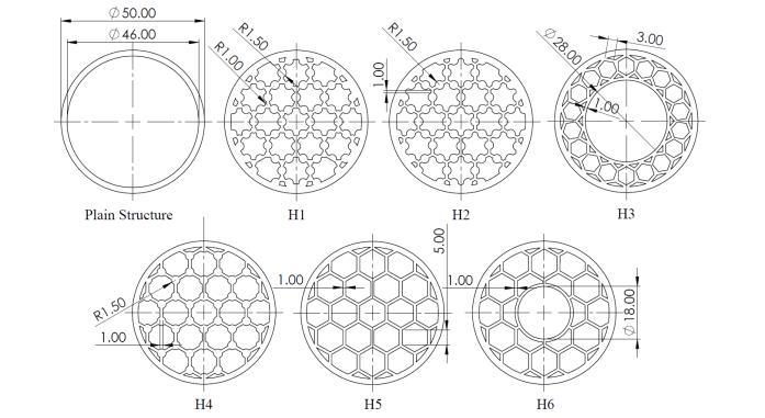
Tensile tests were performed to obtain the tensile strength and to understand the failure criterion. Through visualinspection,itisevidentthatthetensilespecimenatthe gauge length was elongated and the polymer chains were elongated along the tensile load direction. The elongation withanincreaseinthetensilestrengthwascontinueduntilit reached toultimate tensile strength of45.5 MPa, and then neck growth was stopped. Then, the elongation was continued at a slower rate with decreased strain until the crackpropagatedwasendedupwithaspecimenbreak.From theresultsshowninFigure2,thedisplacementinitiallyinthe elasticregionincreasedataveryslowratewithanincrease inthetensilestrength.Whenthetensilestrengthdroppeda bittoMPaandconstantincreasewasnoticedinthenecking region.Themaximumrecordedstrainwas18mm.
Thefabricatedstructuresweresubjectedtomechanical characterization tests to understand the behaviors under tensile and compression loading. The tensile tests were performedaccordingtotheASTMD-638Type-Vstandards and ASTM 690 standards for compression testing at room temperature. For repeatability, three specimens for each configuration of structures were tested and the average
However,the3dprintedlayersalongthedirection of the print tended to support and resist the specimen to failure.Fromtheresultsofthestress-strainplot,itisevident thatthespecimenshaveundergoneelongation,followedby neckingandthinning
The results represented in the figure, indicate the UTS was 45.5 MPa and the interlayer bonding was stronger
International Research Journal of Engineering and Technology (IRJET) e-ISSN: 2395-0056
Volume: 11 Issue: 05 | May 2024 www.irjet.net p-ISSN: 2395-0072
among 3D printed specimens. Likely, the 3D printing parameters chosen had given the better output which concluded the parameters followed will get appropriate resultsandthus,asimilarprocedurehadbeenfollowedin3D printingallthehoneycombconfigurations.
The compression tests for plane cylindrical and all honeycomb configurations were performed at a constant strain rate and their results were presented. The results includetheforcevsdisplacementplotsobtainedunderthe axialcompressionloadingat2mm/minshowninFigure3 Further,theloadabsorbedanddisplacementsobtainedwere plottedindividuallyforeachspecimenrepresentedinFigure 4andFigure5
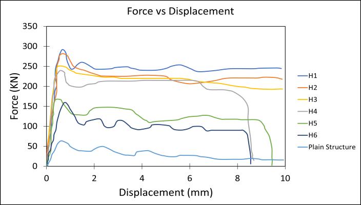
Fig -3:ForcevsDisplacementforallstructures
Initially, the plane cylindrical structure was subjected to the axial load on its top surface and the maximum load obtained was 63.38 KN with a maximum displacement of 10 mm. The top surface subjected to load startedtoabsorbtheloaduntilitgraduallyreached63KN, thenitstartedto exhibitnonlinearityandendedupwitha buckle on the loaded end resulting the fluctuations in the forcevsdisplacementplots Duringbuckling,aninstability compressionwasobservedduetothesuddenphasechanges betweenthehardandsoftphaseswithinthestructureofthe material.
The H1 structure was able to withstand the maximum load of 291.55 KN compared to all honeycomb structural configurationsandobtainedadisplacementof9.78mm.The H1 structureexhibitedhigher load bearingcapacity which was78.26%higherthantheconventionalplanecylindrical structure.Duetoitshigherrelativedensityandcylindrical cells,withminimalsharpedgesresultedinthereductionof stressconcentrationandproperloaddistributionthroughout the structure. The Samples were buckled at the top end wheretheaxialloadwasapplied.Afterthemaximumload wasattained,thestructurestartedtobucklealongtheedges ofthecylindricalwalls.
SimilartostructureH1, thesame buckling pattern was obtainedatthecontactofcylindricalwallstotheunitcells andalsoatcontactsamongtheunitcells.Duetotheabsence of cylindrical cells at the edges, the resistance to load was reducedwhencomparedtostructureH1.However,structure H2with77.9%higherload-bearingcapacitythantheplane cylindricalstructureandendedupwithdensificationatthe maximumdisplacementof9.87mm.
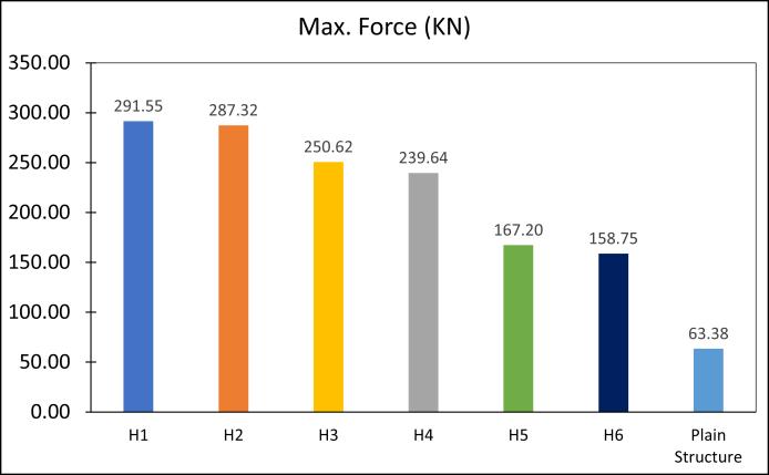
Fig -4:MaximumForceinKNobtainedunderaxial compressiontestforallstructures
Structure H4 exhibited a similar way of buckling to H2 wherethecrackswerepropagatedfromtheverticesofthe unitcellstoedgesandcontactsbetweentheunitcellstothe outercylindricalwallofthestructure.However,thestructure H4exhibitedlowerload-bearingcapacitywhencomparedto H1,H2,andH3and73.55%higherthantheplanecylindrical structure.
The structure H3 has exhibited better resistance to appliedloadwhencomparedtoH4,H5,andH6structures. UnliketheH1andH2structuresH3consistsofahollowinner wallanditscellsaredistributedinacirculararray. Duetoits uniquecelldistribution,itsrelativedensitywashigherwhich helpsinresistingthesuddencollapseofstructureunderaxial loading.Eventhoughtheunitcellcollapsingwasinitiatedat the center of the structure on the inner wall to unit cell contact it propagated eventually ending up with buckling. However,comparedtotheplanecylindricalstructureitwas abletoexhibit74.71%higherload-bearingcapacity.
International Research Journal of Engineering and Technology (IRJET) e-ISSN: 2395-0056
Volume: 11 Issue: 05 | May 2024 www.irjet.net p-ISSN: 2395-0072
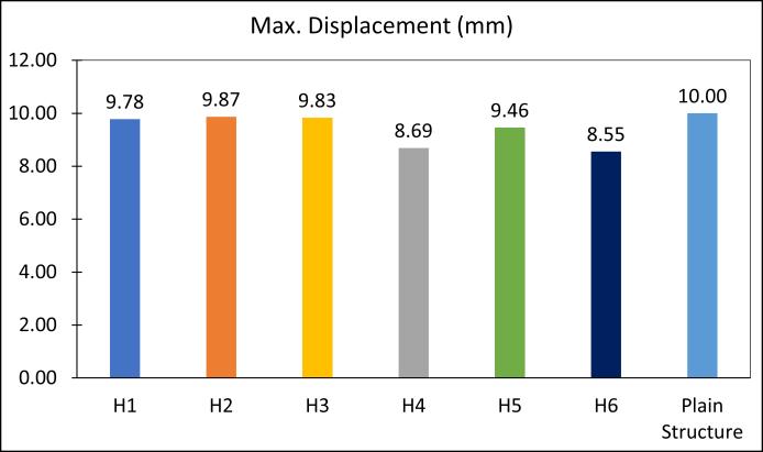
Fig -4:MaximumDisplacementinmmobtainedunder axialcompressiontestforallstructures
ThestructureH5consistsofevenlydistributedhoneycomb cellswhichledtoexhibitingbetterload-bearingcapability, which was 62% higher than the conventional plane cylindrical structure. The structure was buckled along the contacts of unit cells with the inner walls of the outer cylindricalstructure.Themaximumloadobtainedfromthe resultswas167.20KN.
The structure H6 exhibited a 60% higher load-bearing capacity than the conventional plane cylindrical structure. Thecollapseoftheunitcellsinitiatedattheinnerwallsand propagatedtotheunitcellsandeventuallyendedupwiththe bucklingfailureat158.75KN
Inthisstudy,themechanicalcharacterizationand deformation behavior of the plane cylindrical, H1, H2, H3, H4, H5, and H6 hexagonal structures under axial compression load were investigated The hexagonal structuresweredesignedaftervascularplanthexagonalcell distribution, withfewadditional changesaccording tothe literature. These structures were 3D Printed through the FDM technique and subjected to axial compression loads underASTMstandardsatroomtemperature
Fromtheresults,itwasobservedthatthechangesin structuraltopologyatagraduallevelwereinfluencingthe mechanical performance of honeycomb structures. In addition,thecircularunitcellswereabletoreducethestress concentrationswheninculcatedatedges,vertices,andjoints between unit cells All structures showed distinct deformationbehaviorsbasedontheirrelativedensityand geometrical stiffness when subjected to axial loading. However, they exhibited similar failures beginning with geometricalnonlinearityduringloadingatthetopsurfaceof each structure resulting the fluctuations in force vs displacementplots.Then break of contactoftheunitcells withwallsandcontactinbetweenunitcellsgraduallystarts collapsingwhenenteredintotosofteningphaseandoffers resistancewhentheyareinthehardeningphase.Ultimately,
theirregularpatternintheforcevsdisplacementplotwas continueduntilthestructuresendedupbuckling.However, whencomparedtoplainconventionalcylindricalstructure theH1structureshowed78.26%,theH2structure77.9%, theH3structure74.71%,theH4structure73.55%,theH5 structure 62%, and the H6 structure 60% increased load bearingcapacities
[1] Gao, Nansha, Hong Hou, and Jiu Hui %J International Journal of Modern Physics B Wu. 2018. "A composite and deformable honeycomb acoustic metamaterial.", 32(20):1850204.
[2] Almutairi,MohamedM,MohamedOsman,andIskander %JJournalofEnergyResourcesTechnologyTlili.2018. "Thermalbehaviorofauxetichoneycombstructure:an experimental and modeling investigation." 140 (12):122904.
[3] Bitzer, Tom. 1997. "Honeycomb core." In Honeycomb Technology: Materials, Design, Manufacturing, ApplicationsandTesting,10-42.Springer.
[4] Xiang, Jinwu, Jianxun %J Materials Science Du, and Engineering:A.2017."Energyabsorptioncharacteristics ofbio-inspiredhoneycombstructureunderaxialimpact loading." 696:283-289.
[5] Chen, BC, M Zou, GM Liu, JF Song, and HX %J InternationalJournalofImpactEngineeringWang.2018. "Experimental study on energy absorption of bionic tubes inspired by bamboo structures under axial crushing." 115:48-57.
[6] Smeets, Bart JR, Edward M Fagan, Kelly Matthews, RobertTelford,BrendanRMurray,LeonidPavlov,Bryan Weafer,PatrickMeier,andJamie%JCompositesPartB: EngineeringGoggins.2021."Structuraltestingofashear webattachmentpointonacompositelatticecylinderfor aerospaceapplications." 212:108691.
[7] Sun, Guangyong, Xintao Huo, Hongxu Wang, Paul J Hazell,andQing%JCompositesPartB:EngineeringLi. 2021."Onthestructuralparametersofhoneycomb-core sandwich panels against low-velocity impact." 216:108881.
[8] San Ha, Ngoc, and Guoxing %J Composites Part B: EngineeringLu.2020."Areviewofrecentresearchon bio-inspired structures and materials for energy absorptionapplications." 181:107496.
[9] McKittrick,J,P-YChen,LTombolato,EENovitskaya,MW Trim,GAHirata,EAOlevsky,MFHorstemeyer,MA%J Materials Science Meyers, and Engineering: C. 2010.
International Research Journal of Engineering and Technology (IRJET) e-ISSN: 2395-0056
Volume: 11 Issue: 05 | May 2024 www.irjet.net p-ISSN: 2395-0072
"Energy absorbent natural materials and bioinspired designstrategies:areview." 30(3):331-342.
[10] Zhang,Jianjun,GuoxingLu,andZhong%JComposites PartB:EngineeringYou.2020."Largedeformationand energy absorption of additively manufactured auxetic materialsandstructures:Areview." 201:108340.
[11] Zahran,MS,PuXue,andMS%JInternationalJournalof CrashworthinessEsa.2017."Novelapproachfordesign of3D-multi-cellthin-walledcirculartubetoimprovethe energy absorption characteristics under axial impact loading." 22(3):294-306.
[12] Xu,Mengchuan,ZiranXu,ZhongZhang,HongshuaiLei, YingchunBai,andDaining%JInternational Journal of MechanicalSciencesFang.2019."Mechanicalproperties and energy absorption capabilityofAuxHexstructure under in-plane compression: Theoretical and experimentalstudies." 159:43-57.
[13] Alhat, Sumeet M, and Manisha H Yadav. 2020. "Mechanical and Electrical Behavior of Polyethylene TerephthalateGlycol(PETG)ReinforcedwithMultiwall CarbonNanotubes(MWCNT)byusingFusedDeposition Modeling3DPrinting."
[14] Özen, Arda, Bilen Emek Abali, Christina Völlmecke, Jonathan Gerstel, and Dietmar %J Applied Composite Materials Auhl. 2021. "Exploring the role of manufacturing parameters on microstructure and mechanical properties in fused deposition modeling (FDM)usingPETG." 28(6):1799-1828.
[15] Solomon, I John, P Sevvel, and JJMTP %J Materials Today: Proceedings Gunasekaran. 2021. "A review on thevariousprocessing parameters in FDM." 37:509514.
[16] Sankineni, Rakesh, and Y %J Proceedings of the InstitutionofMechanicalEngineersRaviKumar,PartC: Journal of Mechanical Engineering Science. 2022. "Evaluation of energy absorption capabilities and mechanical properties in FDM printed PLA TPMS structures." 236(7):3558-3577.
[17] Zurnacı,Erman,andHaydarKadir%JGaziMühendislik Bilimleri Dergisi Özdemir. 2023. "Investigation of the compressivestrength,energyabsorptionpropertiesand deformationmodesofthereinforcedcorecellproduced bytheFDMmethod." 9(1):1-11.
2024, IRJET | Impact Factor value: 8.226 | ISO 9001:2008