
International Research Journal of Engineering and Technology (IRJET) e-ISSN: 2395-0056
Volume: 11 Issue: 05 | May 2024 www.irjet.net p-ISSN: 2395-0072
International Research Journal of Engineering and Technology (IRJET) e-ISSN: 2395-0056
Volume: 11 Issue: 05 | May 2024 www.irjet.net p-ISSN: 2395-0072
Nishma TH1 , Dr.Chethan K2
1 P.G Student, Department of Civil Engineering, U.V.C.E, Bangalore University, Bengaluru
2 Associate Professor, Department of Civil Engineering, U.V.C.E, Bangalore University, Bengaluru
Abstract - For reinforced concrete (RC) buildings to maintain their structural integrity and the safety of its occupants during earthquakes, seismic performance assessment is essential. The first step in the research is to create ETABS models that faithfully capture the dynamic behaviour ofreinforcedconcrete buildings. Subsequently, the LRB and HDRB isolators are reviewed, chosen, and designed. Time history loads are applied to determine the models' reaction. Assessing the effectiveness of isolators in reducing earthquake-induced damages by contrasting the exceedance probabilitiesoffixedandbase isolatedstructures.Thestudy's findings offer crucial data for assessing the structure's anticipated seismic performance and creating focused mitigation plans. Various preceding earthquakes are considered and compared to obtain the better performance. TotalsevenearthquakeswithreferencetoIS1893:2016(part 1) are taken. With infillthat is with equivalent diagonalstrut and without infill having two types of storey- low rise and mediumrisewithbasicbeam-column-slabstructuresareused in this thesis
Key Words: Base isolation, Lead rubber bearing, High dampingrubberbearing, equivalent diagonal strut
1.INTRODUCTION
Inearthquake-proneregions,theimportanceofearthquakeresistantbuildingscannotbeoverstated.Theyareacritical component of disaster preparedness and risk reduction, helpingtoprotectlives,property,andtheoverallwell-being of communities. Building structures that can withstand seismic forces is a proactive and responsible approach to managingtherisksassociatedwithearthquakes.Theground thatunderpinseverybuildingshiftduringearthquakes.Asa result,thebuilding'sbasemovesalongwithit.However,the buildingwillmakeanefforttoresistthismotionbecauseof itsinertia.Thebuildinggetsdistortedasa result,andthis distortionincreaseswiththebuilding'sheight.
Baseisolationisaseismic-resistantdesignstrategythat seeks to break the direct mechanical link between a building'ssuperstructureanditsfoundation.Withthearrival of multilayer elastomeric bearings, which are created by vulcanizingrubbersheetstothinsteelreinforcingplates,the ideaofseismicisolationhasbecomearealitythroughoutthe
past20years.Theseareextremelyrigidbearingsalthough they are highly adaptable, they can support the building's verticalweightintheverticaldirectionhorizontally,allowing thestructuretoshiftlaterallyintheeventofextremeground motion. their creation represented a growth in the applicationofelastomericbridgebearingsandbearingsfor thebuilding'sisolationfromvibration.Theconceptofbase isolationisnowwidelyacceptedinearthquake-proneregions oftheworldforprotectingimportantstructuresfromstrong ground motion; there are currently many examples in the UnitedStatesandJapan.Othersystemsthataremodifications oftheslidingapproachhavebeendevelopedinrecentyears.
AimstoperformFiniteElementAnalysis(FEA)forfixed baseandbaseisolationfor3DRCbuildingforSeismicloads. Design and apply base isolators at the supports 3D RC Buildings are done. Carry out Finite elemental analysis whichinvolvesmodalanalysisandTimehistoryanalysisand comparethefixedbaseresultswithbaseisolatedmodelsfor differentstoreyheight.
RCframedstructurewithandwithoutinfillisconsidered,two typesofbuildingintermsofheightisbeingconsidered,low rise(5Floors)andmediumrise(13Floors).Allthemodels have5baysof8mwidthinbothperpendiculardirectionsin thehorizontalplane Timehistoryanalysisiscarriedoutin ETABS software. The structural material is assumed to be isotropicandhomogeneous
Variousloadsareappliedtothestructuralmodels.PartIof theIndianStandardCodeofPracticefortheStructuralSafety ofBuildings,IS875-1987,specifiestheloadsthatweretaken intoaccountforthestudy.Theloadstakenintoaccountin thisworkare
i.DeadLoaddesignatedas“DL”
ii.LiveLoaddesignatedas“LL”
iii.EarthquakeLoaddesignatedas“EQX”,EQY”&“TH”
International Research Journal of Engineering and Technology (IRJET) e-ISSN: 2395-0056
Volume: 11 Issue: 05 | May 2024 www.irjet.net p-ISSN: 2395-0072
MODEL G+4 (low rise) G+12 (medium rise)
Typeofstructure SMRF SMRF
Gradeofconcrete M40(40 N/mm2) M40(40 N/mm2)
Gradeof Reinforcingsteel
Fe500(fy= 500N/mm2)
Fe500(fy= 500N/mm2)
Numberofstories G+4 G+12
Columnsize 600X600mm
X800mm
MainBeamsize 450X600mm 450X600mm
SecondaryBeam size
300X600mm 300X600mm
DeadLoadonFloor 3.0kN/m2 3.0kN/m2
LiveLoadonFloor 3.0kN/m2 3.0kN/m2 Importancefactor 1.5 1.5 Zone
‘Z’
‘R’ 5 5
2.1 Models
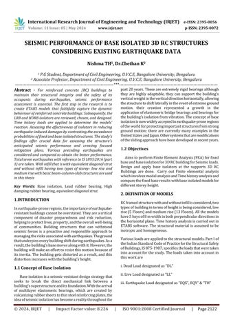
Thefloors/slabsaremodeledasmembraneelementsforthe Column beam slab system. The floor slab is considered as rigid diaphragm. The typical plan and sectional view of 5floor and 13-floor buildings are shown in figure 1. The buildingdetailsandmaterialpropertiesaregiveninTable-1 above.
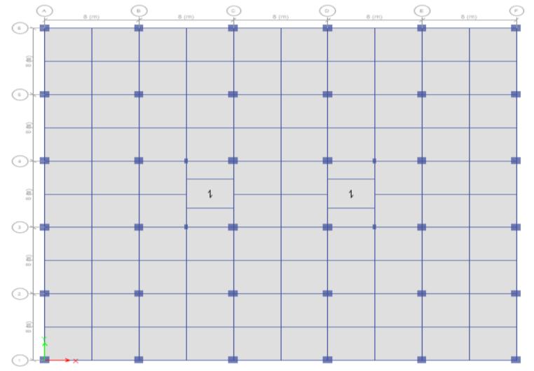
Fig -1:Planofallthemodels
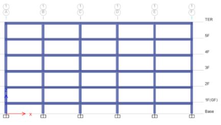
Fig -2:Elevationof5floorbuilding
Fig -3:Elevationof13floorbuilding
3. METHODOLOGY
TheloadingstandardsIS875(PartI&PartII):1987andthe Indian Standard Code of Practice for Structural Safety of Buildings have been used as the foundation for the calculation of gravity loads, including dead and live loads, thatareappliedtotheframes.Theself-weightofstructural and non-structural components, such as wall load and parapetload,isknownasthedeadload.
A. Deadloads
Floor Finish + Partition load =1.5 kN/m2+1.5 kN/m2 = 3.0 kN/m2 Wall Load +plaster on two sides
(wallloadsareconsideredontheperipheralbeams andatstaircaselobby)
0.2x(3.5–0.45)X17.65+ 2*.02*3.35*20.4= 13.5 kN/m
Allfloors:3kN/m2
C. SeismicLoads
In addition to gravity loads, earthquake loads are consideredfortheanalysisofthestructurelocated
International Research Journal of Engineering and Technology (IRJET) e-ISSN: 2395-0056
Volume: 11 Issue: 05 | May 2024 www.irjet.net p-ISSN: 2395-0072
inseismiczone-v,asperIS:1893-2016(Part-I).The seismic details of the building are listed below in Table-2.
Table-2:Seismicparameters(IS:1893-2016,Part-I)
For the seismic loads, mass source is to be defined as per codalprovisions.Astheimposedloadforpresentbuildingis 3kN/m2(<=3kN/m2),asperIS:1893-PartI,Table10,25% of the imposed load is considered for seismic weight calculationalongwithtotaldeadloadsapplied.Ifimposed load exceeds 3kN/m2, then 50% of such load plus all the deadloadsisconsideredforseismicweightcalculationThe detailed seismic analysis is carried out for the considered lowrise&mediumrisebuildingconsideringprimaryloads (dead,live&seismicloads)forallthemodels.
Itisanexaminationofthestructure'sdynamicresponseata certainpointintimewhenitsbaseisexposedtoaparticular groundmotionhistory.Attheproperplacesandtimesteps, thechosentimehistoryrecordingsareappliedtothefinite elementmodelasinputexcitations.Amultitudeofelements aretakenintoconsiderationduringtheintricateprocessof selectingtimehistorydatafortimehistoryanalysis.Usually, thedesignparametersandseismichazardassessmentsfor thearea inwhichthe structure issituatedare established initially.Next,seekandgatherasetofrepresentativeground motionrecordingsutilizinghistoricalrecords,probabilistic seismichazardevaluations,orexistingseismicordynamic datasources.
To guarantee that these records appropriately depict the structure's anticipated dynamic loading scenarios, they shouldhavecharacteristicssuchasspectralform,frequency content, amplitude, and length that match the design spectrum.Validationwithsyntheticdataorrecordedevents demonstratesitsapplicabilityandrelevanceforaccurately simulating the dynamic response of the structure being studied.FastNonlinearAnalysis(FNA)isusedinETABSto analysethetemporalhistory.Themodalanalysistechnique known as FNA can be applied to the static or dynamic assessment of structural systems that are linear or nonlinear.Duetoitscomputationallyefficientformulation,
FNA is frequently preferred over direct-integration applicationsintime-historyresearch.Analyticalmodelsused indynamic-nonlinearFNAapplicationsshouldgenerallybe linear-elastic, have a small number of preset nonlinear elements,Nonlinearlumpbehaviourwithinlinkobjects.
Thegroundmotionhasdynamiccharacteristics,whichare peakgroundacceleration(PGA),peakgroundvelocity(PGV), peak ground displacement (PGD), frequency content, and duration.Thesedynamiccharacteristicsplayapredominant roleinstudyingthebehaviorofRCbuildingsunderseismic loads. The structure stability depends on the structure's slenderness, as well as the ground motion amplitude, frequency,andduration.
Based on the frequency content, which is the ratio of PGA/PGVthegroundmotionrecordsareclassifiedintothree categories High-frequency content PGA/PGV > 1.2, Intermediate-frequency content 0.8< PGA/PGV< 1.2 and Low-frequency content PGA/PGV < 0.8. The time history dataselectedforthepresentanalysisisshowninTable3.
Table-3: Timehistorydataoftheselectedearthquakesfor carryingouttimehistoryanalysis.
The parameters chosen for the base isolated models are provided in Figures 2, 3, and Table 4, Table 5 for the LRB IsolatorandHDRBIsolator,respectively,whichareintended for the forces acquired from the Analysis of Fixed Base Modelsforthecurrentstudy.
International Research Journal of Engineering and Technology (IRJET) e-ISSN: 2395-0056
Volume: 11 Issue: 05 | May 2024 www.irjet.net p-ISSN: 2395-0072
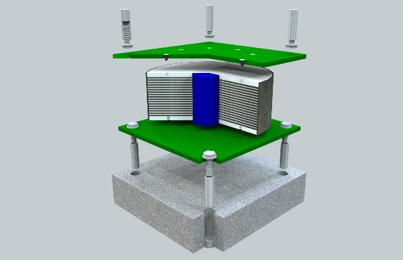
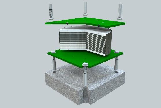
Table 4
Table 5
propertiesof13floorsbuilding
Thegravityloadssuchasdeadandliveloadscomingonthe frameshavebeencalculatedbasedonprovisionsgiveninthe Indian Standard Code of Practice for Structural Safety of Buildings,loadingstandardsIS875(PartI&PartII):1987. Thedeadloadconsistsofself-weightofstructuralandnonstructuralelementslikewallload,andparapetload.
Thefundamentalperiodisthedurationofthefirstvibrational mode.Theeffectsofstiffness(stifferbuildingshaveshorter naturalperiods),mass(heavierbuildingshavelongernatural periods),buildingheight(tallerbuildingshavelongernatural periods),crackedsections on RCframeanalysis(buildings with shorter natural periods are estimated using gross stiffness, while longer natural periods are estimated using effectivestiffness),andnaturalperiodondesignhorizontal seismicforcecoefficient(buildingswithshortertranslational natural periods attract higher design seismic force coefficient) are some of the factors that affect a building's natural period. Table 6 shows the modal time period obtainedforthefourtypesofframingsystemsfor5and13floorbuildings withfixed base andbase isolated withLRB andHDRBisolators.
International Research Journal of Engineering and Technology (IRJET) e-ISSN: 2395-0056
Volume: 11 Issue: 05 | May 2024 www.irjet.net p-ISSN: 2395-0072
The change in base shear seen with a fixed base and a base isolated using two different kinds of isolators is showninFigure5.
Table6
Modaltimeperiod
Thecomparisonofthemodaltimeperiodwithfixedbaseand base-isolatedbuildingswiththreetypesofisolatorsisshown inFigure4.Itcanbeobservedthatthepredominantperiodof thestructureislengthenedforthebase-isolatedbuildingsas expected.
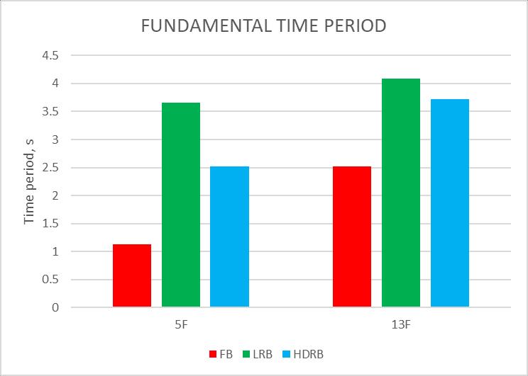
Fig4
Fundamentaltimeperiod
ItcanbeobservedfromFigure4andTable6thatwhen compared with the fixed base buildings of 5 floors the timeperiodincreasesby3.6and2.4timesforLRBand HDRBbuildingsrespectively.For13Floorsbuildingsthis increase is 1.66 and 1.56 times, overall time period increasesduetobaseisolation.
B. Base Shear
Buildings vibrate during an earthquake, inducing an inertiaforcewithinthestructure.Themajorityofdesign codesexpresstheneteffectofsuchrandomshakingasa design-equivalent static lateral force, which is how earthquake-inducedinertiaforcesarerepresented.The force that results from using seismic design codes is known as the design seismic base shear or the design seismic lateral force of the building. Seismic design standards offer a design response spectrum. The fundamentalquantityinforce-basedearthquake-resistant structuredesignisstillthisforce,whichisknownasthe SeismicDesignBaseShear(VB).Thisforceisdetermined by the seismic risk at the building location, which is indicated by the Seismic Zone Factor Z. The seismic coefficientmultipliedbythetotaloftheseismicmassesat various floor levels yields the seismic base shear (VB).
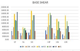
Fig5 BaseShear
ThevariationinbaseshearisshowninFigure5withfixed base and base-isolated building with LRB and HDRB isolators.Itcanbeobservedthatanaverageofabout80% to 90% reduction in the base shear is observed for the base-isolatedbuildingwhencomparedwiththefixedbase buildingsof5floors.Anaverageofabout50%reduction isalsoobservedin13floorsbuilding.
C. Maximum Storey Displacement
The deformation of the structurebrought about by the application of lateral forces is known as lateral displacement. Absolute values of the maximum roof storeydisplacementsalonglateraldirectionsareselected for the comparative research. At the isolator level, a significant amount of lateral displacement is seen for base-isolatedbuildings.Modelswithfixedbaseshaveno displacementatthebase.Thestoreydisplacementofthe isolatedmodelsisrepresentedinrelationtotheisolator displacement for comparison's sake, as the lateral displacement variation for base-isolated buildings is negligible at higher elevations. In contrast, the lateral displacementincreasedsignificantlyinthecaseoffixed base buildings. The variations in the peak roof displacements are compared against the fixed base buildingandbase-isolatedbuildingswithLRBandHDRB isolators for 5 floors and 13 floors and are shown in Figure6.
It can be observed that there is a reduction in roof displacementwithbothLRBandHDRBisolatorsforall thetimehistorycasesconsidered.
International Research Journal of Engineering and Technology (IRJET) e-ISSN: 2395-0056
Volume: 11 Issue: 05 | May 2024 www.irjet.net p-ISSN: 2395-0072
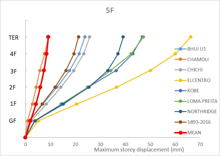
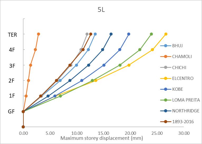
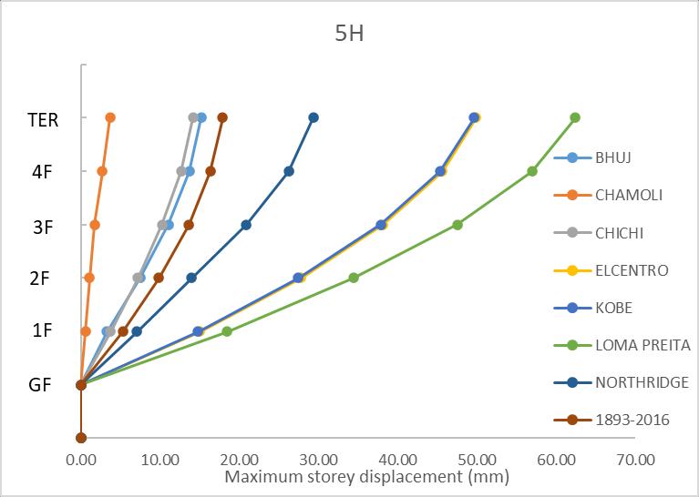
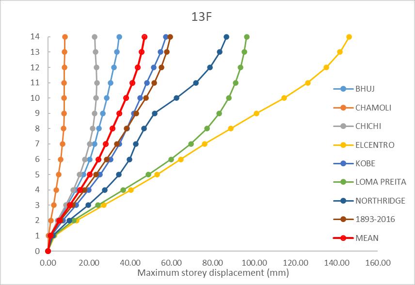
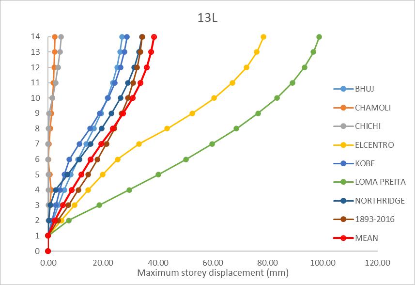
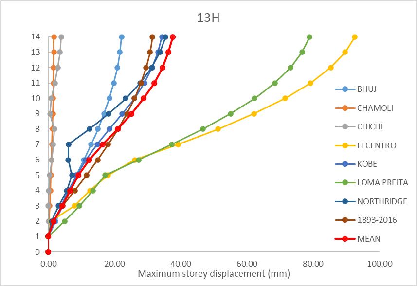
Fig6
MaximumstoreyDisplacement
8.
An attempt is made to investigate an RC monolithic buildingof5and13storeymodeledasathree-dimensional structureinETABSSoftwaretostudytheseismicresponse withbase-isolatedandfixedbaseconditionssituatedinall fourseismiczonesVwithsoiltypeI(hardsoil).
1. Lengtheningofthefundamentalperiodofthebase isolation system results in a reduction of the
International Research Journal of Engineering and Technology (IRJET) e-ISSN: 2395-0056
Volume: 11 Issue: 05 | May 2024 www.irjet.net p-ISSN: 2395-0072
maximumaccelerationandhencethereductionin earthquake-inducedforcesinthestructure.
2. FortheRCmonolithicbuildingwithabaseisolation system,thebaseshearwasreducedsignificantly.
3. Forisolatedbasemodelsthedisplacementbetween the ground floor level and roof level is very less compared with the displacement between the ground floor level and roof level of fixed base models.
TheresultsshowthattheBaseIsolationisveryeffective atlesseningtheseismicresponseofthestructure.
Barbat A. H. and Bozzo L. M. “Seismic analysis of baseisolatedbuildings”,Volume4,pages153–192, (1997)
Boomarine supplies. (n.d.). Retrieved from Bing images: https://www.boomarine.com/products/leadrubber-bearing
• ChengqingLiuandDengjiaFang.“SeismicFragility Analysis of Base Isolated Structure Subjected to Near-faultGroundMotions.”PeriodicaPolytechnica CivilEngineering,65(3),pp.768–783,2021
• Gandage,Shivani.,Salgado,Ryan.,andGuner,Serhan. (2019)“FFG:FragilityFunctionGenerator,”MacroEnabledExcelSpreadsheet,DepartmentofCiviland Environmental Engineering, The University of Toledo,Ohio,USA.
• Hossein Monfared, Ayoub Shirvani and Sunny Nwaubani. “Aninvestigationinto theseismic base isolationfrompracticalperspective”.International journal ofciviland structuralengineering,Volume 3,No3,2013
• Islam,A.B.M. S.,&Al-Kutti,W. A.(2018). Seismic response variation of multistory base-isolated buildings applying lead rubber bearings. Comput. Concr,21,495-504.
• RajeshReddyM.,Dr.SrujanaNandLingeshwaranN. “Effect of base isolationinmultistoried reinforced building”.InternationalJournalofCivilEngineering andTechnology(IJCIET),Volume8,Issue3,March 2017,pp.878–887ArticleID:IJCIET_08_03_088
• Usta P. “Investigation of a Base-Isolator System’s Effects on the Seismic Behavior of a Historical Structure”.Buildings2021,11,217.
• SarveshK.JainandShashiK.Thakkar,“Application ofbaseisolationforflexiblebuildings”,13thWorld ConferenceonEarthquakeEngineeringVancouver, B.C.,CanadaAugust1-6,2004PaperNo.1924.
• PatilS.J.and ReddyG.R..“StateOfArtReview-Base Isolation Systems For Structures”, International Journal of Emerging Technology and Advanced Engineering,Volume2,Issue7,July2012.
• Sajal Kanti Deb. “Seismic base isolation – An overview”,CurrentScience,Vol.87,NO.10,25Nov 2004.
• Scawthorn, C., & Chen, W. F. (Eds.). (2002). Earthquakeengineeringhandbook.CRCpress.
• SunitaTolaniandDr.AjaySharma.“Effectivenessof BaseIsolationTechniqueandInfluenceofIsolator Characteristics on Response of a Base Isolated Building”,AmericanJournalofEngineeringResearch (AJER) e-ISSN: 2320-0847, p-ISSN : 2320-0936, Volume-5,Issue-5,pp-198-209(2016)
• Sushil P.Lipte,Dr.V.R.RathiandDr.P.K.Kolase. “Seismic response control of RC building by using base isolation system”, International Journal of Management,TechnologyandEngineeringVolume 8,IssueIX,SEPTEMBER/2018,ISSNNO:2249-745.