
International Research Journal of Engineering and Technology (IRJET) e-ISSN: 2395-0056
Volume: 11 Issue: 05 | May 2024 www.irjet.net p-ISSN: 2395-0072
International Research Journal of Engineering and Technology (IRJET) e-ISSN: 2395-0056
Volume: 11 Issue: 05 | May 2024 www.irjet.net p-ISSN: 2395-0072
Ar. Monisha
1 ,
Ar.Fathima taskeen
2 ,
Ar.Indrapriya
3
1Post Graduate student, Faculty of architecture, Dr. MGR University, Tamil nadu, India
2Deputy HOD, Faculty of Architecture, Dr. MGR University, Tamil nadu, India
3Additional HOD, Faculty of Architecture, Dr. MGR University, Tamil nadu, India
Abstract - The construction structure resembles the skeletal framework of a human body, serving as the essential support upon which the entire building relies. Every component within construction contributes to this support, varying in their degree of importance as they uphold both themselves and adjacent elements. The present studywascarriedouttoanalyzethestructuralperformance of the G+10 story framed structure subjected to seismic loading of Zone 3 using ETABS software. Four similar models having the Difference plan configuration is prepared. The comparison of conventional reinforced concrete structure with Mivan Technology, bracing system, Diagrid structure, steel plate shear wall system is done and the result obtained is compared in terms of the structural performance of the following parameters-maximum story displacement,storydrift,storyDriftandstorydisplacement.
Key Words: ETABS, Storey Drift, Storey Displacement, Time and cost
1. INTRODUCTION
Worldwide, there's a significant demand for constructing high-rise buildings due to the expanding population. Designing engineering structures to be earthquakeresistant is crucial for mitigating potential damage from future seismic events. The seismic design of structures relies on ground motion specifications derived from past earthquake data. Thus, creating earthquake-resistant designs tailored to seismic frequencies is paramount for minimizingdamage.However,earthquakeforcesvaryand are unpredictable. Hence, software tools are essential for analysing structures under various seismic forces. So the significance of effectively designing and constructing earthquake-resistant structures cannot be overstated. To address this, ETABS offers comprehensive static and dynamic analysis capabilities, accommodating a diverse arrayofgravity,thermal,andlateralloads.
2. OBJECTIVE
The study involves a comparison of four technologies: concrete structures, bracing systems, diagrid structures, and steel plate concrete composite shear wall structures.
Theprimaryaimistoidentifysuitablestructuralformsfor effectivelyresistingseismicloadsinhigh-rise buildings,as well as to compare the performance of load and drift in seismiczonesandassessthecostandtimeimplicationsof advancedstructuralforms.
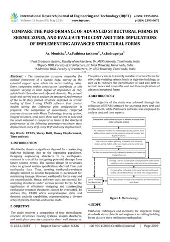
The objective of the study was achieved through the utilizationofETABSsoftwareforanalysingstorydriftand displacement, whilePrimavera software was employed to analysecostandtimeaspects.
Figure 1: Methodology
4. SCOPE
Validating techniques and mediums for improved living standardsaidsarchitectsandengineersincraftingbuilding formsthataremoreresilienttoearthquakes.
International Research Journal of Engineering and Technology (IRJET) e-ISSN: 2395-0056
Volume: 11 Issue: 05 | May 2024 www.irjet.net p-ISSN: 2395-0072
This study exclusively compared only four technologies based on their performance in drift and displacement within seismic zones, as well as their associated time and costfactorsduringconstruction.
6.1 LITERATURE STUDY -BRACING
The review of the journal paper involves a comparison of steel-bracedandun-bracedstructuresduringthecollapse, Bracing systems are highly effective in significantly reducing the deformations of structural members. Therefore, using bracing systems for seismic retrofitting canalsohelppreventprogressivecollapse ( Bikram Shah and Feng Xu, 2019 ).
6.2 LITERATURE STUDY -DIAGRID
Thereviewofthejournalpaperinvolvesa comparison of DIAGRID and TUBE structures in terms of displacement, Diagonal members in Diagrid structural systems can supportbothgravitiesloadsandlateralforcesduetotheir triangulated configuration. Diagrid structures are more effective at minimizing shear deformation because they handle lateral shear through the axial action of diagonal members (Mohsen Rostami, Fatemeh Gorji Sinaki, Abdolreza S. Moghadam, 2016 ).
6.3 LITERATURE STUDY - STEEL-CONCRETE
COMPOSITE SHEAR WALL
The review of the journal paper involves a comparison of braced frame structure and the SPSW system, An SPSW steelbuildingismoreeffectivethanabracedsteelbuilding intermsofstory driftand story displacement.BothSPSW steel buildings and braced steel buildings are more effective at reducing responses when they are positioned at the center rather than at the edge ( Dr. C Prabha and Mahima Mani K M,2022 ).
6.4 LITERATURE STUDY – MIVAN TECHNOLOGY
The review of the journal paper involves a comparison of the seismic performance of the mivan structure and conventionalstructure,thedisplacementofaconventional structural system is 26% greater than that of a Mivan structural system. Additionally, the Mivan structural systemhasanaverageof32%lessstorydriftcomparedto a conventional structural system ( M. Walvekar and Hemant L. Sonawadekar,2017 ).
7.1
In 1998, a construction project was completed, incorporatinganinnovativeintegratedX-bracingsystemin a 10-story high-rise office building spanning an area of 20,260 square meters. The height of the building is about 40 meters. This pioneering design features a repetitive X steelbracingsystemonthebuilding'sexterior,witheachXbracing unit measuring about 4 meters by 8 meters, intricately connected to the edge beams. The primary function of this structural element is to enhance the building's stability, particularly during wind and seismic events such as earthquakes. Bylimiting lateral movement, the X-bracing system significantly reduces the risk of damagetoboththestructuralcomponentsandtheexterior cladding,ensuringthebuilding'sresilienceandsafety.
In terms of cost and time analysis compared to conventional structures, the cost of the X-bracing system increases by about 7% while the time required for construction increases by about 4% when compared to conventionalstructures.
In 2024, a construction project was completed, incorporating the DIAGRID system in a 14-story high-rise office building spanning an area of 15,246 square meters. The height of the building is about 56 meters. The entire buildingisconstructedwithsteel,using316stainlesssteel for the DIAGRID structure. The DIAGRID structure is connected with pin joints to the steel edge beam of the building. The base size of the DIAGRID structure is about 900 mm of steel, which gradually reduces as the height increases. At the top, the DIAGRID structure is about 250 mm thick, which effectively minimizes shear deformation by carrying lateral shear through the axial action of the diagonalmembers.
In terms of cost and time analysis compared to conventional structures, the cost of the DIAGRID system increases by about 42% while the time required for construction decreases by about 52% when compared to conventionalstructures.
In 2024, a construction project was completed, incorporating the STEEL-CONCRETE COMPOSITE SHEAR WALL system in a 14-story high-rise office building spanning an area of 15,246 square meters. The height of the building is about 56 meters. The entire building is constructed with steel. The steel plate shear wall system ortubesystemisusedwitha4mmthicknessofsteelplate and M20 grade of concrete. The beams are connected to
International Research Journal of Engineering and Technology (IRJET) e-ISSN: 2395-0056
Volume: 11 Issue: 05 | May 2024 www.irjet.net p-ISSN: 2395-0072
the steel plate of the core, and the beam is connected to the outer edge beam and outer columns of the structure whichleadsto resistlateral loads(wind, seismic, impact). The building is designed to act like a hollow cylinder cantileveredperpendiculartotheground.
In terms of cost and time analysis compared to conventionalstructures,thecostofthe STEEL-CONCRETE COMPOSITESHEARWALLsystemincreasesbyabout37% while the time required for construction decreases by about66%whencomparedtoconventionalstructures.
In 2020, a construction project was completed, incorporating Mivan technology in a 16-story high-rise residential building spanningan area of 3,227,328 square feet. The height of the building is 58 meters. The entire building is constructed with a concrete structure. The walls have a thickness of 200mm and 150mm, while the slabshaveathicknessof150mm.Theshearwallstructure providesmoreseismicresistanceand durability,ensuring maximumsafetyduringearthquakes.
In terms of cost and time analysis compared to conventional structures, the cost of MIVAN TECHNOLOGY decreases by about 20% while the time required for construction decreases by about 48% when compared to conventionalstructures.
8.1
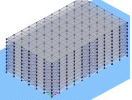
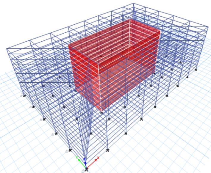
The selected site for the office is a high-rise building covering approximately 950,000 square meters, with a height of 10 stories. The floor plan measures about 100 meters by 60 meters. Conventional construction methods were used. The building specifications include a story heightof4meters,slabthicknessof200mm,wallthickness ranging from 75mm to 200mm, column dimensions of 1 meter by 1 meter, and a beam depth of approximately 800mm. The site is located in seismic zone III, with mediumsoilconditions.
TheanalysisisconductedusingETABsoftwaretoanalyze thedriftanddisplacementofbuildingsinvarious technologies.Thefourtechnologiesarenamedas:
Model1-Bracingsystem
Model2-Diagridsystem
Model3-Steel-ConcreteCompositeShearWallSystem
Model4-Mivantechnology(Shearwallsystem)
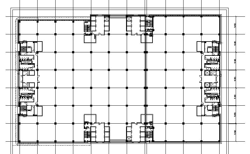
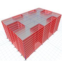
The proposed site incorporates an X-bracing system with specifications similar to conventional methods. The exterior structure utilizes steel X-bracing. The design includes a slab thickness of 200mm, wall thickness of 200mm, column dimensions of 1 meter by 1 meter, and a beamdepthofapproximately800mm.
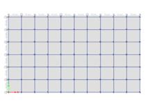
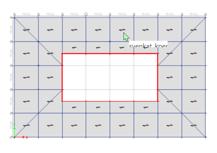
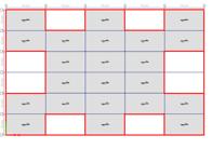
Figure 3: Model1-plan
International Research Journal of Engineering and Technology (IRJET) e-ISSN: 2395-0056
Volume: 11 Issue: 05 | May 2024 www.irjet.net p-ISSN: 2395-0072
8.2.2 Specification – Model 2
The Diagrid system is integrated into the proposed site, with specifications including a slab thickness of 200mm, wall thicknesses of 200mm and 75mm, and a beam depth of approximately 1000mm. The entire building is constructedusingasteelstructure.
8.2.3 Specification – Model 3
Theproposedsiteincorporatesasteel-concretecomposite shear wall system. The specifications include a slab thickness of 200mm, wall thicknesses of 200mm and 75mm,andabeamdepthofapproximately1000mm.
8.2.3 Specification – Model 3
Theproposedsiteincorporatesasteel-concretecomposite shear wall system. The specifications include a slab thickness of 150mm, wall thicknesses of 200mm and 75mm,andabeamdepthofapproximately1200mm.
International Research Journal of Engineering and Technology (IRJET) e-ISSN: 2395-0056
Volume: 11 Issue: 05 | May 2024 www.irjet.net p-ISSN: 2395-0072
RESULT: 9.1 SEISMIC ANALYSIS RESULTS
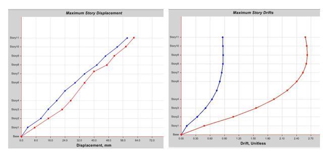
Figure 11: Model1-Drift&Displacement
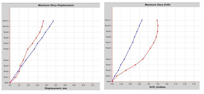
Figure 12: Model2-Drift&Displacement
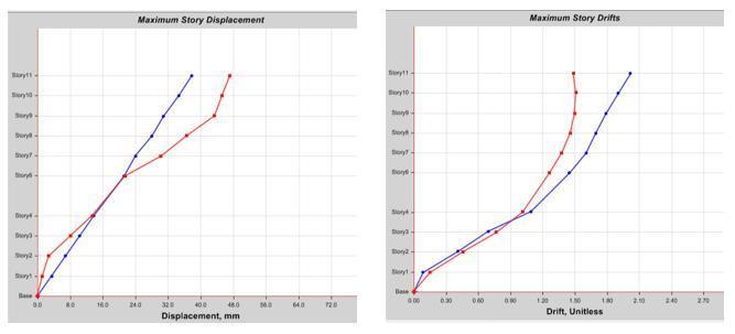
Figure 13: Model3-Drift&Displacement
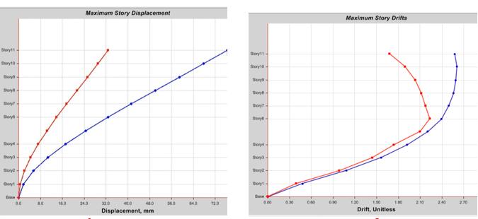
Figure 14: Model4-Drift&Displacement
In Model 1, the seismic analysis results indicate that the maximumdisplacementisapproximately49.5mmintheX direction and 52.2mm in the Y direction. The maximum driftis2.60intheXdirectionand0.88intheYdirection.
In Model 2 , the seismic analysis results indicate that the maximumdisplacementisapproximately28.5mmintheX direction and 38.2mm in the Y direction. The maximum driftis1.50intheXdirectionand0.93 intheYdirection.
In Model 3, the seismic analysis results indicate that the maximumdisplacementisapproximately47.0mmintheX direction and 30.1mm in the Y direction. The maximum driftis1.50intheXdirectionand1.66intheYdirection.
International Research Journal of Engineering and Technology (IRJET) e-ISSN: 2395-0056
Volume: 11 Issue: 05 | May 2024 www.irjet.net p-ISSN: 2395-0072
In Model 1, The cost of a bracing system structure is approximately 11% higher than that of a conventional structure, and the duration is also approximately 11% longer.
In Model 2, The cost of a diagrid structure is approximately 30% higher than that of a conventional structure,whilethedurationisreducedbyapproximately 33%.
In Model 3, The cost of a Concrete-Filled Composite Plate ShearWallSystemisapproximately27%higherthanthat of a conventional structure, while the duration is reduced byapproximately40%.
In Model 4, The Mivan technology saves approximately 13% in cost and reduces the duration by approximately 36%comparedtoconventionalmethods.
9. CONCLUSION:
The four technologies are more effective in seismic zones than conventional structures. Among them, the most effectiveinseismiczonesisthediagridstructure,followed by the steel-concrete composite shear wall system, the bracing system, and mivan technology. In terms of time and cost efficiency compared to conventional methods, mivan technology is the most effective, followed by the bracing system, the steel-concrete composite shear wall system,andfinally,thediagridstructure.
10. RECOMMENDATION:
In India, high-rise buildings, especially residential ones, arethemostaffectedinseismiczones.Thesebuildingsare more vulnerable than mid-rise structures. Therefore, residential buildings can incorporate a combination of mivan and bracing systems for better seismic performance.
The choice of technology depends on the height of the building. For example, concrete-filled composite shear wallscanbeusedforbuildingswithmorethan15floors.
Ifadynamicformofthebuildingistobeconstructed,the preferredtechnologyisthediagridstructure,asitcan withstandthedynamicformofthebuilding.
11. REFERENCE:
[1]https://www.academia.edu/76650976/Effects_of_Stee l_Bracings_in_the_Progressive_Collapse_Resistance_of_Rei nforced_Concrete_Building?sm=b
[2]https://www.academia.edu/43043729/Comparison_of _Braced_Steel_Building_with_Steel_Plate_Shear_Wall?sm=b