
Volume: 11 Issue: 05 | May 2024 www.irjet.net p-ISSN:2395-0072
Volume: 11 Issue: 05 | May 2024 www.irjet.net p-ISSN:2395-0072
Thangavelu EswaryDevi1 , Abdul Latheef Vahidha Banu2 , Ravindran Mugilvannan3
1,2,3Department of Civil Engineering, Meenakshi Sundararajan Engineering College, Kodambakkam, Chennai, Tamil Nadu, India-600024.
Abstract - The design of construction projects involve several stakeholders and inter-disciplinary data which include architectural, structural, plumbing and electrical aspects making the process highly complex. Numerous clashes may arise between the building elements attributed to the design demands of different disciplines which must be identified at an early design stage to avoid the risk of project delays and financial overburden. In General, majority of the clashes were identified during project execution which delayed the projects and involved schedule and cost implications. Recently, with the extensive application of Building Information Modeling (BIM), the clash detection has become easier, faster and utmost accurate reducing the project time and saving on contract value due to early clash detection. sAmong the clash detection software available in the Architecture, Engineering and Construction (AEC) industry viz., Autodesk Navisworks Manage was the most efficient BIM based software In this study, Autodesk Revit was used to create 3D model of a G+3 residential building which integrated Architectural, Structural, Electrical and Plumbing models. After model completion in Revit, the detailed 3D model was exported to Navisworks and Clash detection was carried out. Around six interdisciplinary model combinations were used and 251 hard clashes were identified with a significant portion arising between the architectural and structural models The detected clashes were resolved using Revit software. The clash detection technique using BIM facilitates early detection of construction risks such as project delays and cost overruns that may arise during execution if the clashes were not detected at design stage itself.
Key Words: ClashDetection,BuildingInformationModeling(BIM),Revit,Navisworks,ClashResolution
The design of construction projects involve multiple stakeholders and inter-disciplinary data which include architectural,structural,plumbing,electricalandmechanicalaspectsmakingtheprocesshighlycomplex[1,2] Numerous clashesmayarisebetweenthebuildingelementsattributedtothedesigndemandsofdifferentdisciplines which mustbe identified at an early design stage to avoid the risk of project delays and financial overburden [3] In general, clash or conflictoccurswhencomponentsthatmakesupabuiltassetviz.,architectural,structural,electricalandplumbingsystems arenotspatiallycoordinated [4,5, 6]. Theprimary causesoftheseclashes aredesignuncertainties, complexities, design errors, failing of design rules, designers working in isolation, exceedance of allowable clearance, using 2D drawings and insufficient time [7]. Two-dimensional design and lack of communication or collaboration were the major reasons for clashes[8]. Lately,clashesbetweendifferentdisciplinesofconstructionprojectswereidentifiedmanuallyorbyusing2D CADtoolswhichwerebothtimeconsuming,unreliableandinvolvesexceptionalexpertise [1,7]. Clashidentificationwas therefore a major concern in the construction projects. Majority of the clashes were identified during project execution whichdelayedtheprojectsandinvolvedscheduleandcostimplications.
Recently,withthe extensive application ofBIM (BuildingInformationModeling),theclashdetectionhasbecome easier,fasterandutmostaccuratereducingtheprojecttimeandsavingoncontractvalueduetoearlyclashdetection [2] BIM,arapidlyevolvingcollaborationtoolinvolvescreationofcomprehensiveandintegratedmastermodelwhichincluded design models from various disciplines [9, 10] During the design stage, BIM enables three-dimensional visualization of clashesbetweenindependentdesignsforsolvinginter-disciplinaryclashes[3,4,11] Amongtheclashdetectionsoftware available in the Architecture, Engineering and Construction (AEC) industry viz., Autodesk Navisworks Manage was the mostefficientBIMbasedsoftwareavailablefordetectionofclashesaswellasclashreportgeneration[1,12,13]
Autodesk Navisworks allows users to combine 3D models; navigate around them in real-time and review the model using a set of tools [14]. This software offers Clash Detection modules that check BIM model and shows areas of interferenceorclashwithoneanother.TheBIMtoolallowstosetrules,detectclashes,generatereports,traceandmanage clashes. Navisworks software specifically checks clashes between specified systems based on geometry and rule algorithms that are embedded into the BIM object [11] Navisworks also helps in the resolution of clashes, saving on rework and material costs, and keeps projects within the budget and schedule [1, 15] The clash detection could be performedtoanylevel ofdetail andacross anynumber ofbuildingsystems. Independentmodelscreated byArchitects, International Research
International Research Journal of Engineering and Technology (IRJET) e-ISSN:2395-0056
Volume: 11 Issue: 05 | May 2024 www.irjet.net p-ISSN:2395-0072
Structural,ElectricalandPlumbingconsultantsareintegratedintoasingleBIMmodelforclashdetection. Theintegrated approachofclashdetectionleadstopreciseengineeringdesigndocumentation,lesserchangeordersduringconstruction phase, better coordination and collaboration between teams, and automatic clash and conflict resolution [11] Clash detectionaidsineffectivelyidentifying,inspecting,andreportinginterferenceinaconstructionprojectmodel.Itisuseful incheckingworkstatusandwanesdownhumanerrorsduringmodelinspections. Themeritsof Navisworksincludecost effectiveness,reduced errors,single model framework, photorealistic visualization, time-basedclash detection andcloud accessibility [11]. Therefore, the objective of the current study was to expedite the process of generating integrated 3D models, clash detection, and resolution of identified clashes in an interdisciplinary residential project utilizing the applicationsofBIMviz.,AutodeskRevitandAutodeskNavisworksManage.
2.1 Methodology
Theworkflowofthisstudywassplitinto7phasesasdisplayedinFigure1.
Data Collection
3D Modeling in Revit
Exporting to Navisworks
Resolving the Clashes Clash Detection in Navisworks
2.2
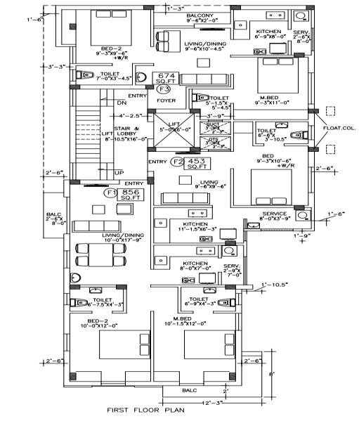
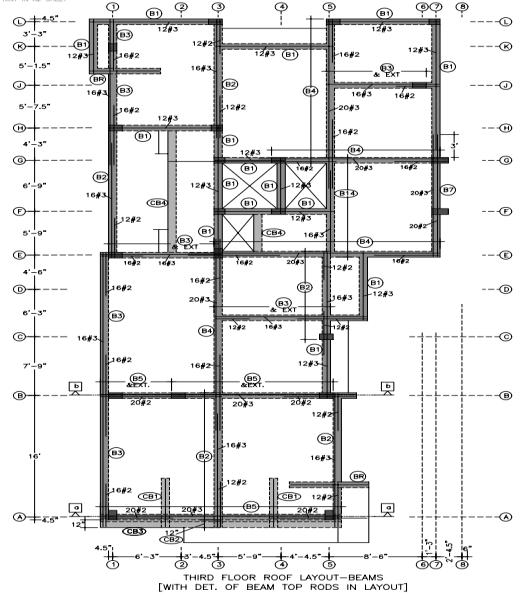
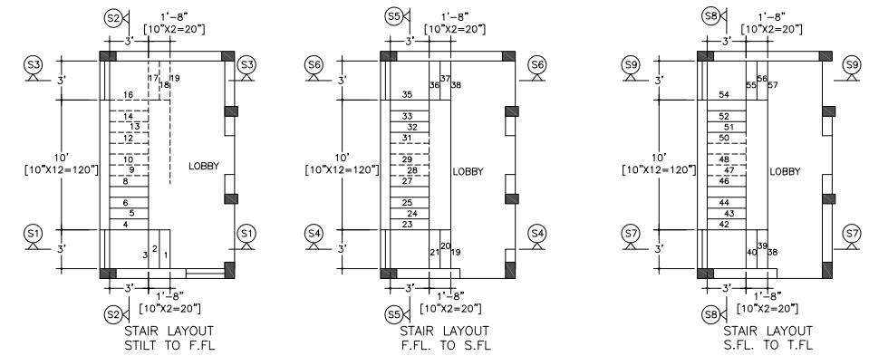
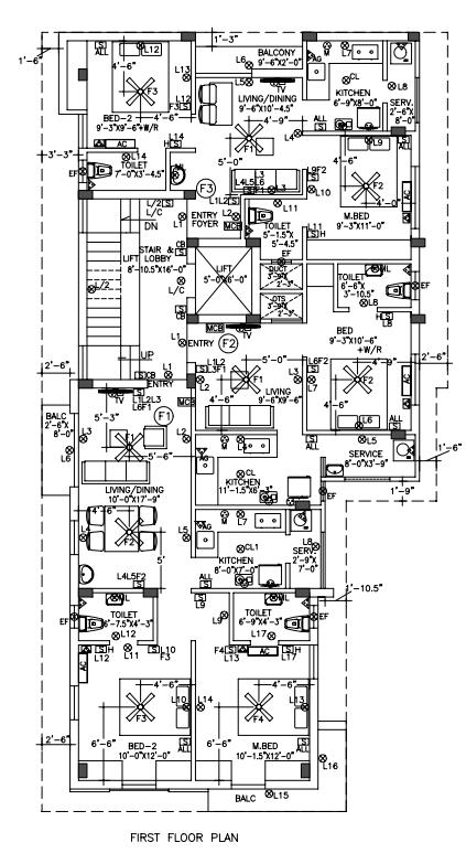
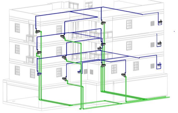
ThefirstphaseofthestudyinvolvedcollectionofArchitectural,Structural,PlumbingandElectricaldrawingsofa three-flooraccommodation building oflandarea 2000squarefeet. Architectural drawingsincludedsiteplan, floorplans, sections and elevations.Structural drawings contained detailsof footing,columns, plinthbeam,lintels,staircaseandroof slab arrangements etc. Electrical drawings provided information on electrical circuits, wiring, connections, switches, fixtures, fans, lighting, air-conditioning or heating systems and the load capacity in the building. Likewise, marking and location of plumbing fixtures like water pipes, drainage and sanitary pipes etc. was displayed in plumbing drawings. SampledrawingsweredisplayedinFigures2to5.
AutodeskRevitprovidesseveraltemplatesfordifferentdisciplineswhichincludeArchitectural,Structural,Plumbingand Electrical[16].Itconsistsofahugelibraryformodeling,plug-insupports,familyfeaturesandadvanceddatamanagement systems which enables visualization process as well as retraction of building information easier and faster. It enables professionals to capture and analyze the design concepts through 3D visual throughout the construction phase [11] Besides, the changes applied to any view gets automatically updated throughout the model. The construction drawings were exported to Autodesk Revit 2021 to generate three-dimensional models; Architectural model, Structural model, ElectricalmodelandPlumbingmodelofthecasestudybuilding.
International Research Journal of Engineering and Technology (IRJET) e-ISSN:
Using ‘Navisworks 2021’ plugin support in Autodesk Revit platform, the four interdisciplinary viz., Architectural, Structural,ElectricalandPlumbingmodelsgeneratedinRevitformat(.rvtfiles)wereconvertedtoNavisworksfileformat (.nwc files). These multiple NWC files from different disciplines were first imported into Autodesk ‘Navisworks Manage 2021’softwareandintegratedintoasinglemodel[11] Differentinter-modelcombinationswereusedforclashdetection asillustratedinTable1. Intra-modelcombinationswerenotconsideredinthepresentstudyastheyresultedinnullclash. The‘ClashDetective’featureofNavisworkswasusedtoperformclashdetectionin themergedmodelsusingdefaultand customized clash rules [11]. This tool enables search through complete 3D project model and helps in effective identification, inspection and reporting of cross-discipline interferences (clashes) in the design stage itself besides reducingtheriskofhumanerror.
Generally,clashresolutionwasatediousprocessinvolvingin-depthknowledgeaboutthedifferentdisciplines. Theclash reports generated in Navisworks were carefully analyzed to understand the cause of each conflict between the interdisciplinarymodels. The‘ElementID’intheclashreportenabledeasyidentificationofclashesinRevitandexpedited theclashresolutionprocess.
International Research Journal of Engineering and Technology (IRJET) e-ISSN:2395-0056
Volume: 11 Issue: 05 | May 2024 www.irjet.net p-ISSN:2395-0072
International Research Journal of Engineering and Technology (IRJET) e-ISSN:2395-0056
Volume: 11 Issue: 05 | May 2024 www.irjet.net p-ISSN:2395-0072
3. Results and Discussion
Thepresentstudyinvolvedclashdetectionbetweenmulti-disciplinary3Dmodelsofafour-storeyresidentialbuildingand subsequentresolutionofthoseclashes
3.1 Creation of 3D Models
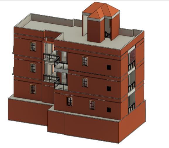
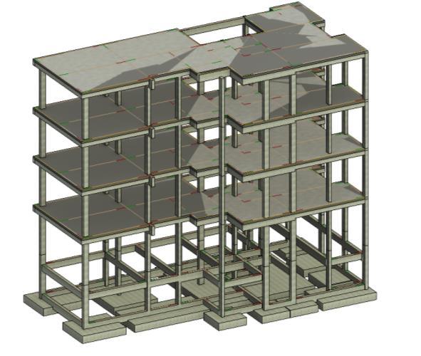
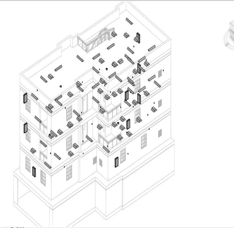
Thebuildingdrawingswereusedtodevelopfourdifferenttypesof3DModelsviz.,Architecturalmodel,Structuralmodel, ElectricalmodelandPlumbingmodelsforthecasestudybuildingusingRevitsoftwareasshowninfigures6to9
3.2 Integration of multidisciplinary models in Navisworks
Thearchitectural,structural,electricalandplumbingmodelsofthecasestudybuildingwereexportedtoNavisworksand integratedintoasinglemodelasshowninfigure10whichwasthenusedtoperformclashdetection.
3.3 Clash detection using Navisworks
ClashdetectionfortheintegratedbuildingmodelwasaccomplishedusingNavisworkssoftware. Theclashesbetweenfour disciplinesviz.,Architectural,Structural,Electrical andPlumbingwereperformedinsixcombinationsandthe numberof clashesdetectedwasillustratedinTable2.
International Research Journal of Engineering and Technology (IRJET) e-ISSN:2395-0056
Volume: 11 Issue: 05 | May 2024 www.irjet.net p-ISSN:2395-0072
International Research Journal of Engineering and Technology (IRJET) e-ISSN:2395-0056
Volume: 11 Issue: 05 | May 2024 www.irjet.net p-ISSN:2395-0072
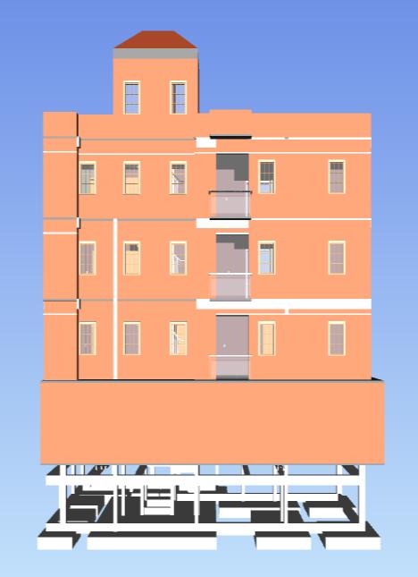
Table – 2: Clashesdetectedbetweendifferentdisciplines
Interdisciplinary Models used for clash test
Architectural versus Structural
No. of Clashes detected
187 74%
Architectural versus Electrical 11 4%
Architectural versus Plumbing 24 10%
Structural versus Plumbing 27 11%
Structuralversus Electrical 2 1%
Electricalversus Plumbing Null clash 0%
/ Common clashes identified
Structuralframing elementrunningwithina wall
Lightingfixtures interferingwithceilings
Pipelinesembedded throughwall
Change in the height or thickness ofarchitecturalelements.
Relocate or reroute or lower electrical elements with drops and junctions.
Reroute or relocate or resize plumbingelements.
Pipelinesroutedthrough beam Reroute or relocate plumbing elements.
MisplacementofElectrical elements
Relocate or Reroute or lower electrical elements with drops and junctions.
Overall 251 hard clashes were detected, with maximum of 187 clashes between Architectural and Structural models. Lowest number of clasheswasobserved between Structural andElectrical models. Noclashesor null clashwas obtainedbetweenPlumbingandElectricalmodels. Theseclashesifnotdetectedatthedesignstageitselfwouldposehigh risk during executionresultinginprojectdelayandincreaseincost. Thedistributionofclashpercentageamongvarious interdisciplinary models was shown in the Figure 11 A similar study also showed major clashes of about 192 between Architectural and Structural elements, 10 between MEP & Structural, and 6 between MEP & Architectural elements [14] Likewise, nearly 1800 clashes were detected between Architecture, Structure and Sanitary in a case study on the MalaysianPoliceHeadquarterBuildingusingBIM[11]
International Research Journal of Engineering and Technology (IRJET) e-ISSN:
Volume: 11 Issue: 05 | May 2024 www.irjet.net p-ISSN:2395-0072
Architectural versus Structural
Architectural versus Electrical
Architectural versus Plumbing
Structural versus Plumbing
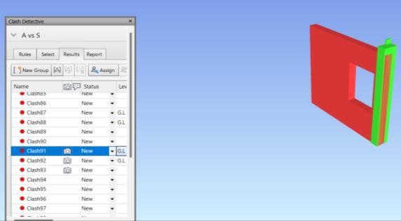
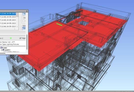
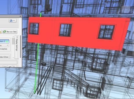
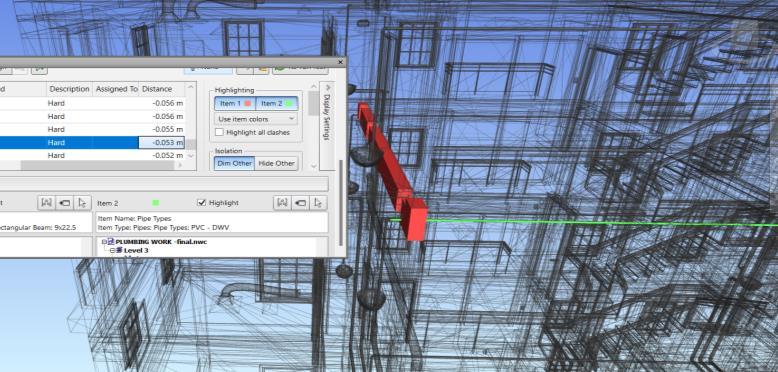
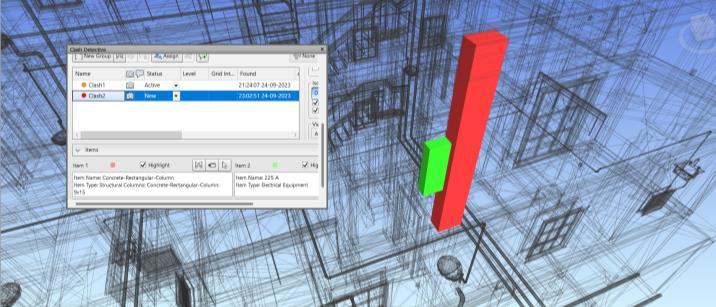
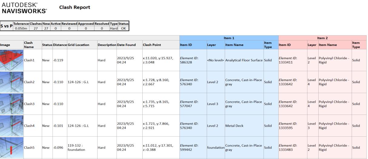
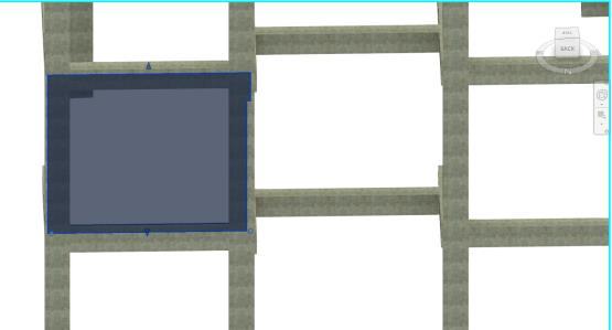
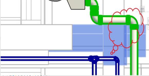
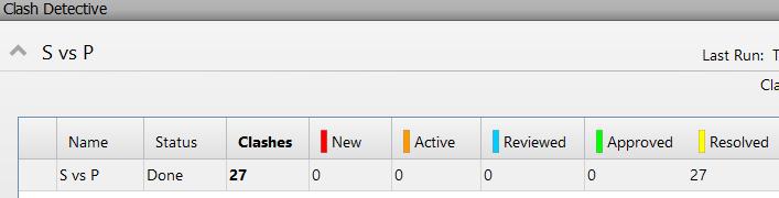
The clashes identified between interdisciplinary models were analyzed and same has been illustrated in Table 2 Some commonconflicts noticed were: structural elementsrunning through wall,wrongplacementof electrical fixtures inroof, improperroutingofplumbinglinesthroughstructuralelementsetc. ThemajorclashidentifiedbetweenArchitecturaland Structural models viz., interference of wall and column was displayed in Figure 12. Likewise, Figure 13 shows the clash betweenArchitecturalandElectricalmodelsviz.,clashbetweenceilingandlightingfixtures. Thegreencolorpointsoutto lightingfixturewhileredcolourindicatedceiling. TheclashbetweenArchitecturalandPlumbingmodelswasillustratedin Figure14whereingreencolourrepresentedpipelineandredcolourshowingthewall. TheclashbetweenStructuraland Plumbing models due to improper routing of plumbing lines was displayed in Figure 15. The green color designates pipeline and red color indicates beam. Similarly, clash between Structural (column) and Electrical (lihting fixture) was showin in Figure 16. The green color indicated electrical equipment while red color indicates column. A sample clash report as shown in Figure 17 was clearly indicative of the type of clash, status, element ID etc. which was helpful in identifyingandresolvingtheclashes.
International Research Journal of Engineering and Technology (IRJET) e-ISSN:2395-0056
Volume: 11 Issue: 05 | May 2024 www.irjet.net p-ISSN:2395-0072
International Research Journal of Engineering and Technology (IRJET) e-ISSN:2395-0056
Volume: 11 Issue: 05 | May 2024 www.irjet.net p-ISSN:2395-0072
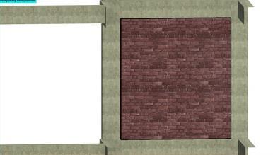
The causes behind each clash were identified and solutions as expressed in Table 2 were arrived to resolve the interdisciplinary model clashes. The ‘Element ID’ generated in the clash reports helped to locate and visualize the elementsinRevitaswellastoresolvetheclasheseasilyandquickly. Changingdimensionsofarchitecturalelementsand relocating or rerouting plumbing and electrical fixtures were some solutions which helped to resolve major number of clashes. Forexample,figure18showsthatclashbetweenwallandcolumnwasresolvedbychangingthewalldimensions. Likewise,pipelinespassingthroughbeamwerethecommonclashbetweenstructuralandplumbingmodels. Withasingle relocationofpipeline,wecouldresolvehighernumberofclashes. Forexample,whenasinglerunofpipelineclasheswith fivebeams,itappearsas5clashesintheclashreport,butproperrelocationofthepipelineas exhibitedinfigure19could solveallthe5clashes. Samplereportgeneratedafterresolvingthe27clashes amidStructuralmodelandPlumbingmodel wasshowninFigure20
4. CONCLUSIONS
BuildingInformationModelling(BIM)isdevelopingsignificantlyintheArchitecture,Engineering,andConstruction(AEC) sector, where its current application has a major beneficial effect on projects' performance, timelines, and cost. In this work, clash detection was used in place of the conventional way to identify conflicts in 3D models prior to the start of actual construction. Autodesk Revit and Navisworks Manage were employed to reduce the coordination mistakes and human errors by construction players, which led to high levels of model correctness. Therefore, it is crucial to carry out Clash detection in order to resolve clashes in the model. In this study, totally 251clashes were identified on G+3 model andmajorityofclasheswerefoundbetweenthecombinationofArchitecturalandStructuralmodels Detectionofclashes
International Research Journal of Engineering and Technology (IRJET) e-ISSN:2395-0056
Volume: 11 Issue: 05 | May 2024 www.irjet.net p-ISSN:2395-0072
earlierinthedesignstagehelpstoreducereworkandsavestimeonrealtimeconstruction. Theresearchworkenablesus toenhancetheprojectperformancebydetectingclashesearlierinthedesignstageitselfthussavingthetimeandcostof reworksintheconstructionstage.
[1] Liu X., Zhao J., Yu Y., and Ji Y. (2024) “BIM-based multi-objective optimization of clash resolution: A NSGA-II approach.”JournalofBuildingEngineering,89:109228.
[2] WangJ.,WangX.,ShouW.,ChongH-YandGuoJ.(2016)“Buildinginformationmodeling-basedintegrationofMEP layoutdesignsandconstructability.”AutomationinConstruction,61:134-146.
[3] AkponewareA.O.andAdamuZ.A.(2017)“ClashDetectionorClashAvoidance?Aninvestigationinto coordination problemsin3DBIM.”Buildings,7(4):75.
[4] Luo S., Yao J., Wang S., Wang Y. and Lu G. (2022) “A sustainable BIM-based multidisciplinary framework for undergroundpipelineclashdetectionandanalysis.”JournalofCleanerProduction,374(10):133900.
[5] HsuH-C,ChangS.,ChenC.C.,andWuI.C.(2020)“Knowledge-basedsystemforresolvingdesignclashes inbuilding informationmodels.”AutomationinConstruction,110:103001.
[6] Bockstael D. and Issa M.H. (2016) “A Methodology for Contractor Clash Detection Using Building Information ModellingonCommercialBuildingConstructionProjects.”JournalofInformationTechnologyinConstruction,21: 233-249.
[7] Akhmetzhanova B., Nadeem A., Hossain M.A and Kim J.R. (2022) “Clash Detection Using Building Information Modeling(BIM)TechnologyintheRepublicofKazakhstan,”Buildings,12(2):102.
[8] Savitri D.M., Juliastuti, and Pramudya A.A. (2020) “Clash detection analysis with BIM-based software on midrise buildingconstructionproject.”IOPConfSeries:EarthandEnvironmentalScience,426:012002.
[9] Hu Y., Castro-Lacouture D., and Eastman C.M. (2019) “Holistic clash detection improvement using a component dependentnetworkinBIMprojects.”AutomationinConstruction,105:102832.
[10] Hu Y., Castro-Lacouture D., Eastman C.M., and Navathe S.B. (2020) “Automatic clash correction sequence optimizationusingaclashdependencynetwork.”AutomationinConstruction,115:103205.
[11] Kermanshahi E.K., Tahir M.B.M., Lim N.H.A.S., Balasbaneh A.T., and Roshanghalb S. (2020) “Implementation of Building Information Modeling for Construction Clash Detection Process in the Design Stage: A Case Study of MalaysianPoliceHeadquarterBuilding.”IOPConf.Series:EarthandEnvironmentalScience476:012009.
[12] Parn E.A., Edwards D.J., and Sing M.C.P. (2018) “Origins and probabilities of MEP and structural design clashes withinafederatedBIMmodel.”AutomationinConstruction,85:209-219.
[13] Soundarya R. and Uma R.N. (2017) “Building Information Modelling of a Two Storey Building using Autodesk RevitandAutodeskNavisworkManage.”InternationalJournalofCivilEngineering(IJCE),6(4):33-46.
[14] PoojithaandThamilselviP.(2021)“ClashdetectioninamultistoreybuildingusingBIMapplication.”International JournalofMultidisciplinaryEducationalResearch,10(5):36-48.
[15] ChahrourR.,HafeezM.A.,AhmadA.M.,SuliemanH.I.,DawoodH.,Rodriguez-TrejoS.,andDawoodN.(2021)“CostbenefitanalysisofBIM-enableddesignclashdetectionandresolution.”ConstructionManagementandEconomics, 39(1):55-72.
[16] Johansson M., Roupé M., and Bosch-Sijtsema P. (2015) “Real-time visualization of building information models (BIM).”AutomationinConstruction,54:69-82.