
International Research Journal of Engineering and Technology (IRJET) e-ISSN: 2395-0056
Volume: 11 Issue: 05 | May 2024 www.irjet.net p-ISSN: 2395-0072
International Research Journal of Engineering and Technology (IRJET) e-ISSN: 2395-0056
Volume: 11 Issue: 05 | May 2024 www.irjet.net p-ISSN: 2395-0072
Tayyib Raila1 , Viresh G Patil2 , Syed Tauqeed Ahmed3 , Uzair Jalali on t Size 12
Porf. Vaijanath Patil5 , Dr. Rajendra M Galagali6 , Prof. Vishwanath M. K
1,2,3,4 Students, Department of Mechanical Engineering, S.G. Balekundri Institute of Technology, Belagavi, Karnataka, India
5Professor and Project Guide , Department of Mechanical Engineering, S.G. Balekundri Institute of Technology, Belagavi, Karnataka, India
6Professor and HOD, Department of Mechanical Engineering, S.G. Balekundri Institute of Technology, Belagavi, Karnataka, India
7Professor and Project Coordinator , Department of Mechanical Engineering, S.G. Balekundri Institute of Technology, Belagavi, Karnataka, India
Abstract - Comfort coupled with safety and simplicity is what man strives for. Our project has been to bring about both the eliminate human efforts in the industry our effort has resulted in development of a new "Hydraulic Paper Plate Cutting Press with Multiple Die". The project present a basic as well as very professional treatment of the subject in a very comprehensive, based on learning effort and understanding capability of today as per their levels. The process is simple and comfortable. Basic calculation, drawing, designing is included in the project. The salient features of our process can be listed as the mechanism used is very simple, easy for operation.
Linear actuators that transform fluid into mechanical power are called cylinders. They go by the names JACKS and RAMS as well. High pressure is applied to hydraulic cylinders, which result in significant forces and accurate movement. As a result, they are built to endure great forces and are made of sturdy materials like steel. Pneumatic cylinders can only be used at pressures of about 10 bar since using them at higher pressures can be hazardousduetotheexpandingnatureofgas.Asaresult, they are made of lighter materials like brass and aluminum. It is challenging to accurately control the velocity of a pneumatic cylinder since a gas is a compressible material.Pneumaticandhydraulic cylinders operate on the same fundamental theories. The mechanicalpressworkwasdonebythisequipment.
It is made up of a hydraulic cylinder. According to the hydraulic circuit, oil passes through each component and begins to flow outward when the hand pump lever is pulled. This oil is connected to the P-port of the direction control valve, which drives the cylinder piston rod forward. The direction control wall conspiring of "P" port to "t" port, which is in the generally assisted position direction, can bechanged,ascanthedirectionofthefluid flowing, using the hand-operated direction control valve. The oil is connected from port "P" to port "T" when the
lever is pulled outside, changing the valve's direction. Reversing the direction of oil flow causes the piston to go backward.
This completes the forward movement. The primary function of the press is to bring the ram to the home position.Todothis,thehandleverofthedirectioncontrol valve is pushed inside, changing the direction from P to B andAtoT.
I. Tomakeadevicewhichissuitableeconomicalfor small Scale industries: taking in to consideration the cost factor this device is suitable for small scaleaswellasbigscaleindustries
II. Takingsafetyasprimeconsideration: This device issaferinallrespects.
III. To build a device which can bend, cut, shape etc withoutapplyinggreaterforce
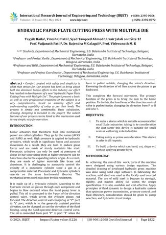
In achieving the aim of this work, parts of the machine were designed using various design equations. The detailed drawing of developed hydraulic press machine was done using solid edge software. In fabricating the machine, mild steel was used as the locally used sourced material. The use of mild steel is because its strength, rigidity, and machin ability fall within the design specification. It is also available and cost-effective. Apply principles of fluid dynamic to design a hydraulic system that optimizes power transmission, pressure control, and fluid efficiency. Consideration should be given to pump selection,andhydrauliccircuitdesign.
International Research Journal of Engineering and Technology (IRJET) e-ISSN: 2395-0056
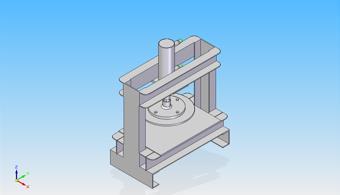
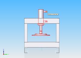
DesignofHydraulicpressmachine
SideView
TopView
CALCULATION:
DeterminationofVolumeofHydraulicTankis V=LWH.
The diameter of bolt was determined from equation accordingtoKhurmiandGuptaat2005is P=π4(dc)2ςtn.
Where P=Externalloadactingon
Coverplate
dc=isthecorediameterof thebelt
but, P=π4(D)2p��=π4(��)2��(3)
Determinationof tensilestressduetostretchingof bolt is Pi=2840d(N) ����=2840��(��).
Determinationofstressareaonthebeltis
Area=π4(dp+dc2)2 D=Pitchdiameter
DETERMINATION OF WEIGHT OF THE PISTON OF THE HYDRAULIC PRESS:
TheweightofpistonwasdeterminedfromEquation(6)
Density of metal (ρ)=Mass of metal(m) Volume of piston(V)p
TheweightofpistonwasdeterminedfromEquation
Density of metal(ρ)=Mass of metal(m)Volume of piston(V)p/Massofmetal(��)Volumeofpiston(��)��
Butdensityofmetal ρm = 7850 kg/m3
Volumeofpiston (Vp)=πr2h (����)=π��2ℎ.
MassofPiston, Mp = ρmVp����=��������.
AndWeightofPiston(Wp)=mpg.
Determination of the Weight of Press Cylinder:
The weight of press cylinder was determined by applying Equation.
Weightofcylinder (Wc)=ρmVcg (����)=��������g. whereVc=isthevolumeofcylinder.
Vc=π(r22−r12)h.
DETERMINATION OF OIL FLOW RATE:
OilflowrateofthepumpwasdeterminedusingEquation Q=AV��=����
whereQistheflowrateinm3/s,Visthevelocityofflowin m/s,Aistheareaofpipeinm2
Equation(12)wasusedtodeterminethehydraulic power ofthemachine
HydraulicPower Ph=Qρgh��ℎ=������ℎ
where Q is the flow rate in m3/s, ρ is the density of oil in kg/m3,gistheaccelerationduetogravityinm/s2,histhe differentialheadinmeters(m).
Volume: 11 Issue: 05 | May 2024 www.irjet.net p-ISSN: 2395-0072 © 2024, IRJET | Impact Factor value: 8.226 | ISO 9001:2008
International Research Journal of Engineering and Technology (IRJET) e-ISSN: 2395-0056
Volume: 11 Issue: 05 | May 2024 www.irjet.net p-ISSN: 2395-0072
SPECIFICATION OF FRAME:
Height:740mm.
Width:350mm.
C-channel:100x50mm.
Capacity:10tons.
Heightofthecylinder:260mm.
MATERIALS USED IN PROJECT:
i HydraulicCylinder10ton.
ii Hosepipe’scoupling&Fitting
iii PaperPlatedies
iv HydraulicHandPump
v IronRoad
WORKING PRINCIPLE: Oil circulationistherethroughall components as per hydraulic circuit, after operating the lever of hand pump, the oil coming from inlet to outlet of hand pump and outlet port is connected to port of direction control valve and direction control valve conspiring port to port normally aided position of directioncontrolvalve.Whenpullingtheleveroutside,the change of direction of valve from port to port, where one port is connected to another port connected to forward line of cylinder at that time ram moves down and shears sheetmetal.
The cylinder is 40*25*130 stroke. 40mm is cylinder bore 25mm is piston rod diameter size. For sheet press pressure required is 234 Kg/cm^2 in tons 1075 ton capacityofsixcylinderrequired75*40andstrokeis150.
DESIGN PROCEDURE:
i FunctionalDesign.
ii ProductDesign.
iii EngineeringDesign.
A designer may take the following steps while creating a newproductoroneofitscomponents:
i Provide a thorough description of the issues at hand, being as specific as possible. Include the reasonbehindthemachine'sdesign.
ii Choosethepotentialmechanismthatwillprovide thedesiredmotion.
iii Ascertain the force applied to it and the energy thateachmachinecomponenttransmits.
iv Choose the material that fits each machine componentthebest.
v Calculate the permissible or design stress while taking into account every element that influences themachinepart'sstrength.
vi Determine the machine's significance,necessity, andapplication.
vii Issueswiththemachine'scurrentrequirements
DESIGN OF BOLT:
Bolt is to be fastened tightly also it will take load due to rotation.StressforC-25steelft=120N/mm^2Stdnominal diameterofboltis8mm.
Letuscheckthestrength:-
Alsoinitialtensionintheboltwhenbeltisfullytightened.
P=1420dN
P=1420*8N
P=1420dN
P=11360N
Thereforethetotalloadonbolts
P=11360/500N
P=11860N
Beingthefourboltstheloadissharedas
P=11860/4 =2965N.
2965=(Pi/4dc^2)*ft
2965=(Pi/4)(8*0.84^2)*ft
Ft=83.59N/mm^2
DESIGN OFCYLINDER BODY:
Material Used - Mild Steel. The chosen Bore diameter of the cylinder is 40mm The cylinder Bore diameter has finished attaining the capacity of machine under safe workingstress.SincetheHydraulicpressureis16MpaWe knowthat
P=F/A Where PressureinN/mm
F-ForceinN
A-Areainmm
Therefore
16-F/(pi/4*40^2)
International Research Journal of Engineering and Technology (IRJET) e-ISSN: 2395-0056
F=(pi/4*40^2*16)
F=20.10619KN
Tofindthethicknessofthecylinderbody
For closed end cylinder- Clavarino's equation (D/2) {[(ft+ (1-2p)P/(ft.(1-p)P)1-11
Where 1 thickness of cylinder body D, Inner diameter of the cylinder body 40mm Working pressure 16 Nirah F, Allowableworkingstress461N/mm²FosFactorofSafely Therefore-461/4115.25N/b
µ=Possionratio=0.3=(D/2)(sqrt(V)*\{(ft+(1-2mu)* P / (ft - (1 - mu) * P)) - 1\}=(40/2)(v\ (112.25 + (1 - 2 * 0.3) * 16 / (115.25 - (1 + 0.3) * 16) - 1) t = 20sqrt(121.65/94.45)–1.
t=2.695mm
Forsafethicknessadoptedis15mxn
Outerdiameterofcylinder
D{g}-D{I}+(2t)
D{9}=40+(2*5)
D{0}=40+10
D{6}=50mm
Thecylinder50/40isused.
DESIGN OF RAM:
MaterialUsed-MildSteelGradeEN-Sbar(carbon%0.45)In order to overcome frictional resistance more force must beexertedontopoftherambyfluid
-\{(pi/4)*d^2*16\}
-((pi/4)*40^2*16)
F=20.106KN
Load-F-AxP The tensile stress of the material is 135.5N / m * m ^ 2 Also F-Ax 20.106 x 10 = ((x/4)xd,x135.5) d, (20.106 x 10'x4)/(x 135.5) d{p} - 13.74mm But for safe and standard rods, therefore the diameter of piston is d_{2}+25mm
TocheckforshearstressE-26
ThethreadsofM20with1.Sompitchischosen
Corediameterof25it-18.093s
tmp/2
15/2
0,75mm
numberoftheForEN-3bar1025MPa(frommushar wall in data t{y} = 20106.19 / (pi * 16.933 * 0.75n)
n=20106.19/\pi*16.933*0.75*90.25)5.586Lengthof threadsnp=6*1.59mmButthelengthchosenis20mm.
Let t, be thickness of end cover Force on cylinder end cover
F-Dxtxa
Wheretensilesetsformildsteedc-107.5Mpa
F-2010619N
ThereforeF-DxLx20106.19-40x14x107.5
L-2010619/(40x107.5)4-4675mm
But due to threading and welding corrections of the end coverthethicknesshastobeparticularlymaintained
Hence242.7PistonHead
The design of piston head is designed where dieter of pitch<-39.970/39.94
Clearance of 0.004 for dimensions and clearance between andputheadis01026whichiskeptforsliding
THE
1)Strokelengthof150mmhastobeintercoal.
2)SealsaretobefixedfornoleakageTocheckbucklingof pistonrod.Thepistonhastwoats
1.Pistonhead
2Ram
Thelengthoframis165mmUsingtherankine'sformula.
P(A)/(1+(1/K))
radiusofgyration(B/A)
d,compressivestress
1.effectivelength
Foroneandfixed&otherendfree
1-212x165330mex
280Nmand25ms
A-x/4(d)x/4(25)4903875mm2x/(64x15" -19174.75mmKH/A)19174759490873)
6:25
WhereYoung'sModulas-207x10m
A-280x207x10)-1.3708x10
Therefore
P-1250x400573)(11.3705410(330/6251)
Since the critical load for buckling455&pping 2016 which islessandhencesosala.
Volume: 11 Issue: 05 | May 2024 www.irjet.net p-ISSN: 2395-0072 © 2024, IRJET | Impact Factor value: 8.226 | ISO 9001:2008
International Research Journal of Engineering and Technology (IRJET) e-ISSN: 2395-0056
Volume: 11 Issue: 05 | May 2024 www.irjet.net p-ISSN: 2395-0072
When material is being pressed the toe rod is in direct tension,using4tierods.
F=F/4
=20.10619*10^3/4
=5.0265*10^3*N
F=A*sigma
Wheretensilestress100.25N/mm²
5.0365x10³-(π/4xd²)x100.25
d(5.0365x10x4)/(πx100.25)
d_{1}=7.99mm
Tofindthenominaldiameter
d{1}=7.99/0.84
d{1}=9.511mm
Asthe weight of upper framecylinder assemblyhasto be supportedbypillarsandmustbestableandrigid
Thereforetaked,10mm
Thecylindertierodistakenas10mm.
PUMP SPECIFICATION:
MODLE:Hp-3
FLOWRATE:Flowcapacity-3liters
TANKCAPICITY:Oiltank-30liters.
PRESSURE:MaxWorkingPressure-350bar.
ADVANTAGES:
i The ability to process several pieces at once using multiple dies boosts overall productivity and cuts down on production time.
ii The hydraulic press's application range is expanded by the use of different dies for shaping, cutting, and punching, among other activities.
iii Higher production rates and enhanced efficiency can lower the total cost per item even with the initial investment in several dies.
iv Every die can be made for a particular task, guaranteeing excellent accuracy and uniformityinthepiecesthatareproduced.
v Becausenumerousdiesmaybesetupatonce, manufacturing runs can be completed with lessdowntime,whichboostsoutput.
vi The hydraulic press can generate a larger volumeofpartsinagivenamountoftimeifit hasmanydies.
i Managing multiple dies in a hydraulic press setup increases the complexity of the system. This complexity can lead to more maintenance requirements,higherchancesofmalfunction,and increased downtime for troubleshooting and repairs.
ii The initial cost of setting up a hydraulic press with multiple dies can be higher compared to a single-die system. Additionally, the cost of maintaining and replacing multiple dies adds up overtime.
iii Accommodating multiple dies within the workspace of the hydraulic press requires more space, which might not be feasible in all manufacturing environments. This can limit the scalabilityoftheoperationornecessitatealarger facility.
iv Changing between different dies can be timeconsuming, especially if each die requires significantadjustmentsorcalibration.Thissetup time can reduce overall productivity and increaseproductionleadtimes.
v Although having several dies increases versatility, in some situations it might also reduce the hydraulic press's adaptability. Changing out dies frequently might not be appropriate for small-batch manufacturing or quickproductionadjustments.
vi Every extra die increases the workload for maintenance. Regular inspection, cleaning, and possiblerepairsarenecessarytokeepnumerous dies operating at peak efficiency. These tasks mightraiseoperatingexpensesanddowntime.
vii Operating a hydraulic press with multiple dies may require more specialized skills and training for personnel. This can add to the training costs andmaylimitthepoolofqualifiedoperators.
viii With multiple dies, there is an increased risk of misalignment, which can result in defective products, material waste, and potential damage tothepressitself.
International Research Journal of Engineering and Technology (IRJET) e-ISSN: 2395-0056
Volume: 11 Issue: 05 | May 2024 www.irjet.net p-ISSN: 2395-0072
We have taken this project up as a real challenge, as we were not experienced in the hydraulics field. We began ourworkonthisproject,initiallyfacingnewhurdles.After the completion of the project, we tried to work in our collegemachineshop,andwewerepleasedtonotethatit meets the requirements for what it is meant. It can easily cuttheboltsandnutswithoutapplyingmuchforce
Themaneuverabilityofthedeviceisgood,anditshandling is simple. For commercial purposes, the efficiency of the devicecanbeeffectivelyimprovedbyincreasingitssize.
To maximize the commercial potential of a device, there areseveral otherways toincreaseitsefficiency,including upgradingitscomponentsandoptimizingitssoftware.
The We are highly thankful to Dr. B.R. Patagundi, Principal, SGBIT, Belagavi forprovidingtheopportunity forbuildinganddemonstrationoftheproject.
We would like to express deep sense of thanks and gratitudeto Dr. Rajendra M Galagali, HOD, Department of Mechanical Engineering, SGBIT, Belagavi for providingnecessarytechnicalsuggestionduringproject.
Wearegratefulto Prof. S.C. Zampa, Associate Professor and Project guide, SGBIT, Belagavi for his continuous valuableguidanceandsupport.
We are thankful to Prof. Vishwanath Kadakbhavi, Assistant Professor, SGBIT, Belagavi forencouraging us in conduction and generous support during the conductionoftheproject.
Finally, we are thankful to the staff of Department of Mechanical Engineering, SGBIT, Belagavi for their support.
:
i T. Patel, S. Sheth, P Patel, “Design and semiautomatic hydraulic blanking machine using PLC”,3rd nationalconferenceoninnovation& emergingtechnology.
ii W. Boltan, Programable logic controller, Elsevier’sscience&technology.
iii M. Cechura, J. Stanek, M. Cirek, J. Hlavac, V. Kubec, Z. Chval, Final Report of Activity in Year2008,Pilsen:ZČU,2008.
iv S. Mrazek, Production of Forgings for Wheel sets- as a Part of Czech Forging Indurstu,
Kovarenstvi, ISSN 1213-9289 Brno, 2013, pp.79-83.
v http://www.cvts.zcu.cz, (2013), University of WestBohemia,Accessedon:2013-07-15.
vi H. S semakula, Manufacturing of Heavy Rings and Large Copper Canisters by Plastic Deformation,Stockholm,2003,pp.6–22.
vii M..Cechura, J. Smolik, Development and Innovations of Existing Design Solutions of Forming Machines, research report, CK-SVTWP11,CVTS,Pilsen,2012.