
Seismic Analysis of Braced Frame with Different Base Condition
Shivashankar Vadekar1 , 2B. P. Annapurna
1Research Scholar, Department of Civil Engineering, UVCE, Bangalore University, Bangalore, Karnataka, India.
2Professor, Department of Civil Engineering, UVCE, Bangalore University, Bangalore, Karnataka India
Abstract: The use of base isolators helps the structure to mitigate the lateral forces like wind and seismic etc. by expanding the vibration period of the structure. The lateral forces are also resisted by the use of special measure known as steel bracing. Steel bracing decrease the horizontal deformation by increasing the vertical stiffness and stability. In the current study, analysis of RC frames with different base conditions (Fixed, HDRB and LRB) along with different types of bracing (X type, Forward diagonal type and backward diagonal type) is carried out using response spectrum method. For this study, G+10 multi-storey building is assumed and is situated at seismic zone V. modelling and analysis of the building frame are carried out in Etabs software (2015 version). From the present study, it is observed that Lead Rubber Bearing Base isolators with completely X bracing (E type) is most suitable.
Key words:- HDRB,LRB,Forwarddiagonaltype,BackwarddiagonaltypeandXtype,basedrift,storeyshear,stiffness
1. INTRODUCTION
As India is developing country, the infrastructure of the country is modernizing rapidly and also increase in population of the country leads to growth to the population density. To meet the desire of the people of land for construction (housing, commercial building and other buildings) is fulfiled only with the vertical development i.e. multistory buildings. Along with the vertical development, it is responsibility of every engineer to mitigate the forces like seismicandwindetc.whichareunfavorableforstructuresafety.Astheheightofthebuildingincreases,thedeformationofthe building also increases. So it is necessary to recommend special measures to reduce these kind of deformation and thebase isolation techniqueis one of thespecial measures to takea run at mitigation of deformation of thebuilding. Anothermeasure to oppose lateral force is steel bracing, it resist horizontal forces by increasing its vertical stiffness. There arevarious types of bracing systems like Forward diagonal type, backward diagonal type, X type, V type, inverted V type, K type, diagonal type and so on. In the present study, the effect of base isolators i.e. HIGH DAMPING RUBBER BEARING andLEAD RUBBER BEARING along with different types of bracing i.e. Forward diagonal type, backward diagonal type and Xtype are located in different position of the frame member are studied. The behavior of building is studied under thefollowing results i.e. storey drift, base shear, storey displacement and Fundamental time period of building and comparedwithbuilding withfixedbasewithoutanybracing.
2. OBJECTIVE
a) TenstorybuildingisanalyzedinEtabssoftwarewithoutbracingsandwithdifferentbracingsystems.
b) Comparethereactionofdifferentbracedandunbracedframesubjectedtohorizontalloads.
c) Identifytheeffectivebaseconditionandbracingsystemtoresistthelateralloadseffectively.
d) Toidentifytheeffectivetypeofbracing.
e) Typesofbracing: Forwarddiagonal,backwarddiagonalandXtypesbracingsystemsareused.
International Research Journal of Engineering and Technology (IRJET) e-ISSN: 2395-0056
Volume: 11 Issue: 01 | Jan 2024 www.irjet.net p-ISSN: 2395-0072
3. MODELLING
Thefollowingaretheplanandelevationofthebuilding.

4. PARAMETERS CONSIDERED IN THE STUDY
4.1 Types of bracing and its representation.
1.Xbracing [X]
2.Forwarddiagonalbracing [ ∕ ]
3.Backwarddiagonalbracing [ \ ]
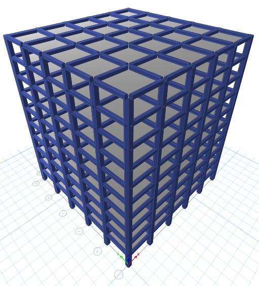
4.2 Position of bracing and its representation.
1.Withoutbracing. Model-[A]
2.WithalternativeXbracing. Model-[B]
3.Withforwardandbackwarddiagonalbracing. Model-[C]
4.Withforwarddiagonal,backwarddiagonalandXbracing. Model-[D]
5.WithcompleteXbracing. Model-[E]
4.3 Types of isolators and its designation.
1. FixedBase F
2. HDRB H
3. LRB L
Table 1:BuildingDescription
5. Results and Discussion:
5.1 Fundamental Time Period
The fundamental time period for all models obtained from the modal analysis, which estimate the time period with respecttomassandstiffnessofthestructure
2: Fundamentaltimeperiodofframefordifferenttypesofbracingandbasecondition
International Research Journal of Engineering and Technology (IRJET) e-ISSN: 2395-0056
Volume: 11 Issue: 01 | Jan 2024 www.irjet.net p-ISSN: 2395-0072


TheaboveChart4andtable2showsthefundamentaltimeperiodofthebuildingwithdifferentbracingsandwithout bracings.
The time period for different base condition with different position of bracing, the LRB shows the maximum time periodandfixedbaseshowstheminimumtimeperiod.TheincreaseintimeperiodofHDRBandLRBisolatorswithrespectto fixedbaseconditionis 1.8 times and 2.12 times respectively.Hence,fixedbaseisstifferandLRBislessstiff.Amongall types of bracing, E-type bracing has less time period and frames with C-type bracing has more time period which indicate E-type bracingisstifferandframeswithC-typebracingislessstiffer.
5.2 Base Shear
Theseismicgroundmotioncausethemaximumexpectedhorizontalforceatthebaseofthestructure.
Table 3: BaseShearofframefordifferenttypesofbracingandbasecontion
Shear


TheaboveChart2andtable3showstheBaseShearofthebuildingfordifferentbaseconditionwithdifferentbracingsand withoutbracings.
It is observed that, the base shear is reduced in frames with base isolation models, LRB has reduction of 49.606% whereasHDRBhasreduction 42.678% baseshearwithrespecttofixedbasecondition.Thereductioninbaseshearinmodels withbaseisolatedcomparetomodelswithfixedbasemodelsisduetohighertimeperiod. ThetypeofbracingconsideredEtypebracinghashigherbaseshearforallbaseconditionandC-typebracingshowstheleastbaseshearforallbasecondition. Comparetothebaseisolator,LRBbaseisolatorismoreflexiblecomparetoHDRBisolatorsandfixedbase.Comparetotypeof bracing,E-typebracingisstiffer.HenceLRBbaseisolatorwithE-typebracingisthebest.
5.3 Storey Displacement.
Thedisplacementofthestructureinlateraldirectionduetosomeexternalforcetoreducethedisplacementcausedbylateral loadbyusingbracingsystems.
Table 4:Displacementofframefordifferenttypesofbracingandbasecondition.


ModelModelModelModelModel-
TheaboveChart3toChart6andtable4showsthedisplacementofthebuildingwithdifferentbracingsandwithout bracings.
The storey displacement increases as the heigth of the building increases. From above figures it can be said that models with bracing shows the less displacement than models without bracing. By using base isolators, HDRB isolators reduces the displacement by 27.67% and LRD isolators reduces the displacement by 36.46% with respect to fixed base model.AsthedisplacementinthebuildingisleastfortheLRBwithE-typebracingshowstheleaststoreydisplacementamong alltheothertypeofbracing.Fromtheandfigure(7,8&9)showsthestoreydisplacementvsstoreyheigth,itisobservedthat
International Research Journal of Engineering and Technology (IRJET) e-ISSN: 2395-0056
Volume: 11 Issue: 01 | Jan 2024 www.irjet.net p-ISSN: 2395-0072
among base isolators, HDRB base isolator with C-type bracing shows the more displacement compare to other types of bracingandLRBwithE-typebracingshowstheleastdisplacement,whichcanbemostrecommended.
5.4 Storey Drift
Itistheratioofdisplacementoftwoconsecutivefloorstotheheightofthatfloor.Thebelowgraph2andtable3arethe driftvaluesofthebuildingwithdifferentbracingsystemsandwithoutbracingsystems.
Storey Drift


International Research Journal of Engineering and Technology (IRJET) e-ISSN: 2395-0056
Volume: 11 Issue: 01 | Jan 2024 www.irjet.net p-ISSN: 2395-0072


International Research Journal of Engineering and Technology (IRJET) e-ISSN: 2395-0056
Volume: 11 Issue: 01 | Jan 2024 www.irjet.net p-ISSN: 2395-0072
TheaboveChart7toChart9andtable5showsthestoreydriftofthebuildingwithdifferentbracingsandwithoutbracings.
Thestoreydriftareincreaseduptostorey3andthengraduallydecreased,reachedtoleaststoreydrift attopstorey in fixed base models i.e., 3rd storey for fixed base condition. It is observed that, the storey drift of base isolated models is maximum at first storey due to reduction in stiffness at base level. The storey drift of models with base isolators is less comparedtomodelswithfixedbaseforallthestoreys,exceptfirststorey.Thestoreydriftisincreasedinbaseisolatedmodels by 1.12 times and 1.01 times forHDRBandLRBrespectively.TheE-typebracinghaslessstoreydriftandC-typebracinghas morestoreydriftwhichindicateless.
6. CONCLUSION
1. Amongbaseisolators,TheLRBbaseisolatorismoreflexibleandlessstiff.
2. FromalltypeofbracingconsideredEtypebracingismorestiffandC-typebracingislessstiff
3. The LRB base isolator with E–types bracing is recommended as the LRB base isolator is more flexible indicate lessstiffness.However,E-typebracingisstifferwhichincreasesthestiffnessofthestructuralmemberbecauseit grasp the structure stable by interchanging the horizontal loads effectively. So hence LRB bearinf and E-type bracingisrecommended.
REFERENCE:
1. Bhosle Ashwini Tanaji, Shaikh A. N, “AnalysisofRCBuildingwithDifferentArrangementofConcreteandSteelBracing system”,IOSRJournalofMechanicalandCivilEngineering,volume12,2015,pp08-12.
2. Ashish R. Akhare, Tejas R. Wankhade, “Seismic Performance of RC Structure Using Different Base Isolator” , InternationalJournalofEngineeringScienceAndResearchTechnology,2014.
3. Zaheer Ul Hassan Samdani, Ravichandra.R, Banulatha.G.N, Manu.J, “ComparativeStudyonPerformanceofMulti-Storey StructureRubberBearingandFrictionPendulumBaseIsolationSystems”,IJARET,vol.2,Issue-2,April-June2015,pp150-154,p-ISSN:2394-2975
4. “EarthquakeEngineeringHandbook”,by W. F. CHEN and Charles Scawthorn
5. Hnin Hnin Hlaing and Dr. Kyaw Moe Aung, “Comparative Study on Seismic Resistant Design using Base Isolation Systems”,ISSN2319-8885Vol.03,Issue.09,May-2014,Pages:1597-1603
6. Himat T Solanki, Vishwas R Siddhaye, Gajanan M Sabnis, “Seismic Isolation For Medium Rise Reinforced Concrete FrameBuildings”,33rdConferenceonOurWorldInConcrete&Structures:25–27August2008,Singapore.
7. Bush T. D., Jones E. A “Behavior Of RC. Frame Strengthened Using Structural Steel Bracing”, Journal of Structural Engineering.1991.117,pp:1115-1126.
8. M.R.Maheri,A.Sahebi, “UseofSteel BracingInReinforcedConcreteFrames”,EngineeringStructures.1997.19(12), pp:1018-1024.
9. Viswanath K.G, Prakash K.B and Anant Desai, “Seismic Analysis Of Steel Braced Reinforced Concrete Frames”, InternationalJournalofCivilandStructuralEngineering.2010.1(1),pg114-122.