To study their behavior and performance characteristics of spur Gears by analytical and finite element analysis
Pradeep Kumar Dhakad1, Purushottam Sahu2, Ghanshyam Dhanera 3Abstract - Finite Element Method (FEM) models were utilized to analyze contact stresses, deviating from the traditional approach of employing Hertz's equations, originally designed for contact between two cylinders, to compute gear contact stresses. This study places a preference on investigating contact challenges through FEM.

To facilitate this analytical approach, a stiffness relationship is established between the two contacts areas using a spring element positioned precisely at the point of contact. The outcomes of the two-dimensional FEM analyses, performed using ANSYS software, are detailed in this thesis. The resultant contact stress values from these analyses are then juxtaposed against theoretically computed values. Remarkably, both datasets exhibit a high degree of alignment, underscoring the FEM model's precisioninsimulatinggearcontactstresses.
Inthisthesis,anexhaustiveexaminationisconductedonthe influenceofgearbodyrotationontheoverallstiffnessofthe gear body. This phenomenon is attributed to bending deflection,cuttingoffdisplacement,andradialdeformation. Thorough investigations are carried out across multiple positions within the gear meshing cycle. The central focus revolves around an in-depth exploration of the contact stress characteristics inherent in spur gears. This explorationtakesintoaccountBuckingham'sDynamicLoad and the dynamic load formulation as per the Lewis Equation.
Key Words: Spur gear, hertz-contact stress, bending stress, finite element analysis, contact stress, Dynamic Load
1. INTRODUCTION
Function: Gears assume a pivotal role within an array of mechanicalsystems,facilitatingtheseamlesstransmission of power, motion, and positional accuracy. They serve as conduits for the efficient conversion of rotational motion between shafts, enabling adjustments in speed and direction, and guaranteeing meticulous alignment among disparatecomponents.
Advantages: Gears yield a multitude of benefits in the realmofpowertransmission.
1. Optimal Power Transmission Efficiency: Gears exhibit an impressive power transmission efficiency, typicallyhoveringataround98%.This signifiesaminimalpowerlossduringthetransfer process, resulting in a remarkably effective conveyance of power from one element to another.
2. Space-EfficientDesign:Gearsexcelintransmitting substantial power within a confined spatial framework. Their compact configuration proves advantageous in scenarios with limited space availability, promoting efficient power transmission.
3. Robust High-Speed Capability: Gears boast the capacity to withstand elevated rotational speeds without incurring noteworthy wear or performancedeterioration.Thisattributerenders them eminently suitable for applications necessitatingswiftpowertransmission.
4. Exquisite Timing and Alignment: Gears deliver meticuloustimingandprecisioninalignment.The interlocking teeth of gears ensure precise synchronization and harmonious alignment of components. This attribute is indispensable in contexts demanding meticulous timing and accurate positioning, as observed in automotive enginesandindustrialmachinery.
Disadvantages: Nonetheless, gears exhibit certain drawbacks when juxtaposed with alternative power transmissionmechanismssuchasbeltsandchains.
1. Elevated Cost: The manufacturing of gears tends to entail higher expenses compared to belts and chains. The gear production process entails intricate machining and often mandates employment of premium-grade materials. The heightened intricacy and material expenses contributetoescalatedmanufacturingcosts.
2. Complexity in Manufacturing: The intricacy of gear manufacturing escalates in tandem with heightened precision requisites.Gears designated for high-speed applications, robust systems, or those necessitating low noise levels necessitate manufacture with exceedingly stringent tolerances. The attainment of such exacting specifications can substantially elevate manufacturingexpenses.
3. IncreasedMass:Gearscanaugmentthetotalmass of a system in certain instances. The supplementary weight attributed to gears could pose a drawback in contexts where minimizing weight is of paramount significance, as exemplified in the aerospace or automotive sectors.
4. Sound Emission: Gears can generate operational noise as a consequence of teeth engagement. While strides in gear design and material enhancement have mitigated noise production, it might remain a consideration in scenarios where noise mitigation holds significance, as seen in consumerelectronics.
2. RESEARCH GAP
The aforementioned literature underscores the significance of high-quality research in facilitating thorough analyses encompassing mechanical stress, mechanical vibration, motion, and fatigue. Such analyses playapivotalroleinthejudiciousselectionofappropriate materials for gear manufacturing. Among the myriad Finite Element Analysis (FEA) techniques, several can be harnessed for the purpose of material selection in gear production. This process entails intricate considerations like geometry assessment, integration of diverse material properties, and meticulous capture of localized effects, which might necessitate nuanced adjustments in discretization approaches, such as h-version, hp-version, x-FEM, or is geometric analysis. Notably, the FEA algorithmreignsasthepredominantchoicewithinwidely adoptedsimulationsoftware,typifiedbyANSYS.
Commercial simulation tools like ANSYS are remarkably versatile, encompassing functions that extend to conducting comprehensive tests encompassing vibration, impact, durability, strength, and gearbox design optimization.
The current study addresses critical gaps in existing research:
1. Despite the extensive prior investigations into gear analysis and design, a notable void persists concerning a holistic numerical methodology capable of precisely predicting the ramifications
of variations in gear geometry, contact stresses, bending stresses, torsional mesh stiffness, and transmissionerrors.Thefundamentalobjectiveof this study is to bridge this gap by formulating a comprehensive numerical approach that accomplishes this task with a high degree of accuracy.
2. This study's specific focal point revolves around the computation of bending stress within spur gears, employing two distinct methodologies: the modified Lewis dynamic load approach and Buckingham's dynamic load approach. These methodologies strive to furnish more precise and dependable outcomes when evaluating the bendingstressexperiencedbyspurgears.
3. RESEARCH METHODOLOGY


4. RESULT
Figure 1 illustrates the gear and pinion assembly's geometry,seamlesslytransferredfromCATIAV5toANSYS 14.0 workbench. The choice of CATIA for geometry modeling is driven by its capability for parametric
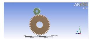
modeling, allowing for flexible design adjustments. Additionally, CATIA's product design module ensures precise assembly placement, contributing to the seamless depictionoftheassemblyinthecontextofthisstudy.
Figure 5 depicts the prescribed boundary conditions for the gear and pinion assembly. Notably, the gear's boundary conditions should facilitate exclusive rotation arounditsaxisandbesupportedbyafrictionlesshub.
Figure 2 depicts the bonded contact established between mating surfaces, seamlessly integrated into ANSYS throughautomaticinterpretationofthecontactdefinitions from CATIA. This integration is facilitated by the accurate alignment of mating surfaces within CATIA, ensuring a seamless transition of contact definitions to the ANSYS environment.
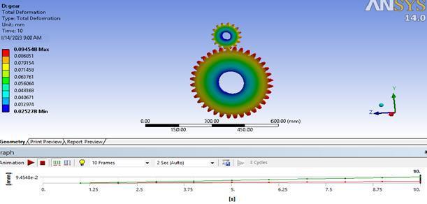
In Figure 5.10, the deformation of the pinion and gear assembly, taking into account the applied torque on the pinion, is presented. The analysis reveals that the overall maximum deformation is 0.08 mm, which is insignificant inrelationtothegearmeshrequirements.
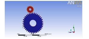

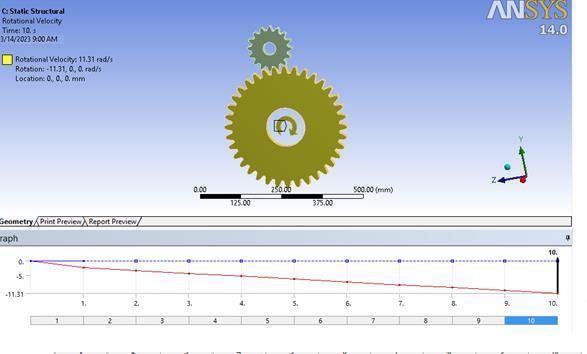
In Figure 4, it can be observed that the gear is imparted withaclockwiserotationalvelocityof11.31m/s.

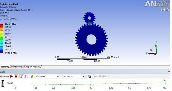
InFigure5.11,theEquivalentVonMisesstressofthegear andpinionassembly,taking intoconsiderationthetorque applied to the pinion, is depicted as 124.41 N/mm². This valueslightlydeviatesfromthenumericallyobtaineddata of 139.1 N/mm², potentially attributed to environmental influences such as gear friction and the assumption of a frictionlesssupportatthehub.
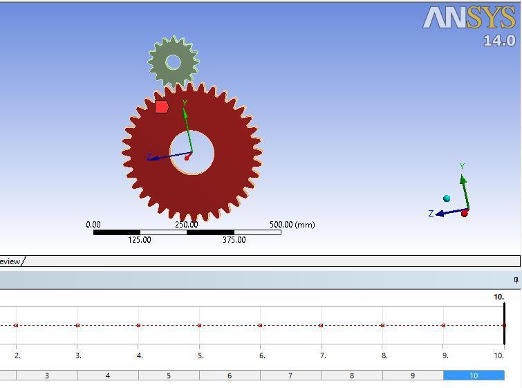
Figure 5.5 illustrates the gear under specific boundary conditions, enabling its movement along the y and z directionswhilerestrictingmotionalongthexdirection.
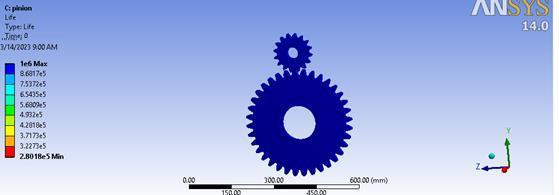
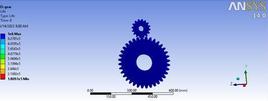
InFigure5.12,thelongevityofthegear-pinionassemblyis illustrated, taking into account the applied torque on the pinion. This depiction portrays the fatigue life or durability of the meshing gears within the specified
boundaryconditions,determinedtobewithintherangeof 106cycles.
enablestheevaluationofhowtorqueaffectsthedurability of the gear system. Notably, higher torque levels contributetoheightenedstressandanelevatedlikelihood offatiguefailure.
In Figure 5.14, the deformation of the pinion and gear assembly resulting from the applied torque on the gear is presented. The analysis indicates that the overall maximum deformation is 0.09 mm, a value of minimal significance in relation to the requirements of the gear mesh.
5. Conclusion:
The stress obtained numerically for the pinion is 139.1 N/mm², while the software-based solution yields 124.41 N/mm², demonstrating a proximity of approximately 89.5%tothenumericalvalue.
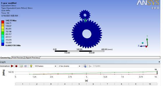
1. For the gear, the stress calculated numerically is 160.5 N/mm², whereas the software-based solution results in 142.5 N/mm², exhibiting an approximate 88.79% convergence with the numericaloutcome.
2. The design proves safe with nearly negligible deformation.
3. Numerically determined fatigue life falls within therangeof107cycles,apredictioncorroborated by software simulation which estimates fatigue lifeataround106cycles.
InFigure5.15,theEquivalentVonMisesstressofthegear and pinion assembly, taking into account the torque applied to the gear, is showcased as 142.55 N/mm². This value is slightly lower than the numerically obtained data of166.556N/mm²,andthisdisparitycanbeattributedto environmental factors such as gear friction and the assumptionofafrictionlesssupportatthehub.
4. Deviationsfromthenumericaldatamayarisedue to factors such as the omission of friction in our gear assembly simulation. Additionally, while we utilizedafinemeshsize,furtherrefinementcould potentiallyyieldimprovedresults.
References:
[1]Seok-ChulHwanga, Jin-HwanLee b, Dong-Hyung Lee c, Seung-Ho Hana, Kwon- HeeLee,Contact stress analysis for a pair of mating gears, Mathematical and Computer Modelling57(2013)40–49
[2] Prashant Kumar Singh , Siddhartha, Akant Kumar Singh An investigation on the thermal and wear behavior of polymer based spur gears, Tribology International 118 (2018)264–272
Figure16,depictedasFigure5.16,portraysthefatiguelife or endurance of the gears under varying boundary conditions, with a particular focus on the influence of torque applied to the gears. The figure illustrates the quantityofcycles(fallingwithintherangeof10^6cycles) that the gears can sustain before encountering fatigueinduced failure. A careful examination of Figure 5.16
[3] R. PrabhuSekar and R. Sathishkumar, Enhancement of Wear Resistance on Norma Contact Ratio Spur Gear Pairs throughNonStandardGears,Wear.

[4]I.S.Al-Tubi,H.Long,J.Zhang,B.Shaw,Experimentaland analytical study of gear micropitting initiation and

propagation under varying loading conditions, Wear328 329(2015)8–16
[5] Xiang Daia, Christopher G. Cooleyb, Robert G. Parkera,Dynamic tooth root strains and experimental correlations in spur gear pairs, Mechanism and Machine Theory101(2016)60–74
[6] Shuting Li et al. Centrifugal load and its effects on bending strength and contact strength of a high speed thin-walled spur gear with offset web, Mechanism and MachineTheory43(2008)217–239
[7] Xihui Liang, Hongsheng Zhang, LibinLiu , MingJ.Zuo, The influence of tooth pitting on the mesh stiffness of a pair of external spur gears, Mechanism and MachineTheory106(2016)1–15
[8]T.Osman,Ph.Velexetal,Amodelforthesimulationof theinteractionsbetweendynamic toothloadsandcontact fatigue in spur gears, Tribology International 46 (2012) 84–96

[9] Santosh S. Patil, Saravanan Karuppanan, Ivana Atanasovska ,Experimental measurement of strain and stress state at the contacting helical gear pairs, Measurement82(2016)313–322
[10]AnkurSaxena,Anand Parey,ManojCooksey,Effectof shaft misalignment and friction force on time varying mesh stiffness of spur gear pair, Engineering Failure Analysis49(2015)79–91
[11] Miriam B. Sánchez, Miguel Pleguezuelos, José I. Pedrero,Calculationoftoothbendingstrengthandsurface durability of internal spur gear drives, Mechanism and MachineTheory95(2016)102–113
[12] Wu Jiateng, Yang Yu, Yang Xingkai, Cheng Junsheng, Fault feature analysis of cracked gear based on LOD and analytical-FE method, Mechanical Systems and Signal Processing98(2018)951–967
