DESIGN AND ANALYSIS OF LINE FEED CIRCULAR MICROSTRIP PATCH ANTENNA WITHOUT SLOT AND WITH LOADED S- SLOT FOR C AND XBANDS APPLICATION.
1 Research Scholar, Department of Physics and Electronics. Dr. RammanohaLohiaAvadh University Ayodhya.U.P, India.
2 Prof. K.K Verma Pofessor, Department of Physics and Electronics Dr. Rammanohar Lohia University Ayodhya. U.P, India
Abstract - This paper presents design, simulation and comparative study between un slotted andS-slottedinset line feed circular micro strip patch antenna .The unslotted circular patch antenna resonated at 9.7 GHz with return loss-10.08dB but S-slotted antenna exhibited resonance at 8.9GHz frequency with return loss11.123dB, covering C-Band and X-Band. The design and simulation process has been carried out through C.S.T. Microwave Studio. The characteristic properties of antenna such as bandwidth, return loss, VSWR have been investigated, analyzed and compared for both
Key Words: Un- slotted circular micro strip patch antenna, S-slotted circular micro strip patch antenna, CST
1. INTRODUCTION
Anantennaisthebasicandkeyelementofallkindsofthe wirelessnetworkingandcommunication.Accordingtothe IEEE standard, “Antenna is assumed as a device of transmissionandreceptionofradiowaves”[2].Recently,the evolutioninthewirelesssystemleadstoalotofinnovations in the microstrip patch antenna.Microstrip patch antenna technologyhas achieved its quick development in the late 1970s.Bytheearly1980sfundamentalmicrostripantenna componentwerefairlywellestablishedintermsofdesign and modeling. The microstrip patch antenna has more advantages over other microwave antennas in the area of portability because of its low profile, low cost fabrication, light weight, easy to install and integrate with feeding networks. Due to simplicity and compatibility microstrip patch antennas are being used at lage scale in various microwave frequency spectrum to serve commercial and technological purposes [2-5]. But with these fetures and quantummeritspatchantennasfacessomedrawbackslike narrowbandwidth(NBD),lowefficiencyandlowgain[2-4]. Therefore these antennas have very narrow band width characteristicsasitlimitsthefrequencyrangeoverwhich theantennacan perform[2].However,thebandwidthand thesizeofanantennaare eciprocaland self-contradictory properties, that is in ,improvement of one of the characteristicsnormallyresultsindegradationoftheother.
Asaresult,itfetchedtheattentionofinventors, investors andscientists topromptandmotivatemore researchinto improvements in related fields. Researchers have made mutifold efforts to overcome these challenges through various mechanisms. One ,out of these mechanism, to achieve desirable resonant frequency and improved band width,ismodificationoninfigurationofdifferentshapesof patch likeS-shape, L-shape, E-shape with various dimensions[5-7]. Another mechanism to improve band widthismodificationintheshapeofpatchbycuttingslotsin it,likeU-Slot,V-Slot,E-SlotandS-Slot[9-11].Thuspatchand slotaretwodifferent parametersandconstants affectingas a hole performanceofnan antenna fairly[11].Therefore, keepingthesemodificationsinview,patchoftheproposed antennasisslottedproperlyinS-shape,whichhaveoffered anappreciableincreaseinbandwidthovermorethan>400 MHz.Insetlinefeedcircularpatchantennawith S-shaped slot consist of S-slotted circula patch, supported on a groundeddielectricFR-4sheetof thicknessh=1.6mm and dielectricconstant4.3[13].Themainpurposeandobjectof this paper is tocompare and analyze of band width (WB) characteristics properties under -10 dB return loss at resonantfrequencies8.9GHzandotherscharacteristicssuch as voltage standing wave ratio (VSWR), directivity, gain , efficiency etc. of the proposedantennas whichhave been incorporatedintotwoquietlydifferentshapesofS-slot and withoutslot.
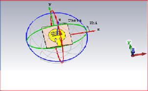
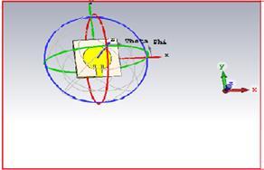
Forlinefeedcircularmicrostrippatchantenna,theheightof substrateFR-4is1.6mmandrelativepermittivityεris4.3.The innerandouterradiiofpatchareri=0.0mmandro=8.0mm .ThelengthandwidthofsubstrateFR-4areL=58.32mmand W=75.2mm.respectively.Perspectiveviewsoftheproposed antennasareshowninfig-1

Antenna Dimensions
LFCP PatchInnerradius ri =0mm Copper
PatchOuterradius ro=8.8mm
Patchthickness t=0.036mm
Substrateheight h=1.6mm

Substratewidth W=75.2mm
Slot-S
Substratelength L=58.32mm FR-4
Groundlength L=58.32mm
Groundthickness t=0.036mm
Groundwidth W=75.2mm copper
Feedlinewidth Wf =3.261mm
Feedlinelength lf =20.0mm
Verticalexpansionof letter-S 5mm
Horizontalexpansion ofletter-S 5mm
Thicknessofstrip 0.5mm
2. SIMULATIONS AND RESULTS:
Air
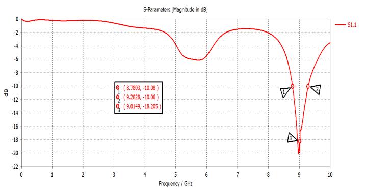
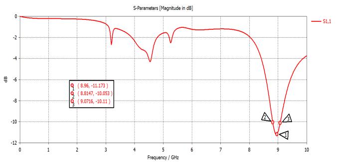
2.1 RETURN LOSS: After designing the antennas by CSTMWS 2018, simulation function has been carried out. Plots for simulated return loss of circular patch antenna withoutslotandwithslot-Shavebeenshowninfig-2andfg3respectively.Magnitudeofreflectioncoefficienthavebeen foundtobe-10.05dBat8.78GHzofcircularmicrostrippatch antenna without slot and -11.1dB at 8.9GHz of circular microstrip patch antenna with slot –S. At -10dB the bandwidth has been found 26.7MHz which covers 29.3% bandwidth at resonant frequency8.7GHz for circular micostrippatchantennawithoutslot.Whereasat-10dBthe bandwidthhasbeenfoundtobe26.9MHzwhichcovers30% bandwidth at resonant fequency8.9GHz for circular microstrippatchantennawithslot-S.
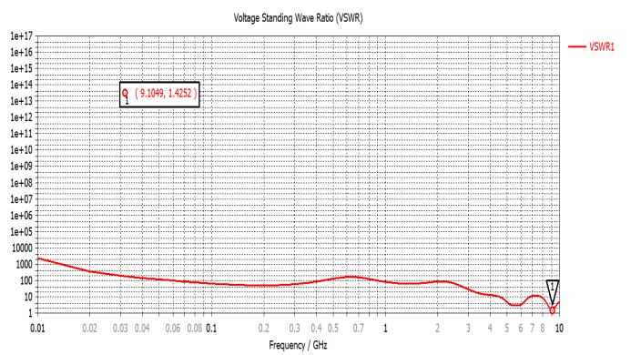
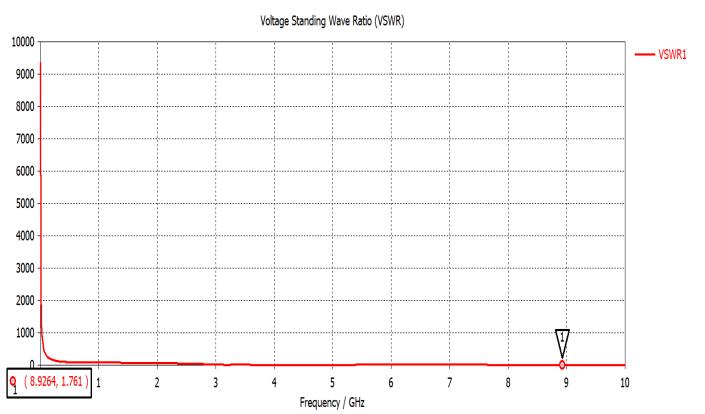
2.2: VSWR: Plots for VSWR of line feed circular microstip patch antenna without slot and with S- shaped slot have been shown in fig-4 and fig-5 respectively. Magnitude of VSWR for line feed circular microstrip patch antenna is found as 1.761 at resonant frequency 8.9GHz which is in goodagreementandveryclosetoanidealvalueof1foran impedance matching. Whereas for line feed circular microstrip patch antenna with S-shaped slot it has been foundtobe1.4252atresonantfrequency9.10GHz.Whichis in good agreement and close to an ideal value of 1 for impedancematchingalso?

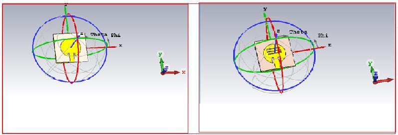
2.3 FARFIELD DIRECTIVITY : Polar plots for line feed circularmicrostrippatchantennawithoutslotandwithSshaped slot are shown in fig-6. For line feed circular microstrippatchantennawithoutslot,Mainlobemagnitude isaround-0.708dBiandAngularwidthisobtainedas51.4 degree whereas for line feed circular microstrip patch antennawithS-shapedslotmainlobemagnitudeis-4.55dBi andAngularwidthisobtainedas89.6degree.
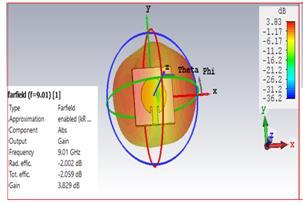
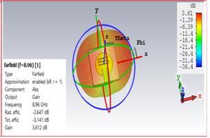
2.4 RADIATION PATERN : The 3D-plots for radiation pattern of gain for line feed circular microstrrip patch antennawithoutslotandwithS-shapedslotareshowninfig 7.For line feed circular microstrip patch antenna without slot,gainis3.829dBandradiationefficiencyisobtainedas 97.23% nearlyat resonantfrequency8.9 GHzand for line feed circular microstrip patch antenna with S-slot gain is 3.612dB and radiation efficiency is 84.27% at resonant frequency9.1GHz

Fromabovetable,itiswellvividthatS-Shapeslottedinset line feed hexagonal microstrip patch antenna has overall better results than un- slotted inset feed line circular microstrippatchantenna.Morenegativevalueofreturnloss gives the better results. Hence S-Shape slotted circular microstrippatchantennashowbetterresultsincomparison toun- slotted circularmicrostrip patchantenna Lessthan value 2 and near to 1, better is the VSWR. The S-slotted antennashowsaslightlyhigherresonantfrequency,better return loss, wider bandwidth, lower VSWR, and higher directivitycomparedtotheun-slottedantenna.However,the un-slotted antenna exhibits higher gain, better radiation efficiency,andanarrowermainlobewithalowermainlobe magnitude. The specific antenna design and performance goalswilldeterminewhichtypeofantennaismoresuitable foraparticularapplication.
3. Conclusion
Thecomparisonbetweenun-slottedandS-slottedcircular microstrip patch antenna is done on the expence of simulation results obtained from CSTMW Studio. It, therefore,concludedthat boththeantennasconfiguration show good results in view of Returnloss ,VSWR, Gain and RadiationefficiencyforCandXbandsapplications.However, inviewofReturnloss,Bandwidth,VSWRandGain,S-Shape slotted circular microstrip patch antenna shows better performance,whereasun-slottedcircularmicrostrippatch antenna shows better performance in view of main lobe directionandradiationpattern.
REFERENCES
[1] M.James, J.R. and Hall, P.S.,”Handbook of Microstrip Antenna,”PeterPeregrinus,Vol.2,1989.
[2] ConstantineA.Balanis,”AntennaTheory:Analysisand Design,“JohnWiley&Sons,3rdEdition,2005
[3]Garg,R.P.Bahartia,andA.Ittipiboon,”MicrostripAntenna DesignHandbook,”ArtechHouse,Boston,London,2001.
[4] Garg, Ramesh, “An improved formula for the resonant frequencies of the triangular microstrip patch antenna, “AntennaandPropagation,IEEETransactions,Vol.36Issue: 4,1988
[5]IndrasenSingh et al,”Microstrip PatchAntenna and its Application:asurvey,”Int.J.Comp.Tech..Appl,Vol.2,pp.15951599,2001.

[6]MeladM.Olaimata&NihadI.Diba,”Improvedformulafor the resonant frequencies of triangular microstrip patch antenna, “International Journal of Electronics, Vol.98, Issue3.2011
[7]RazinAhmadandMd.FokhrulIslam,”ModifiedE-Shaped MicostripPatchAntennaLoadedwithMetamaterialforKu Band”Published in Electrical Engineering Journal,Vol.5,No.6,pp.1459-1465,August2014
[8]Rafi,G.andL.Shafai,”Broadband microstrippatchantenna with V-slot,”IEEproc.Microwave Antennas and Propagation,Vol.151,435-440,2004
[9]RazinAhmad,andMd.FokhrulIslam,”SlottedMicrostrip Patch Antenna for Multiband Application “Published in International Electrical Engineering Journal(IEEJ),Vol.5(2014)No.3,pp.1293-1299,April2014
[10]Lee,K.F.,etal.,\ExperimentalandSimulationstudiesof the coaxial fed U-Slot rectangular PatchAntenna,”IEEE Proceedings/Microwave Antennas Propagation,Vol.144,No.5,354-358,1997.
[11] Ramesh Garg, Prakash Bhartie,Inder Bahl,Apisak Ittipiboon,”Microstrip Antenna Design Handbook,”Artech HouseInc.Norwood,MA,2009,pp.1-68,253-316.0
[12]F-Yang.-X.Zhang.,X.Ye,andY.Rahmat-Samii,”wideband E-shaped patch antenna for wireless communication,”in IEEE trans. Antenna Propagation,Vol.49,no.7,pp.10941100,July2001
[13]JigerM.Patel,ShobhitK.Patel,FalgunN.Thakkar,”Design of S shaped multiband Microstrip patch antenna, ”Engineering(NUICONE)2012 Nirma University InternationalconferenceinIEEEAhmadabadISBN:978-146731720-7.
[14] Tanish Narang; shubhangi jain; “Microstrip Patch Antenna-A historical perspective of the development” , conference on advance in Communication and control system2013(CAC2S2013)
[15] Z.Ying, “Antennas in cellular phones for mobile communications” in Proceeding of the IEEE, Vol.No. 100 pp2286-2296,July2012

BIOGRAPHIES
Mr.MaheshNarayanborn on2nd July of 1965. He obtained his Master’sDegree(M.Sc.)inPhysics (solidstatephysics)fromBanaras HinduUniversity(BHU),Varanasi, U.P, India. He is Graduate in PMS group with B.Sc. (HONS) Physics, from the same University. He has more than 32 yearsof experience inteachingofdifferentbranchesof appliedscienceandespeciallyinphysics.Hejoinedasa lecturerinPhysicsinNovemberof1992andpresentlyhe is working as a senior Lecturer of Physics in SSV Inter College,FaizabadU.P,India.Heisauthorofseveralbooks ofphysicsnumericalandpractical.Bydintofhardwork and devotion to duty, he has acquired many awards / honors.
Prof K.K.VermahasbeenawardeddegreeofPh.D.from B.H.U.Varanasi.HejoinedasalecturerinElectronicsin November1993,DepartmentofPhysicsandElectronics, Dr.RamManoharLohia AvadhUniversity,Faizabad.U.P. India.Presentlyheisworkingasaprofessorinthesame department
