Design And Analysis of Different Artificial Human Hip Stems Based on Fenestrations Using PEEK Material
Mr. Rohith. N1,
Dr. H. C. Chittappa21M. Tech Student, Department of Mechanical Engineering, University Visvesvaraya College of Engineering, Bangalore, Karnataka, India.
2Professor, Department of Mechanical Engineering, University Visvesvaraya College of Engineering, Bangalore, Karnataka, India.
Abstract - The Hip joint is a primary joint which provides stability to the human body. These joints will be replaced by the implants during hip replacement procedures due to wear and strain brought on by ageing and other factors. Hip joint prostheses are structural parts that still struggle with complex issues including the interaction of the hip stem's physical and biological characteristics with the human femur bone. On the commercial market, there are numerous varieties of artificial hip joints. The needs of the patients can be accommodated by choosing from a variety of materials and designs. One of them is the hip stem design with fenestrations. Titanium and stainless steel are the materials that are frequently utilised in hip joint replacement. The design and analysis of complete joint replacements and other orthopaedic devices have benefited from the use of the finite element approach in orthopaedic biomechanics.
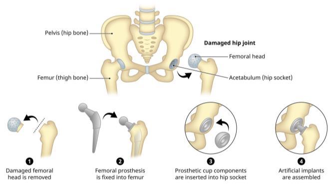
In this work, three different types of hip stems were considered viz., hip stem with out fenestration, hip stem with bigloop fenestration and hip stem with slot fenestration were modeled using SOLIDWORKS 2018 by Dassault Systems and these hip stems were analyzed for the stress–strain distribution and deformation over the hip stem prosthesis under different loading conditions like, standing, walking, jumping and running for this we used two different materials Polyether-ether-ketone (PEEK) and Ti-6Al-4V using renowned tool ANSYS Workbench 2022 R2 version to produce the hip stem with the best design and material available.
Key Words: Finite Element Method, Biomaterials, Hip implant, Artificial hip joint, PEEK.

1. INTRODUCTION
A biomaterial is a material that have been produced to interact with living systems for therapaeutic (treating, improving, fixing, or changing a tissue function of the body) either diagnostic purpose. Bio-materials has been a field of study for nearly 50 years. Bio-implants, which includeporousboneimplants,dentalimplants,prostheses, wearable biosensors, and drug delivery devices, are all implants used in medical or clinical therapy. Typically, theyareplacedwithinthebodyofapersonformorethan 30days.Theyintegratewiththehumanbody,thequalities
of materials, and the intactness of bio-implants to fix, sustain, recreate, either to improve the function of the humantissues.
1.1 Total Hip Replacement
Hipjointreplacementusingartificialreplacementsurgery needs to be performed for patients with permanent hip joint damage due to, aging, necrosis, osteoarthritis, osteoporosis or accidents. Many patients with hip joint disease have difficulties carrying out for daily activities; thus, hip replacement surgery has become a standard method.THRiscalledas“OperationofCentury”becauseit has revolutionised the treatment of a patient with advanced hip disorders. THR involves exchange of the morbid hip with a hip implant referred to as prosthesis, that is employed to transferring the load from socket to the leg bone by implanting a hip stem into the latter. Ideally, the stem area of a hip implant thought to be fully contact with the surrounding femure cortical bone to attain stable fixation during a THR. The hip implant is additionally responsible for getting the physiological load from the hip stem and transfers some amount of it to the surrounding tissues. These are the major surgical procedures, that are solely undertaken once the disease hasproceededtothestagewherenodifferenttreatmentis possible the aim is to alleviate pain and improve mobility
2. LITERATURE REVIEW

Solehuddin bin Shuib et al. Hip implants are prosthetic jointsmadeofmetalsliketitaniumalloyorstainlesssteel. They are carried in place by lengthy stems that protrude deep into the femur canal. When a human hip joint withstandsabiologicalinjury,itistypicallyused.Analysis alsorevealsayearlyriseinthenumberofpeoplewhoget thistypeofsurgery,especiallythosewhoareolderandfall into the 65+ age group. The objective of this study is to research hip implant advancements and to suggest a designthatfullysatisfiestherequirementsfordesigninga hip implant. Hip implants must take into consideration a variety of factors, including stiffness, implant characteristics, and implant size. Materials are among the most essential design considerations for a hip implant since they have a direct impact on the implant's stiffness. Titanium and stainless steel are the commonly used materials[2]
Kelechukwu Onuoha et al. The process of THR is eminent. By reducing pain and functional impairment, THR enhances the quality of life for persons with moderatetoserioushiparthritis.Inthisanalysis,onlyhip osteoarthritis patients were included. It was simple to identify osteoarthritis as an indication for the surgery becauseresearchalsoshownthatarthritiswasacommon reason for THR. 71.4 % of the patients in this work were foundtobeolderthan50years[3]
Manuel Guzman et al. Thefemoralheadandthehipstem are the two primary parts of the prosthesis utilized in THR. SS 316L, Ti alloys (Ti-6Al-4V and TMZF), and Co-Cr alloys are the most commonly utilized metal alloys for these components, despite the fact that they are prone to loose particles. These materials after implanted, plays a crucialroleinthedistributionofstressandstrainbecause their high elasticity modulus which is greater than that of human bone. The requirements for a hip implant’s design are complicated because there are so many factors to be taken into an account, including the patient’s age, the geometry of the implant, the bone structure, and the biocompatibility of the material. All of these factors have animpactonhow muchstressandstraintheimplant will experience. One way to avoid future complications, including aseptic loosening or implant fracture, is to modify the shape of an existing prosthesis or use an ideal biomaterial[4].
Anthony L. Sabatini et al. This article reevaluated a number of hip stems. For all the stems, FE Analysis was carried out using different cross-sections. In addition to recording the displacement, von-Misses stress comparisons were performed for each of the stems at the predetermined places. The analysis was conducted using three materials: Ti-6Al-4V, SS316L, and Cr-Co-Mo. Ti-6Al4V showed less stress than the other two materials. The
circular and eliptical cross-sections shaped even distribution of stresses throughout the length of the hip stemthantheothercross-sectionsviz.;trapezoidandoval. This analysis could clarify the scenarios that should be avoided for hip implants that need stress shielding. For total hip replacements, additional anatomical designs are required[5]
M. Paglia et al. PEEK is a polyaromatic semi-crystalline thermoplastic polymer which was first developed for engineeringapplicationsbyVictrexPLCintheearly1980s. It was initially made available for industrial use in the production of bearings, compressor plate valves, cable insulation,turbine blades,pistonparts,andaircraft.PEEK is a polymer that is organic and colourless that is a member of the PAEK (polyaryl-ether-ketone) family. A single monomer makes it a homopolymer. This thermoplastic semi-crystalline polymer retains its outstandingchemical andmechanical characteristicseven at elevated temperature. PEEK is stable at high temperatures due to its chemical compositions and structure, which facilitates simple manufacturing of PEEK implant components. When subjected to heat sterilising processes, PEEK is resistant to degradation. Due to its excellent thermal characteristics, superior wear resistance, great processability, inertness, corrosion resistance, high strength, and elastic modulus, PEEK is widely employed in both medical and engineering fields. Infact,ithasanelasticmodulusthatisidenticaltohuman bone, indicating uniform stress distribution to the tissues around it. PEEK is a non-toxic, non-mutagenic substance that is extremely compatible with the tissues in its surrounding environment. As a result, it may be the perfectreplacementforthosewhoareallergictotitanium and other metals. PEEK has a more aesthetically pleasing appearance and doesn't have a metallic toneit seems beigewithahintofgrey[6]
Jiaqi Zhang et al. Skull deformities are treated through cranioplasty, which involves raising the scalp and reshapingtheskullwiththeoriginalpiece,titaniummesh, orsolidbiomaterial.Medicalpractitionersareincreasingly using additive manufacturing technology, often known as 3D printing, to create specialized, replicas of tissues, organs, and bones, providing a viable solution with ideal anatomic fitting in the individual and skeletal reconstruction. Here, we analyze a patient from 15 years agothathadtitaniummeshcranioplasty.Thelefteyebrow arch was weakened by the titanium mesh's unsightly appearance,whichalsocausedasinustracttodevelop.An additively produced polyether ether ketone (PEEK) skull implantwasusedduringcranioplasty.PEEKskullimplants havebeeninsertedsuccessfullywithoutanyissues.Toour information, this is the 1st reported case of direct use of fused filament fabrication (FFF) fabricated PEEK implant forcranial repair. TheFFF-printedPEEKcustomizedskull implant can possess simultaneously with adjustable
material thickness and more complex structure, tunable mechanical properties,andlowprocessing cost compared totraditionalmanufacturingprocesses[7].

3. PROBLEM IDENTIFICATION
At present in medical field Titanium alloys, Stainless steel and Co-Cr alloy materials are been used for the artificial human hip stems. These materials have good mechanical and physical properties, they are very strong in nature. But the stiffness / elastic modulus of these materials are too much high when compared with the bone properties, due to this when the load applied on the hip joint the maximum load will be on the implant. When hip implant carriesmoreloadthanthefemurbonethentherewillbea wearbetweenboneandtheimplantthiseffectiscalledas shield stressing, by this it gets loosen very quickly before itslifespan.Also,weightoftheimplantismore.Increases in bone porosity. Decrease in bone mass. There will be a magnetismeffectandanode-cathodereactions.
4. OBJECTIVES
To design for development of an artificial human hip stems based on fenestration using CAD modellingsoftwarei.e.,SOLIDWORKS2018.
To perform FEA for all different types of fenestrated artificial human hip stems for Polyether–ether–ketone (PEEK) and Ti-6Al-4V materials under different conditions such as standing, walking, jumping and running using ANSYSWorkbench2022R2.
ResultsofthethreedifferenthipstemswithPEEK andTi-6Al-4Vmaterialswillbecomparedandone ofthebestwillbesuggested.
To reduce the weight of human hip implant by using PEEK material instead of Titanium alloys, StainlesssteelandCo-Cralloy.
Toimprovethestrength,corrosionresistanceand wear resistance of the hip stem by this stress shieldingcanbeprevented.
5. METHODOLOGY
6. DESIGN AND ANALYSIS OF HIP STEMS
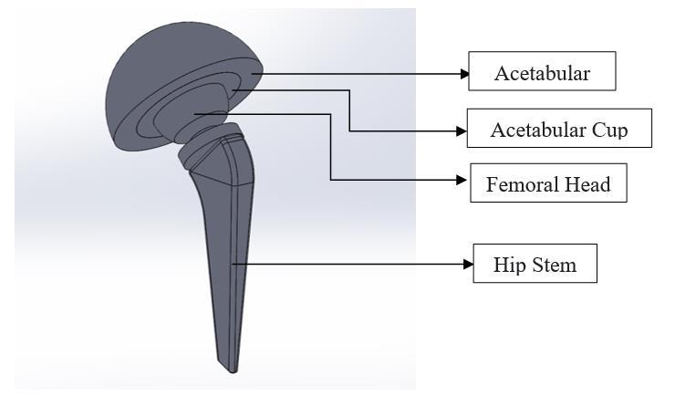
The CAD models have to be created in the computer environment.HerewedesignedaHipReplacementofeach different parts, the dimensions of each part is collected frompreviousrecord.SOLIDWORKS2018havebeenused inthemodelingprocess.
6.1 Different types of fenestration designs
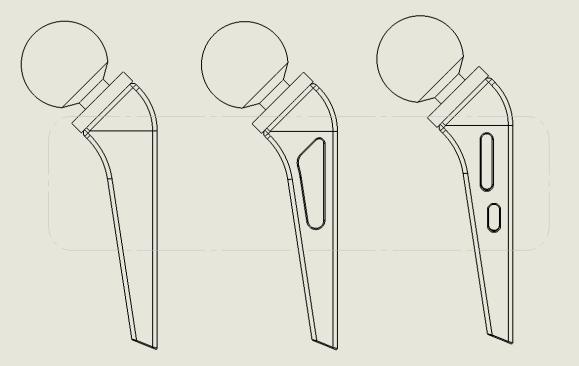
Fig. 4 Typesoffenestration
For hip replacement, artificial hip joints come in a variety of designs and shapes. Three different hip joint designs were used in this study, as shown in Fig. 4: a hip stem without fenestration, a hip stem with a big loop fenestration, and a hip stem with a slot fenestration [8]. The onlydifferenceindimensions wasfenestration. PEEK and Ti-6Al-4V were both employed as the materials. Materials were chosen for their high biocompatibility, durability,resistancetowearandcorrosion,andstrength. The material was thought to be uniform, isotropic, and linearlyelastic.
7. RESULTS AND DISCUSSION
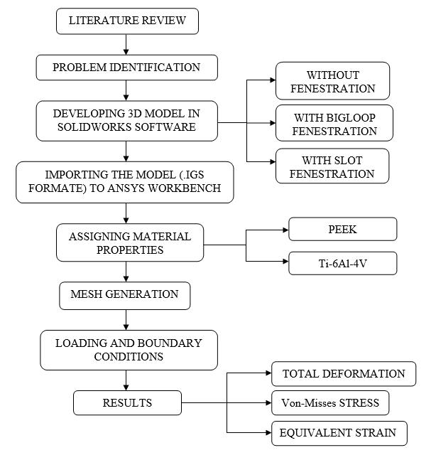
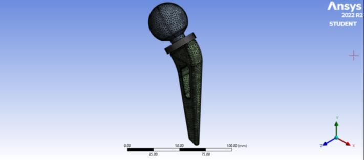
The final model was assembled in SOLIDWORKS and imported to ANSYS Workbench software in .IGS format and the analysis is carried out in Static structural. So in thisprojectwearegoingto considerthreedifferenttypes ofhipstemdesignsnamely,hipstemwithoutfenestration, hipstemwithbigloopfenestrationandhipstemwithslot fenestration. Further these hip stems should be analyzed for different loading conditions like, standing, walking, jumpingandrunning.ThencomparingtheresultsofPEEK materialwithcommonlyusedTitaniumbasedalloyTi-6Al4V for all these hip stems. The mechanical property of thesematerialsisgivenbelowTable1.
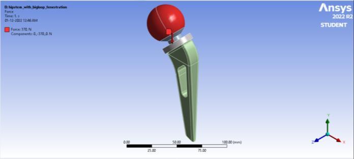
considered according to Aftab S et al. [10] on a patient who weighs 75 Kg, withan agegroup ofaround 35years. Duetothesymmetryofthehumanbody,whenapersonis standing, their weight will be distributed evenly between their two legs. For this reason, the weight was divided in half and boundary conditions were applied to the finite element model. The analysis was performed under the assumptionthatthesubjectwasstandingnormally,witha load of 370 N applied to the head of the femur at the hip joint and the hip stem fixed when in contact with the femoral bone. Similar to this, the hip stem was examined under a variety of situations derived from various human everydayactivities,suchasjumping,wherea forceof750 Nactingononelegwasapplied,forwalkinganadditional 800 N was applied, and running, where a load of 1463 N wasapplied.AlsoshownintheTable2.
Wearegoingtousesomedifferentactivitieslikestanding, walking, etc. So the stress analysis on a hip prosthesis during various patient activities, such as standing, walking, jumping as well as in running. These loads are

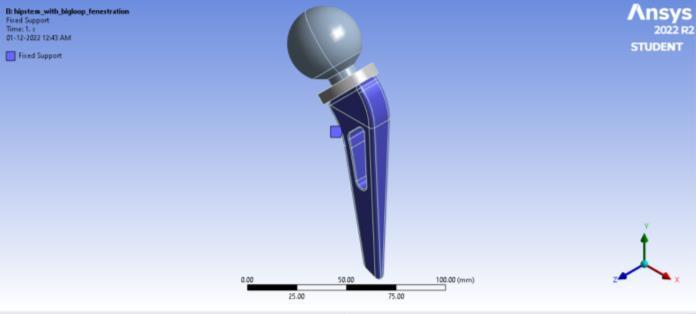
The below Fig. 6 indicates the fixed/support condition to thehipimplant.

6 Supportcondition
TheFig.7showstheapplyingofloadingconditionswhich are mentioned in the Table 2. The force of 370 N magnitude is applied along the -y direction as shown in thefollowingfigure.
Fig. 7 Applyingtheload


7.1 Computational Results
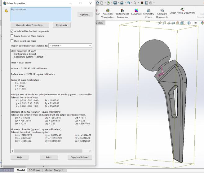
7.1.1 Masses of the different types of fenestrated hip stems
These below mentioned masses are taken from the SOLIDWORKS software by applying the material propertiesofthePEEKand Ti-6Al-4Vforthedifferenthip stemdesigns.
7.1.2 Standing condition (370 N)
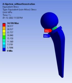
TheFig.10(a)referstoVon-misessstressproducedinthe hip stem without fenestration under standing condition when PEEK material is applied to the hip stem which is 34.106 MPa, which is similar for the remaining fenestrations.
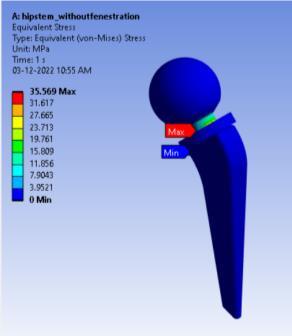
TheFig.10(b)referstoVon-misessstressproducedinthe hip stem without fenestration under standing condition when Ti-6Al-4V material is applied to the hip stem which is 35.569 MPa, which is similar for the remaining fenestrations.
From Fig. 11 the von-misses stress of hip stem with slot fenestration for PEEK material is least when compared to othersinstandingcondition.
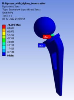
TheFig.12(a)referstoVon-misessstressproducedinthe with bigloop fenestration under walking condition when PEEK material is applied to the hip stem which is 78.393 MPa whichissimilarfortheremainingfenestrations.
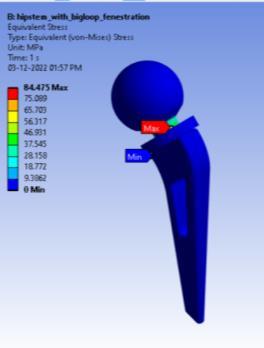
TheFig.12(b)referstoVon-misessstressproducedinthe hip stem with bigloop fenestration under walking condition when Ti-6Al-4V material is applied to the hip stem which is 84.475 MPa which is similar for the remainingfenestrations.
From Fig. 13 the von-misses stress of hip stem with slot fenestrationforPEEKmaterialisleast,whencomparedto othersinwalkingcondition.
7.1.4 Jumping condition (750 N)


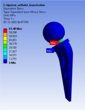
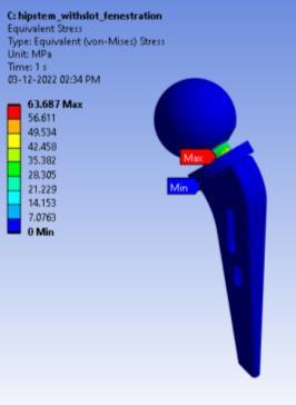
During jumping with the both legs 750 N load will be applied on one leg. The Fig 14(a) refers to Von-misess stress produced in the hip stem with slot fenestratation when PEEK material is applied to the hip stem which is 63.687 MPa, which is similar for the remaining fenestrations.
TheFig.14(b)referstoVon-misessstressproducedinthe hipstemwithslotfenestratationwhenTi-6Al-4Vmaterial is applied to the hip stem which is 65.48 MPa, which is similarfortheremainingfenestrations.

From Fig. 15 the von-misses stress of hip stem with slot fenestrationforPEEKmaterialisleast,whencomparedto othersjumpingcondition.
7.1.5 Running condition (1463 N)


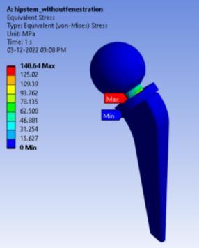
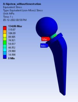
TheFig.16(a)referstoVon-misessstressproducedinthe hip stem without fenestration under running condition when PEEK material is applied to the hip stem which is 134.86 MPa, which is similar for the remaining fenestrations.
TheFig.16(b)referstoVon-misessstressproducedinthe hip stem without fenestration under jumping condition when Ti-6Al-4V material is applied to the hip stem which is 140.64 MPa, which is similar for the remaining fenestrations.

From Fig. 17 the von-misses stress of hip stem with slot fenestrationforPEEKmaterialisleast,whencomparedto othersinrunningcondition.
8. CONCLUSION
In this work, three hip stem designs, namely without fenestration, with bigloop fenestration and with slot fenestration designs were modeled. For all designs, two materials PEEK and Ti-6Al-4V was used. PEEK is used because it as the similar stiffness as human femur bone anditasgoodwearproperties,lowmoistabsorption,low co-efficient of friction etc. All of these designs, which use materials with various physical properties, will be put through the rigours of daily activities like standing, walking, jumping, and running. Static structural analysis was carried out using ANSYS Workbench with the application of the loading boundary condition as per the work by Aftab S. et al. All three designs were found to suggestlowerstresslevelsthantheyieldstrength.Also,in these three designs for PEEK and Ti-6Al-4V materials underdifferentloadingconditions,theartificialhumanhip stem with slot fenestration for PEEK material has lesser Von-Missesstressunderalldifferentloadingconditionsas
mentioned above. Ti-6Al-4V has less deformation when comparedtoPEEKmaterialforallthedesignswhichwere modeledinthecurrentwork.Itisobservedthatforallthe designsunderdifferentloadingconditionsthevon-misses stress is almost similar for PEEK and Ti-6Al-4V material. Also,weightofthePEEKmaterialislesserthantheTi-6Al4V. So, PEEK material with slot fenestration can be suggested.
REFERENCES
[1] L. Guo et al., “On the design evolution of hip implants:Areview,” Materials and Design,vol.216. Elsevier Ltd, Apr. 01, 2022. doi: 10.1016/j.matdes.2022.110552.
[2] S. Shuib, B. Sahari, A. Ahmed Shokri, and C. Soon Chai,“TheDesign ImprovementofHipImplantfor Total Hip Replacement (THR),” Jurnal Kejuruteraan, vol. 20, no. 1, pp. 107–113, Dec. 2008,doi:10.17576/jkukm-2008-20-10.
[3] “Clinical Outcomes Following Total Hip Replacement,” EAS Journal of Medicine and Surgery, vol. 4, no. 6, pp. 134
139, Jun. 2022, doi: 10.36349/easjms.2022.v04i06.003.
[4] M. Guzmán et al., “Finite Element Assessment of a HybridProposalforHipStem,fromaStandardized Base and Different Activities,” Applied Sciences (Switzerland), vol. 12, no. 16, Aug. 2022, doi: 10.3390/app12167963.
[5] A. L. Sabatini and T. Goswami, “Hip implants VII: Finite element analysis and optimization of crosssections,” Mater Des,vol.29,no.7,pp.1438–1446, 2008,doi:10.1016/j.matdes.2007.09.002.

[6] M. Paglia, M. Beretta, V. Quinzi, and S. Colombo, “PEEKpolymerinorthodontics:ascopingreview,” Eur J Paediatr Dent, vol. 23, no. 2, pp. 137–139, 2022,doi:10.23804/ejpd.2022.23.02.10.
[7] J. Zhang et al., “Additively manufactured polyether etherketone(PEEK)skullimplantasanalternative to titanium mesh in cranioplasty,” Int J Bioprint, vol.9,no.1,Nov.2022,doi:10.18063/ijb.v9i1.634.
[8] Ikhsan, A. R. Prabowo, J. M. Sohn, and J. Triyono, “Finite element analysis of different artificial hip stem designs based on fenestration under static loading,”in Procedia Structural Integrity,2020,vol. 27, pp. 101–108. doi: 10.1016/j.prostr.2020.07.014.
[9] Y. Jun and K. Choi, “Design of patient-specific hip implants based on the 3D geometry of the human femur,” Advances in Engineering Software, vol. 41,
no. 4, pp. 537–547, 2010, doi: 10.1016/j.advengsoft.2009.10.016.
[10] S.G.Aftab,A.Faisal,H.Hussain,B.Sreedhara,N.R. Babu, and B. A. Praveen, “Structural analysis of human femur bone to select an alternative compositematerial,” Mater Today Proc,vol.54,pp. 141–146, Jan. 2022, doi: 10.1016/j.matpr.2021.08.197.
