Multi Response surface optimization and desirability Function Approach for grinding material removal rate in Alloy Steel
Himanshu Vaishampayan 1 , Purushottam Sahu2 , Ghanshyam Dhanera 31Research Scholar BM College of Technology, Indore

2Professor and HOD BM College of Technology, Indore
3Professor BM College of Technology, Indore ***
Abstract - The provided information includes essential grinding parameters alongside real-world grinding outcomes, material removal principles, and feasible strategies for performance improvement. The analysis of the presented Material Removal Rate (MRR) figures confirms previous conclusions, revealing that the most significant influence on MRR values is the depth of cut at 92.06%, followed by cutting speed at 4.65%, and feed rate at 0.94%, which has a relatively minor impact. The ideal combination of input control parameters is A2B3C1. Calculating the grey relational grade using equation (7) yields a value of 0.4413. The results of the confirmation experiment for the response parameters are displayed in Table 5.9. Notably, Grey Relational Analysis (GRA) substantially enhances the experimental values of cutting speed (VC) in rpm, depth of cut in mm, and feed rate in mm/rev. The optimum material removal rate is 2.816 Gm./Min, achieved at (a) Cutting Speed in rpm (VC) A2 1900 rpm, (b) B3 0.06 mm cut depth, and (c) C1 0.04 mm/rev feed rate. The mixed desirability, represented by C1 D, is 0.93650. It's important to note that increasing the grinding contact width results in proportional increases in grinding forces and power. , Grey Relational Analysis (GRA)
Key Words Material Removal Rate (MRR), cutting speed (VC) in rpm, depth of cut in mm, and feed rate in mm/rev,
1. INTRODUCTION
Grinding is a machining process used to achieve precise and smooth surface finishes or to remove material from a workpiece to create the desired shape and dimension. It involves using abrasive particles to gradually wear away the material through friction and cutting action. Grinding is commonly used in various industries, such as manufacturing, automotive,aerospace,andelectronics,toproducecomponentswithhighprecisionandaccuracy.
Here'showgrindingworks:
1. Abrasive Material:Abrasivematerials,suchasgrindingwheels,belts,orstones,areusedinthegrindingprocess. Theseabrasivesaremadeupofhardandtoughparticlesthatarecapableofcuttingandremovingmaterial.
2. Workpiece and Grinding Wheel Interaction:Theworkpieceistheobjectbeingground,anditisheldsecurelyin placeonagrindingmachine.Thegrindingwheelorabrasivematerialisrotatedathighspeed,creatingacuttingor shearingactionwhenitcomesintocontactwiththeworkpiece.
3. Contact and Friction:Astherotatingabrasivecontactstheworkpiece,itcreatesfrictionandgeneratesheat.The abrasiveparticlescontinuouslyremovesmallchipsofmaterialfromtheworkpiece’ssurface.
4. Material Removal:Thecombinationofcuttingactionandabrasivewearresultsinmaterialbeingremovedfrom the workpiece. The grinding process gradually shapes the workpiece to the desired dimensions or provides the desiredsurfacefinish.
5. Coolant or Lubrication:Tocontroltheheatgeneratedduringgrindingandpreventdamagetotheworkpieceor grinding wheel, a coolant or lubricating fluid is often used. This fluid also helps to wash away the removed materialandkeepthegrindingsurfaceclean.
6. Precision and Finish: Grinding is capable of achieving extremely tight tolerances and smooth surface finishes that may not be achievable through other machining methods. This makes it suitable for applications where precisionandaestheticsarecrucial.
7. Types of Grinding: There are various typesof grinding processes, eachdesignedforspecific applications. Some commontypesincludesurfacegrinding,cylindricalgrinding,centerlessgrinding,andinternalgrinding.Eachtype usesspecializedgrindingmachinesandtechniquestoachievethedesiredresults.

Overall, grinding is a versatile and essential process used to produce parts with high accuracy, achieve smooth surfaces, removematerialfromtoughmaterials,andrefinetheshapesofworkpiecetomeetspecificrequirements.
1.2 Basic Surface and Cylindrical Grinding Processes
SurfaceGrindingProcess:
Surface grinding is a widely used abrasive machining process that involves grinding a flat or contoured surface of a workpiece using a rotating grinding wheel. The primary goal of surface grinding is to achieve a smooth and flat surface finishontheworkpiece.Here'sanoverviewofthebasicstepsinvolvedinthesurfacegrindingprocess:
1. Preparation: The workpiece is securely mounted on the grinding machine's worktable. The grinding wheel is chosen based on the material being worked on and the desired finish. The wheel is then dressed to ensure its propershapeandabrasivegrainexposure.
2. Grinding Operation: The grinding wheel rotates at high speed, and the worktable holding the workpiece moves backandforthbeneaththerotatingwheel.Asthewheelcontactstheworkpiecesurface,abrasiveparticlesonits surfacecutintoandremovesmalllayersofmaterial,creatingaflatandsmoothfinish.
3. Coolant Application: Coolant or lubricating fluid is typically applied during the grinding process to control heat buildup,washawaydebris,andimprovesurfacequality.
4. Finishing Passes: Depending on the desired surface finish and material removal requirements, multiple passes maybemadeover the workpiece.Eachpassremovesa thinlayerof material until thedesiredspecificationsare met.
5. InspectionandQualityCheck:Aftergrinding,theworkpieceisinspectedfordimensionalaccuracy,surfacefinish, andotherqualityparameterstoensureitmeetstherequiredspecifications.
CylindricalGrindingProcess:
Cylindrical grinding is another common abrasive machining process used to create cylindrical or tapered surfaces on a workpiece.Itis oftenusedtoproduceprecisecylindrical parts,suchasshafts,tubes,androds.Here'sanoverviewofthe basicstepsinvolvedinthecylindricalgrindingprocess:
1. Workpiece Setup: The cylindrical workpiece is mounted between centers on a cylindrical grinding machine. The workpiecemayberotatedbythemachineordrivenbyaseparatemotor.
2. Grinding Wheel Selection: A cylindrical grinding wheel is selected based on the workpiece material, size, and desiredfinish.Thewheelisdressedtotherequiredshapeandabrasivegrainexposure.
3. GrindingOperation:Thegrindingwheelrotatesandmovesaxiallyalongthelengthoftheworkpiece.Asthewheel makescontactwiththe workpiece’scylindricalsurface,itremovesmaterialtoachievethedesireddiameterand finish.
4. Coolant and Lubrication: Coolant is applied to control heat and wash away debris generated during grinding, ensuringasmootheroperationandbettersurfacefinish.
5. Final DimensionsandSurfaceFinish:Thecylindrical grindingprocessis performed inmultiplepasses, gradually reducing the diameter of the workpiece to the specified dimensions. The final pass achieves the desired surface finish.
6. Measurement and Inspection: After grinding, the work piece’s diameter and surface finish are measured and inspectedtoensuretheymeettherequiredtolerancesandqualitystandards.
Both surface grinding and cylindrical grinding are fundamental processes in the field of precision machining, allowing manufacturerstoproducecomponentswithaccuratedimensions,smoothsurfaces, andtighttolerances.Theseprocesses arecrucialinvariousindustries,includingautomotive,aerospace,toolmaking,andmore.
2. LI TRATURE REVIEW
KomsonJirapatarasilp, sittichaikaewkuekooIPeeranuklahan
R.jagtap, S.B.Ubale Dr.

Kumar S.ChattopadhyayaHari
K Varughese job I
3. METHODOLOGY
3.1 DESIGN OF EXPERIMENT:
Design of Experiments(DOE)isa systematicandstructuredapproachused in researchand experimentation tooptimize processes, improve products, or investigate the effects of variables on an outcome. It involves carefully planning and conductingexperimentstoefficientlygatherrelevantdata,analyzeit,anddrawmeaningfulconclusions.The primarygoal ofDOEistoachievethemostinformationwiththefewestexperimentalruns,therebysavingtime,resources,andreducing thepotentialforerror.
Herearethekeystepsandconceptsinvolvedinthedesignofexperiments:
1. Define Objectives and Factors: Clearly state the goals of the experiment and identify the factors (independent variables) that may influence the outcome of interest. Factors can be qualitative (categories or levels) or quantitative(continuousvalues).
2. Select Response Variables:Determinetheresponsevariable(dependentvariable)thatyouwanttomeasureor observe.Thiscouldbeaphysicalmeasurement,aperformancemetric,oranyotherobservableoutcome.
3. Choose Experimental Design:Selectanappropriateexperimentaldesign basedonthenatureofthefactorsand theobjectivesoftheexperiment.Commondesignsinclude:
Full Factorial Design:Allpossiblecombinationsoffactorlevelsaretested.
Fractional Factorial Design: A subset of factor combinations is tested to reduce the number of experimentalruns.
Response Surface Design:Usedtomodeltherelationshipbetweenfactorsandresponsestofindoptimal conditions.

Randomized Complete Block Design: Used when experimental units can be grouped into blocks, reducingvariability.
Taguchi Method:Focusesonrobustparameterdesigntominimizevariabilityinthepresenceofnoise.
4. Determine Experimental Runs: Based on the chosen design, decide how many experimental runs are needed andallocatethemacrossthedifferentfactorcombinations.
5. Randomization and Replication: Randomly assign experimental runs to different factor combinations to account for potential bias and variability. Replicate some runs to assess experimental error and improve reliability.
6. Conduct Experiments: Perform the planned experimental runs while carefully controlling the factors and recordingthecorrespondingresponses.
7. Data Analysis: Analyze the collected data using statistical techniques such as analysis of variance (ANOVA), regressionanalysis,andgraphicalmethods.Identifysignificantfactorsandtheirinteractions.
8. Draw Conclusions: Interpret the results to answer the research questions or achieve the objectives of the experiment.Understandhowfactorsinfluencetheresponsevariableandwhetherthereareoptimalsettings.
9. Optimization: If the goal is to optimize a process or system, use the information from the experiment to determinethebestfactorlevelsforachievingdesiredoutcomes.
10. Validation and Verification: Validate the conclusions by conducting additional experiments or applying the findingsinreal-worldscenarios.Verifythattherecommendedsettingsindeedleadtothedesiredimprovements.
DOEiswidelyusedinvariousfieldssuchasmanufacturing,engineering,pharmaceuticals,agriculture,andsocialsciences tomakeinformeddecisions,improveprocesses,andoptimizeoutcomes.Properlydesignedexperimentshelpresearchers efficientlyexplorerelationshipsbetweenvariablesandmakereliableconclusions.
4. Result and discussion
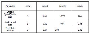
Alloy steel EN6 is chosen as the work piece material in the study presented in [1] Table 3.1 L27 orthogonal array and results

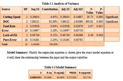
P-Value:InANOVAanalysis,thep-valueassumesacrucialrolebyindicatingthesignificanceofindividual variablesonthe output.FollowingtheAmericanstandardofmechanicalengineering,ap-valuebelow0.05isrequiredtomeetthecriterion ofstatisticalsignificance.Whenafactor'sp-valueisbelow0.05,itsignifiesanoteworthyimpactontheoutput.Inessence, thisfactorbecomestheprimaryinfluencer,accountingforvariationsordistinctionsinproductqualityorresponsevalues. Maintainingap-valuebelow0.05ispivotalforachievingenhancedproductqualityorimprovedresponses.
FValue:TheFvaluestandsasapivotaltermindataanalysis,particularlywhenmultiplevariablesexhibitp-valuesbelow 0.05, indicating a confidence interval of 95%. This prompts the question of identifying the most influential factor among thosewithp-valuesbelow0.05thatimpacttheresponse.Therelationshipbetweenthep-valueandtheFvaluecomesinto playhere:asthep-valuedecreases,theFvaluecorrespondinglyincreases.Among allvariableswithp-valuesbelow0.05, thefactorpossessingthelowestp-valueandthehighestFvalueemergesasthekeydriverinfluencingtheresponse.
R-Squared (R-sq): As per research methodology, an R-sq value exceeding 40% signifies a strong prediction agreement between input and output values. The presented table shows an R-sq value of 97.64%, indicative of a robust connection betweeninputandoutputvariables.Thus,a robustand meaningful relationshipisevidentbetweentheinputandoutput variables.

4.1 Response Surface Methodology (RSM):
Is a suite of statistical andmathematical tools that prove invaluable in modeling and enhancing the interplay between a response variable and a set of input factors? It holds particular significance within the industry due to its unparalleled efficacyinaligningwithweldingrequisites.Thisstudydelvesintotherealmofcost-effectiveproductpreparationandthe

enhancementofweldingintegritytoensureseamlessfunctionality.Thistechniqueiswidelyemployedtocurtailexpenses while concurrently bolstering product excellence, encapsulating these gains as functions of desired performance. By meticulously orchestrating experiments, this approach meticulously mitigates variance in processes, fostering a streamlinedavenuefordatacomprehensionandtheanticipationofoptimaloutcomes.
The subsequent objectives and gauges of RSM in the parameter design phase encapsulate its essence: proficiently sculptingandforecastingtheintricatefabricofrelationshipsbetweenfactorsandresponses.Thismethodologycomesinto its own when grappling with intricate interactions and curvature that characterize the nexus between factors and responses.
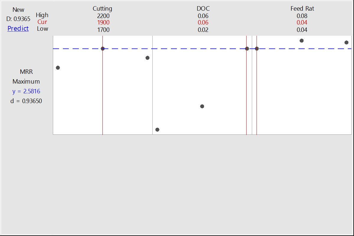
NumericalOptimization:Thefocalpointofthisstudyistodiscerntheparamountparametricconfigurationsthatyieldan utmostMaterialRemovalRate(MRR)withinthegrindingprocesswhileconcurrentlyensuringoptimalgrindingefficiency. To accomplish this, desirability analysis is harnessed, guiding the identification of parameter settings that foster the highestMRRachievementinthegrindingprocess.Theoptimizationendeavorswithintherealmofgrindingarecarriedout throughtheutilizationoftheMinitab18software,meticulouslyadheringtotheproceduralguidelinesandstepselucidated incomprehensivedetailherein.


The outcomes of the multi-objective optimization for Material Removal Rate are elegantly illustrated in Figure 4.1. An optimumMaterialRemovalRateof2.816(Gm./Min)iseffectivelyrealizedthroughthestrategicadjustmentofparameters, namely: (a) Cutting Speed (VC) set at 1900 rpm for A2, (b) Depth of cut at 0.06 mm for B3, and (c) Feed Rate at 0.04 (mm/rev)forC1.Theamalgamateddesirabilityfactor(D)attainsaremarkablevalueof0.93650,therebyunderliningthe substantialsuccessachievedthroughthisoptimizationendeavor.
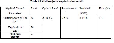
4.2 Validation Testing: To establish the reliability of the attained optimization methodologies, validation studies were meticulouslyexecuted.TheoutcomesoftheseconfirmatorytestsaresuccinctlypresentedinTable4.1,showcasingresults obtainedunder optimal circumstances.Acursoryexamination ofthetablerevealsthatthepercentagedisparity between projected and empirical outcomes is exceedingly minute, well within the 1% threshold. This underscores the substantial efficacy of single optimization in significantly enhancing the experimental alloy steel EN9 parameters within cylindrical grinding.
To affirm the robustness of the developed models outlined in Equations (3) and (4), three additional trials were performed, incorporating the Material Removal Rate's optimal values. Notably, the average measurements align to an Optimal Material Removal Rate of 2.816 (Gm./Min), which ensues from meticulous parameter adjustments: (a) Cutting Speed(VC)at1900rpmforA2,(b)Depthofcutat0.06mmforB3,and(c)FeedRateat0.04(mm/rev)forC1.
Anincisiveevaluationofmodelprecisionwascarriedout,gaugingthepercentageerror.Remarkably,theerrorfallsbelow the 10% threshold, substantiating the unequivocal alignment between predicted and experimental values [38]. Lastly, operating within the confines of experimental limitations, a conscientious endeavor was undertaken to pinpoint the optimalcylindricalmachiningposition,thusensuringtheattainmentofthemostdesirableoutcomes.
6. CONCLUSION
SummaryandProspectsfortheFuture:
A comprehensive series of experiments were meticulously conducted, exploring a diverse array of tool rotational speeds and welding velocities across three distinct levels using Taguchi's orthogonal array. The joint strength was meticulously evaluatedthroughrigoroushardnesstesting.
Keyobservationsgleanedfromthisstudyareasfollows:

1. Taguchi's orthogonal array proved to be an effective tool for pinpointing optimal process parameter configurations.
2. In the context of the larger-the-better quality characteristic, namely Material Removal Rate (MRR), a thorough examinationofthemaineffectplot(Figure3.1)revealedthatthesecondlevelof cuttingspeed(A2),thefirstlevel ofdepthofcut(B1),andthethirdleveloffeedrate(C3)collectivelyyieldthehighestMRRvalue.
3. Single optimization analysis through analysis of variance (ANOVA) (as shown in Table 3.3) validates the significance of depth of cut, contributing 92.06%, followed by cutting speed (4.65%), and feed rate (0.94%) in determiningMRRvalues,affirmingtheearlierconclusions.

4. Adheringtoresearchmethodology,anR-squared(R-sq)valueexceeding40%signifiesrobustalignmentbetween inputandoutputvalues.TherecordedR-sqvalueof97.64%underscoresarobustinterconnectionbetweeninput andoutputvariables.
5. Tofurthersolidifytheestablishedrelationshipbetweeninputsandoutputs,theadjustedR-sq(R-sq(adj))should similarly surpass 40%. In this instance, the R-sq (adj) value stands at 96.94%, further cementing the substantial relationshipbetweeninputsandoutputs.
6. ThepinnacleachievementmaterializedasanoptimalMaterialRemovalRateof2.816Gm./Min.Thiswas attained by harmonizing the following parameters: (a) Cutting Speed (VC) set at 1900 rpm (A2), (b) Depth of cut at 0.06 mm(B3),and(c)FeedRateat0.04mm/rev(C1).Thecompositedesirabilityfactor,D,culminatedat0.93650.The zenith configuration of input control parameters materialized as A2B3C1, culminating in a calculated grey relationalgradeof0.4413,asoutlinedthroughtheequation.
As this research paves the way for enhanced material removal in welding applications, future investigations could delve intobroaderparameters,expandedlevels,anddiversematerials,furtherenrichingtherealmofoptimizedmanufacturing processes.
References:
1. Pravin Jadhav, Pranali Patil, Sharadchandra Patil.: Optimization of Cylindrical Grinding for Material Removal Rate of Alloy Steel EN9 by Using Taguchi Method. Advances in Industrial and Production Engineering, Select Proceedings of FLAME 2020 (pp.851-859) https: //doi.org/10.1007/978-981-33-4320
7_76https://link.springer.com/chapter/10.1007%2F978-981-33-4320-7_76
[2] JitenderKundu and Hari Singh, Production & Manufacturing Research: An Open Access Journal, 2016 VOL. 4, NO. 1, 228–241http://dx.doi.org/10.1080/21693277.2016.1266449

[3] Swati S Sangale , Dr. A. D. Dongare ,optimization of the parameter in cylindrical grinding of mild steel rod (en19) by taguchimethodIJCIRAS|ISSN(O)-2581-5334September2019|Vol.2Issue.4
[4]S.Shaji,V.Radhakrishnan,Analysisofprocessparametersinsurfacegrindingwithgraphiteaslubricantbasedonthe Taguchimethod,J.Mater.Process.Technol.141(2003)51–59,https://doi.org/10.1016/S0924-0136(02)01112-3
[5]M.S.Dennison,N.M.Sivaram,D.Barik,S.Ponnusamy,TurningoperationofAISI4340steelinflooded,near-dryanddry conditions:acomparativestudyontool-workinterfacetemperature,Mech.Mech.Eng.23(1)(2019)172–182.
[6] M. Manikandan, S. Prabagaran, N.M. Sivaram, M.S. Dennison, A study on optimization of machining parameters in cylindricaltraverseroughandfinishcutgrindingprocesses,i-Manager’sJ.Mech.Eng.10(1)(2019)51.
[7]S.Rajarajan,C.RameshKannan,M.S.Dennison,AcomparativestudyonthemachiningcharacteristicsonturningAISI 52100alloysteelindryandmicrolubricationcondition,Aust.J.Mech.Eng.(2020)1–12.
[8] N. Alagumurthi, K. Palaniradja, V. Soundararajan, Materials and manufacturing processes optimization of grinding process through design of experiment (DOE) a comparative study optimization of grinding process through design of experiment (DOE) a comparative study, Mater. Manuf. Processes 21 (2006) 19–21, https://doi.org/10.1081/AMP200060605
