DYNAMIC STABILITY OF TRANSMISSION TOWER RESTING ON PILE FOUNDATION
1 Student, Civil Engineering Department, walchand college of engineering, Sangli , Maharashtra India
2 Professor, Civil Engineering Department, walchand college of engineering, Sangli, Maharashtra India
Abstract –
The dynamic analysis of a floating offshore wind turbine is at the frontier of green energy/renewable energy, and this structure has a big potential to provide clean, inexpensive energy quickly. Offshorewindturbinescontinue to rise in popularity. The growing use of renewable energy and technology in recent decades has widened the scope of energy study.
The major analyses in this study include the dynamic analysis of a tension legged platform built for wave loading. This paper also includes the methods for designing a 10 megawatt (10MW) triple spar with mooring. While the anchoring mechanism holds the platform in place and prevents drifting. It is also based on experimental fatigue damage and the calculation of fatigue damage and structure service life with a comparison of characteristics of various types of floating offshore wind turbine platforms. Based on strip theory, the bently mosesintegratedsoftware isemployed. A specific line of study seeks to go beyond the technical in order to evaluate the practical, practicable, and actual possibilities for dynamic analysis of offshore floating wind turbines.
1. INTRODUCTION
The advancement of infa in wind power technology has resulted in massive wind turbines. So far, it has only been put on land and in shallow or low water levels. The floating offshore wind turbine outperforms the onshore turbine. The floating wind turbine at sea will not disrupt life on land. Furthermore, there is a better wind efficiency inthesea,which aids in the creation of renewable energy in an inexpensive manner. The tension legged platform is a floating platform that is combined with buoyancy forces as well as tensile pressures generated by tube links, to the Hull and anchor into the seabed.
Unlike the only spar type that requires offshore assembly. Also, to reduce the cost of floating offshore wind turbines. High fidelity design and modeling tools are required for wind energy to establish itself as a dependable technology. Despite being miles distant from the coast, floating offshore wind turbines are more efficient and provide better speed and consistency in any direction. They also have a lower environmental effect. The floating offshore wind turbines
continue to be located further away from the localpopulation. It also has greater construction area in the seasandoceans.As a result, we can generate more cleanly sustainable energy.
2. FORMULATION AND METHODOLOGY
Equation of motion is used for dynamic analysis of floatingoffshorewindturbine.Thisequationofmotionbased onfiniteelementmethod.
Methodologyofanalysisanddesignforfloatingoffshore windturbineBentlymodelersoftwareisusedthissoftwareis onadvancedsuiteofhydrostaticsoftwarethatprovideforthe accurate calculation and simulation of offshore floating system.

2.1 Model Analysis
Generalpropertiesofmodel
1) Structuretype–transmissiontower building
2) Planarea–196sqmeter
3) Heightofbuilding–35.00m
4) Sectionproperty–ISA200X200X25
5) Steel–Fe500
6) Deadload– 1.00 KN/m
7) Liveload–5.00Kn/mforwingnode
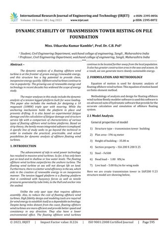
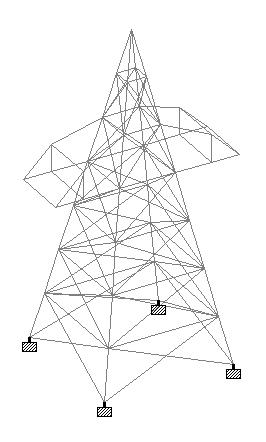
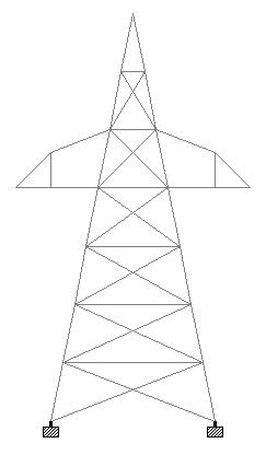
Here we are create transmission tower in SAP200 V.23 structuremodelareshowingbelow,
3. RESULTS
This chapter illustrate design, discus and conclude the findingsobtainedfromresearch.Herewearelatticetower are prepared and analyses then design pile foundation. Various results are obtained to analyze the changes in structuralbehaviorbuildingsuchasbaseshear,displacement etc.afteranalysiswegetbasereactionorloadandwedesign thepilefoundationhere.
A. Design of pile foundation of transmission tower
Designdata:
MaterialDataGradeofconcrete=35MPa
Densityofconcrete=25kN/m3
Modulusofelasticityofconcrete=29580.40MPa
Gradeofsteel=500MPa
Elasticmodulusofsteel=210000MPa
PileandPileCapDataDiameterofpile=1m
Widthofpedestal=1m
Numberofpileperleg=4
C/cdistancebetweenpiles=3m
Embedmentlenghtinsoil=6m
PilecaptopbelowHFL=2.2m
Depthofpilecap=1.5m
Overhangofpilecap=0.75m
SizeofpilecapWidth=4.5m
Length=4.5m
3. CONCLUSIONS
The main objective of this study is to learn about transmission tower and design pile foundation for transmission tower and demonstrate the effect of wind pressureontransmissiontower.Tocompletethisobjective, analysisanddesignoftransmissiontoweronpilefoundation incoastal regionweremodelled,designedandanalysedin STAADProV8.
Fromtheresults
1. vertical members are more prominent in carrying the load of the tower than the horizontal and transverse memberssupportingthecablesathigherheightsislikelyto haveamajorimpactonthebehaviorofthetowertheeffect ofthebendingmomentofthestructureisnotsignificant.
2. The geometry parameters of towers are efficiently considered as design variables and significant weight
reductions can often be achieved as a result of geometry changes.
3.TowerswithanglesectionsandX-bracingfurtherreduce weightafteroptimization.
4.Weareprovidingherepilefoundationbecauseofcoastal region. In coastal region wind pressure is very high and seismic condition also we are considering and we are analysedmodelandtheyaresafeinallcondition.
6.Inchapter5wearedesignedpile,so4no.ofpileproved eachfoundationanddiameteris1mandheightofthepileis 10.85m. and reinforcement for cap 14 bars 25mm and stirrups8mmat150c/cdistance.
7.Pilecapisdesignedby4.5x4.5andthicknessis1.5mand reinforcementforcap16mmat200c/cdistance.
FUTURE SCOPE
More work can be done in future to improve the understanding of transmission tower and they are listed below.
1.Tryingtochangetheshapeofthecrossarmcanleadto amazingresults.
2.Rapidurbanizationandincreasingdemandforelectricity, availability of land necessitates the use of tubular pole structures.
REFERENCES
1.Wang,Y.-Z.:Extremeclimatetestfortransmissiontower. TaipowerJ.657,018–019(2017)
2. Meyerhof, G.G.: Bearing capacity and settlement of Pile foundation. J Geotech. Eng. Div. ASCE 102(GT3), 195–227 (1976)
3.Holmes,J.D.(2007).Windloadingofstructures(2nded.). SponPress
4.Mara,T.G.,&Hong,H.P.(2013).Effectofwinddirectionon theresponseandcapacitysurfaceofatransmissiontower. EngineeringStructures,57,493–501.
5. Banik, S., Hong, H., & Kopp, G. A. (2008). Assessment of structuralcapacityofanoverheadpowertransmissionline towerunderwindloading.InProceedingsofBBAAVI(pp. 20–24).
6. Milano: International Colloquium on Bluff Bodies Aerodynamics&Applications,July2008.
7. Kyung, D., Choi, Y., Jeong, S., & Lee, J. (2015).Improved performanceofelectricaltransmissiontowerstructureusing connectedfoundationinsoftground.Energies,8,4963–4982
8. Kyung, D., Kim, D., Kim, G., Kim, I., & Lee, J. (2015). Improved performance of connected foundations for resilient energy transmission infrastructure in soft soils. Sustainability,8,1–15.
9.Darestani,Y.M.,Shafieezadeh,A.&Cha,K.(2019).Effectof modelling complexities on extreme wind hazard performanceofsteellatticetransmissiontowers.Structure andInfrastructureEngineering,1573–2479.
10. Shu, Q., Huan, Z., Yuan, G., Ma, W., Yea, S., & Zhou, J. (2018).Impactofwindloadsontheresistancecapacityof the transmission tower subjected to ground surface deformations.Thin-WalledStructures,13,619–630.
11. BSI (1986), "British standard code of practice for foundations", BS8004, British Strandard Institution (BSI), London.
12.Chin,F.V.(1970),"EstimationoftheUltimateloadofpiles no t carried to failure", Proc. of 2nd southest Asian ConferenceonSoilEngineering,pp.81-90.
13. IEEE (2001), "IEEE Guide for Transmission Structure Foundation Design and Testing. (Overturning Moment tests)",IEEEStrandard691-2001.
14. ISSMFE (1985), "Axial pile loading test-part 1: static loading", Geotechnical Testing Journal, ASTM, Vol.9, No.2, pp79-89.
15. JEC (1979), "Design Standard for Power Transmission Supports",JEC-127-1979,StandardoftheJapaneseElectro technicalCommittee.
16.JGS(2002),"StandardforVerticalloadingtestofpile", JGS-1813-2002,JapaneseGeotechnialSociety.
17. Chin, F. V. (1970), "Estimation of the Ultimate load of piles not carried to failure", Proc. of 2nd southest Asian ConferenceonSoilEngineering,pp.81-90.
18. Dajin Liu (2003), "Structural Analysis of Combined FootingonPiles",Practiceperiodicalonstructuredesignand construction,ASCE,Vol.8,No.1,pp.22-24.
19. Wang Jiying. Probe of Pile Foundation Design in Karst Area[J].NorthernCommunications,2007(12):47-48
20.TANGHuiming.Foundationsofengineeringgeology[M]. Beijing:ChemicalIndustryPress,(2008).
21.CHENGYe.StabilityEvaluationMethodandApplication ofHighwayRoadbedandBridgeFoundationinKarstRegion [D].Hunan,HunanUniversity,(2005).
22. Wang Jiying. Probe of Pile Foundation Design in Karst Area[J].NorthernCommunications,
BIOGRAPHIES (Optional not mandatory )
Miss UtkarshaKumarKamble Student, Civil Engineering Department, walchand college of engineering, Sangli , Maharashtra India
Prof.Dr C.B Pol Professor, Civil Engineering Department, walchand college of engineering, Sangli, Maharashtra India