Depict and Analysis of the nomadic kuroshio turbine blades
Yadluri Ravi Kishore 11Sr.Assistant Professor, Dept of Mechanical Engineering, Aditya College of Engineering and Technology , Affiliated to JNTUK , Surampalem Andhra Pradesh, India. ***
Abstract - The most commondevices usedforextractingthe ocean current energy are thecurrentturbines.Mostpeopleuse the wind turbine blade design methods for the horizontal axis current turbine design; however, the current turbines operate in the water, and their physical behaviours are more like marine propellers. In this paper, two turbine blade design procedures are adopted. The first design procedure is similar to the propeller designs, and the second design procedure is to use Genetic Algorithm and boundary element method (BEM) to find a geometry which can provide the maximum torque. After completing the designs, hydrodynamic performances of the marine current turbine are then computed and analysed by the potential flow BEM and the viscous flow RANS method. The computational results show the geometries designed by the presented procedures can not only satisfy the hydrodynamic design goal, but also predict the delivered power very close to the experimental data. After the blade performance meets the design target, the performances of designed 20kw nomadic type Kuroshio turbine including the floating body at different operation conditions are demonstrated in the paper. Also, the structural strengthofthe turbine blade is computed by FEM, and the results are evaluated to see if the design complies the rule requirements.
Key Words: Kuroshio, current turbine blade design, boundaryelementmethod,RANS,FEM


1.INTRODUCTION
Withtheinternationalhighlyattentiontoallkindsofenergy issues, Taiwan is bound to examine the state of energy problem in the country. Since Taiwan currently does not haveexploitationofnon-renewableenergysources,itmust rely on foreign imports and lack of the ability to supply energy on its own. In this situation, the application of renewableenergyisanothersolutiontotheenergyproblem. There are many types of renewable energy, such as solar power and wind power that have been used successfully. However, from the point of view of the country's use of electricity, ocean current power generated from ocean energyisnotaffectedbyseasonalandweatherfactors.Itcan providestableenergy,anditisaverygoodchoiceasabaseloadenergyresource.TheKuroshiothatflowsthroughthe outerseasofTaiwanistheoceancurrentthatbeginsfrom Philippines and crosses through Taiwan and flows along Japaninthenortheastdirection.Twomostcommondevices used for extracting the ocean current energy are the horizontalaxiscurrentturbineandtheverticalaxiscurrent
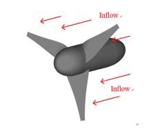
turbine,andthepowergenerationsystempresentedinthis paperisaNomadicKuroshioturbine(NKT,asshowninFig. 1)whichisahorizontalaxiscurrentturbinedevelopedusing theKuroshioCurrentasitsenergysource.
In this paper, the design procedure and performance analysis of the NKT are presented. First of all, the design targetofthisgeneratormustbeestablished.Thegenerator designed in this paper is based on two horizontal shaft generators and must reach 20kW of power generation. In other words, a single-sided turbine must achieve a design targetofatleast10kW.Mostpeopleusethewindturbine bladedesignmethodsforthehorizontalaxiscurrentturbine design;however,thecurrentturbinesoperateinthewater, and their physical behaviours are more like marine propellers. In this paper, two turbine blade design procedures are adopted. The first design procedure is similartothepropellerdesigns,andliftinglinemethod[1-2], lifting surface design method [3], and boundary element method[4]areused.Theseconddesignprocedureistouse GeneticAlgorithmandboundaryelementmethod(BEM)[5] tofindageometrywhichcanprovidethemaximumtorque, and also used to design chord-length distribution. After completingthebladegeometrydesigns,boththeBEMand theviscousflowRANSmethod[6]areappliedtotheanalysis ofperformancesofcurrentturbinestoconfirmthedesigns. Theperformanceswerecalculatedbasedona1/5scaleof 20kWdemonstrationunit;however,theexperimentalunit was tested with a 1/25 scale at NTU (National Taiwan University)towingtank.Inthispaper,wealsopresentthe comparison between computational results and experimental data, and the comparison shows that the
geometriesdesignedbythepresentedprocedurescannot onlysatisfythehydrodynamicdesigngoal,butalsopredict the delivered power very close to the experimental data After confirming that the blade performance meets the design target, we further investigate NKT more comprehensively. It is no longer only to discuss the performanceoftheturbinebladesonly,buttheeffectsonthe turbineperformanceafteraddingthefloatingbody.Alsothe overallNKTperformancesweresimulatedunderdifferent conditionsduringoperations,suchasbreakdownofoneside turbine.Aftercompletingthebladehydrodynamicanalysis,a seriesofstructuralstrengthverificationsareperformedby finiteelement method(FEM)tocheck whetherthedesign meetsregulatoryrequirementsafteraddingthesafetyfactor.
2.HYDRODYNAMIC DESIGNS AND VALIDATIONS
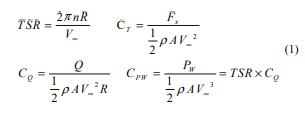
Beforepresentingthedesignprocedure,wefirstintroduce several important coefficients related to the turbine performance. These coefficients are the tip speed ratio (TSR),thrustcoefficient(CT ),torquecoefficient(CQ)and powercoefficient(CPW).Theyaredefinedasfollows.


The presented NKT design is completed via two major designprocesses.Sincetheoceancurrentturbineoperates in water, its physical characteristics are more similar to thoseofmarinepropellers.Therefore,thedesignofNKTis firstcarriedoutbyaprocesssimilartothepropellerdesign. TheliftinglinemethodandLagrangemultipliermethodis first used to obtain optimum circulation distribution, and then lifting surface theory help us to get blade geometry, namely,thepitchandcamberdistribution.Thesecondstep isbasedonthegeneticalgorithmmethod.The goalofthis procedure for the NKT is to achieve the maximum CQ (maximumtorqueandpower).Aprocedurethatisconceived anddevelopedbythegeneticalgorithmmethodtoadjustthe pitch and camber distributions to reach our goal. The optimization of geometry parameters in the genetic algorithm computation process is performed by the boundary element method (BEM) because its efficient computationaltime.ThepotentialflowBEMusedhereisa self-developed, perturbation potential based boundary elementmethod,andawakealignmentnumericalschemeis establishedforthecurrentturbine.Table1showstheNKT geometry parameters. Detail design procedure was presentedinthelastAWTECconference[7].

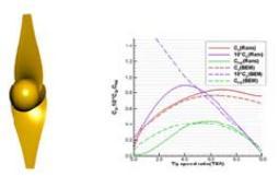
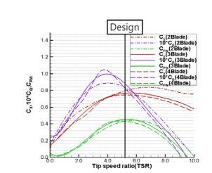
After the blade geometry was designed, we also designed different numbers of blades and hydrodynamic performancesarealsocomputedandanalysedbyBEMand RANSmethodfor2,3,and4bladesrespectively.TheRANS computations are carried out by the commercial CFD softwareSTARCCM+.Fig.2showsbladegeometryofthe2bladedesign alongwithand theresultsofRANSand BEM analysis.Fig.3andFig.4showthoseof3-bladeand4-blade. Fig. 5 compares the results of the analysis of the three different blade numbers, and the position marked by the blacklineisthedesignpoint.Itcanbeseenthat3-bladeis thebestatthedesignpointandisalsothemoststableone.
II.OverallNKTPerformanceAnalysis

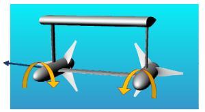
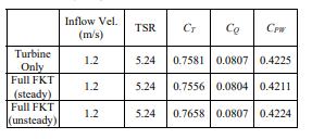
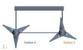
Theobjectsdiscussedintheprevioussectionsarethedesign andperformanceofNKTbladegeometry.Inthissection,the overall performance of the NKT is discussed. Because the NKTiscomposedofafloatingbodyandtwoturbines,and therotationaldirectionofeachturbineisoppositetoeach other(showninFig.6).Inorderto understandtheoverall NKTunitperformance,wehavecomputedforcesofNKTata slowerinflowspeed,1.2m/s,underthefollowingconditions:
Singleturbine,
Withthenomadicbody,andusingsteadyRANS
With the floating body, and using unsteady RANS (URANS).Themeanvaluesaretakenforthecomparison.
I.ComputationalResultsofSingleTurbine
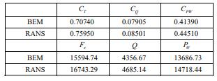
After the final design of the blade was completed, the performance was computed with a 1/5 scale 20kW demonstration unit (as shown in Fig. 1). The diameter of bladeis5m,therotationspeedis0.5rps,andtheinflowisset as 1.5m/s, and number of the blades is 3 (Table 1). The performanceiscalculatedbypotentialflowBEMandviscous flow RANS method, and the results are shown in Table 2. FromTable2,onecanseethateithertheBEMmethodorthe RANS method, the output powers show that this design meetsthedesigntargetof10kWforeachturbine.
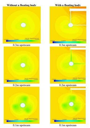
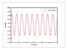
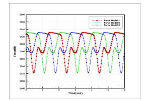
ThereasontousebothRANSandURANSforcomputationsis to double check our computational results. The computed performancesoneachturbineisshowninTable3,anditis obvious that whether there is a floating body or not, the differencesarenotlarge.Wetheninvestigatetheinfluence ofthefloatingbody.Fig.7showstheflowfieldatdifferent locations upstream of turbine blades with and without a floating body,andthe distancesupstreamare0.3m,0.2m, and0.1mrespectively.FromFig.7,onecanseethattheflow fieldat0.3mupstreamisobviouslyaffectedbythefloating body; however, the influence of floating body gradually decreased.Theflowfield0.1mupstreamshowsthefloating bodyhasalmostnoeffect.Wethenlookintotheforceson eachbladeasitrotates(Fig.8),andtheforcevariationson eachbladeisobviouslyaffectedbythefloatingbodyandthe
struts. The magnitude of force variation on each blade is about2%.Fig.9thenshowsthetotalforceononeturbine, whichisthesumofforcesonthreebladesastheyrotate,and theforcefluctuationisonly0.6%.Therefore,wecanconfirm againthattheinfluenceofthefloatingbodyisnotsignificant onbothforcesandflowfield.
III.NumericalResultsvs.ExperimentalData

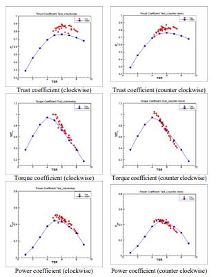
Theexperimentofa1/25scalemodelwascarriedoutatthe NTUtowingtank,andthemeasureddataarecomparedwith the RANS computational results as shown in Fig. 10. The experimental data obtained by two turbines rotating clockwiseandcounterclockwise.FromFig.10,themeasured datafromtwoturbinesarequiteclosetoeachotherforboth torque coefficients CQ and the power coefficients CPW, and there are some differences between two turbines for the thrust coefficients CT. For the comparison between numerical results and measured data, we can see that the
numerical results slightly under-predict the thrust coefficient;however,thenumericalresultsareverycloseto theexperimentaldataforbothtorquecoefficientCQandthe powercoefficientCPW

3.SIMULATION OF ONE SIDE MALFUNCTION
OneofthepossiblesituationthatmightoccurwhentheNKT operatesisoneturbinemalfunction.Wetrytounderstand thatsituationbynumericalsimulationinthissection.
To simulate one turbine breaks down, the setting of inlet conditionsandturbineoperatingconditionsareshowedin Table4,andFig.19illustratestherelativepositionbetween Turbine1andTurbine2.Theperspectiveisdownstreamof theNKTturbine.Inthissimulation,Turbine1(therightone) keepsarotationalspeedof0.5rps,andTurbine2(theleft one) is stationary. The inlet velocity is 1.5 m/s for both turbines. Table 5 are the results obtained from the RANS computations,anditshowstheaxialforcesandmomentson NKTinthreedirections,andSincetheanalysisassumesthat the center of mass is at (0,0,0) position, namely, the two turbineslieonthesameline,theforcecausedbythefloating body leads to y direction torque (pitch). In the actual situation, the center of mass should be in more forward position,sothatthearmisreducedandthetorqueisalso reduced.Becauseonlyonesideturbineoperates,theforces onNKTarenotstable,whichbringsonthetorqueinother direction. Table 6 shows the axial forces and torques on Turbine1andTurbine2respectively.Fig.12showstheflow filedofonesidemalfunctionsituation.Becauseonturbine breaksdown,theforcesandtorquesontwoturbinescannot be cancelled, and the uneven forces and the torques from different directions cause instability of the NKT. Based on theanalysisabove,theNKTmightrotateirregularlyoreven overturnintheoceanwhenthissituationtakesplace.
4.STRUCTURE ANALYSIS RESULT


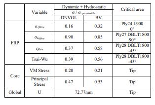
Inadditiontotheaboveanalysisofhydrodynamic performance, NKT structure analysis is discussed in this section. The NKT turbine will be placed in the ocean and mustoperateintheKuroshioforalongtime,itsstructure notonlyneedstoresistdynamicpressureandhydrostatic pressurebyfluidbutalsomeetstherulerequirementsafter consideredthesafetyfactor.FRPisusedasmaterialofthe blade, and the structure strength is analysed by the finite element method (FEM). We applied Tsai-Wu Index and maximumstresscriteriontoevaluatewhetherthefibreof eachlayerofFRPreachesdestructionornot.Thestrengthof core material was examined by Von Mises stress and Principalstress.Theparametersobtainedbyaboveanalysis methods are then checked against the BV and DNVGL regulations.

The blade structure was analyzed by static loading simulation,andFig.13illustratestherelationshipbetween inflowandNKTinFEManalysis.TheFRPstructureisshown inFig.14,andbladeisdividedintosuctionsideandpressure side.FRPisasandwichstructure(asshowninFig.14),the insidepartisthecorematerialandtheoutsidepartisFRP. Weappliedhydrodynamicpressureandhydrostaticloadof 50mdesigndepthtothebladesurfaceforFEManalysisand overalldeformation,theTsai-Wuvaluesoffiberineachlayer ofFRP,thestressvaluesparalleltothefiberdirectionσ// fiber , the stress values vertical to the fiber direction σ ⊥ fiber , sheer stress fiber τ , and the Von Mises stress, and Principalstressofthecorearecomputed.
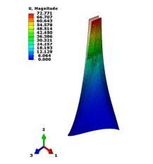
Fig. 16 The deformation at the tip of the blade is 72.77mm, which is about 3.83% relative to the blade length.

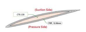
Table 7 shows the results of structure analysis, and all parametersaredisplayedinthewaythatthestressdivided by permissible stress. If the number is smaller then 1, it means that structure strength meets the regulation. AlthoughthevaluesofTsai-Wu,σ⊥fiberandfiberτareall smaller than regulation requirements, the σ ⊥ fiber of the 27th layer fibre (DBLT1800 90°) is quite close to the allowablestress.Fig.15showsthatstressdistributionofthe 27thlayerfibre(DBLT180090°),itcanbeobservedthatthe area close to the allowable stress value is not small. The reasonisthatDBLT1800isaunidirectionalmaterial,andits strengthintheseconddirectionisweak.Itmaybebeyond the specification if the forces are slightly changed. To improvethisproblem,wecanincreasethestrengthofthe blade in the direction of fibre length which is 0 unidirectional material. Table 7 also shows the strength analysis of the core material. The Von Mises stress and Principalstressarealllessthantheallowablestress,andit indicatesthatthestrengthofthecorematerialissufficient. Fig.16showsthedeformationatthetipoftheblade,anditis 72.77mm,about3.83%relativetothebladelength.
5. CONCLUSIONS
In this paper, the design procedures of a NKT are briefly introduced,andtheperformancesofdesignedgeometryare computed by both potential flow BEM and viscous flow RANSmethod.Thecomputationalresultsarealsocompared totheexperimentaldata.Alltheresultsconfirmedthatthe designedNKTgeometryachievedthedesigngoal.Inaddition to the analysis of the blade geometry, the overall NKT performanceswerealsoanalysed,andresultsshowthatno significant influence on performances with the nomadic body.Wealsosimulatethesituationthattheturbineshave onesidemalfunction.Thetwoturbinesareunbalancedand thenleadtotheoverallNKTmightbeinirregularrotations inthecurrent.Intermsofstructurestrength,weinvestigate whether FRP materials can withstand long-term stress in

oceancurrentbyFEM.OverallstrengthofNKTstructureare sufficient.However,becauseoftheunidirectionalmaterials, someFRPlayersmightbeincriticalconditionaccordingto the rule requirements. To prevent the structure damages, thematerialshouldbestrengthenedinotherdirections.
REFERENCES
[1] Y.-S. Luo, Investigation of the Current Turbine Performance by Computational Methods, M.S. Thesis, National Taiwan Ocean University, Keelung, Taiwan (2013).

[2] C.-Y. Hsin, Efficient Computational Methods for MulticomponentLifting LineCalculations,M.S. Thesis,MIT, Cambridge,MA,USA(1986).
[3] S.-Y. Wang, Improvement of Marine Current Turbine Blade Design by Using the Genetic Algorithm, M.S. Thesis, National Taiwan Ocean University, Keelung, Taiwan(2015).
[4] J.E. Kerwin, W.B. Coney and C.-Y. Hsin, “Optimum circulationdistributionsforsingleandmulti-component propulsors,” 21st ATTC Conference, Washington, DC, USA(1986).
[5] C.-Y.Hsin,S.-Y.Wang,J.-H.ChenandF.-C.Chiu,“Design ofFloatingKuroshioTurbineBladeGeometries”,Journal of Taiwan Society of Naval Architects and Marine Engineers,Vol.35,No.3,pp.145-153,2016
[6] C.-Y.Hsin,S.-Y.Wang,J.-H.ChenandF.-C.Chiu,“Design of Floating Kuroshio Turbine Blade Geometries”, 3rd Asian Wave and Tidal Energy Conference (AWTEC2016),Oct.24-28,2016,Singapore
[7] D.S. Greeley and J.E. Kerwin, “Numerical methods for propeller design and analysis in steady flow,” SNAME Trans.,Vol.90,pp.415-453(1982)
