DESIGN OF CONVEYOR SYSTEM FOR UNLOADING HEAVY GOODS
Sanket G. Saptasagare1 , Suyash A. Nikam2 , Omkar S.Erandole3Abstract - The aim of this project is to produce the mechanical design of a conveyor system for unloading heavy goods. The current unloading process of heavy goods like LPG gas cylinder is improper which may lead to some major problems. This design of conveyor system will overcome those mistakes done during unloading of LPG gas cylinders. The thorough study is to be done on various designs of conveyor system. From the data analyzed at simple and cost-efficient design of conveyor belt is done. Design of this conveyor system is performed using Solid works and Computer Aided Drafting (CAD).
Keywords: Conveyor, Cylinder, Unloading, LPG, System


1.INTRODUCTION
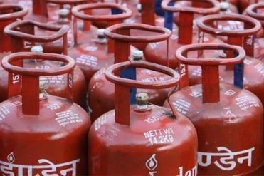
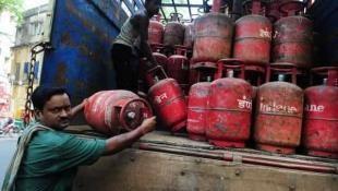
The major problem in any organization is material handling from one processing station to another. This major problem is solved by conveyor systems. Conveyor belts play a significant role in material handling in any manufacturing unit or dispatching unit. But in small sales industries or warehouses, it becomes financially impossible for that organizationtoinstallaconveyorsystem.Theremorehuman efforts are required and this leads to some major human errors.Theremorehumaneffortsarerequiredandthisleads to some major human errors. At small-scale organizations likeanLPGgascylinderwarehouse,theunloadingprocessof LPGgascylindersisdonebyaconventionalmethod.TheLPG gascylindersaredirectlythrownfromthetruck towardsthe land. This practice may lead to the leakage of LPG gas cylinders and many other damages. This is the complete financial loss of the organization because of the improper unloadingprocess.
Conveyor systems are durable and dependable in material transportation and warehousing. Given various standards of operation, there are diverse transport frameworks to be specific: gravity, belt, screw, chain, spiral, grain conveyor systems,etc.Thedecisionhoweverreliesuponthevolumeto be transported, the stature or separation of transportation, andthenatureofthematerial.
A belt consists of an endless and flexible loop of superior material, with two end pulleys (driver and driven) fixed in placeandsupportedbyrollers.Pulleysareutilizedforgiving the drive to the belt through the sprocket and wheel mechanism operated by the human hand
Volume: 10 Issue: 07 | July 2023 www.irjet.net

2.LITERATURE REVIEW
The research on conveyor system done by F.I.MALEK, M.MUAZ, S. RUBIAH,M.N.MANSOR,M.A.MUDAsaysthata conveyor system is a common piece of mechanical handling equipment that moves materials from one location to another.Manykindsofconveyingsystemsareavailable,and are used according to the various needs of different industries.Thecurrentdesignoftheconveyermachineused timing belt that connected at the motor to move the shaft. The problem of the current design is the timing belt disheveled and shaft was slipping. For the improvement we use sprocket and chain as drive mechanism. Beyond the above improvement the conveyor system is expected to work. This project also helps student to utilize their engineering information and improve the skill of student in solvingthemechanicalproblem


The research on conveyor system done by KONAKALLA NAGA SRI ANANTH, VAITLA RAKESH, POTHAMSETTYKASI VISWESWARAO
says that the belt conveyor is the transportation of material from one location to another. Belt conveyor has high load carrying capacity, large length of conveying path, simple design, easy maintenance and high reliability of operation. Belt Conveyor system is also used in material transport in foundry shop like supply and distribution of molding sand, molds and removal of waste. This paper provides to design theconveyorsystemusedforwhichincludesbeltspeed,belt width, motor selection, belt specification, shaft diameter, pulley, gear box selection, with the help of standard model calculation.
3.PROPOSED DRAWING OF MODEL
Conventional design of conveyor belt is too costly therefore small organizations cannot afford it. So, we proposed a new designwhichcostlowthancurrentdesign.
3.DESIGN OF COMPONENTS
The prime components used in the system are Idler pulleys(shaft), bearings, lever used for braking system. The followingaretheformulasforgettingthedimensionsforthe constrainedconditionsofdesign.
Forshafts.Totaltwoshaftsarepresentinthesystem,oneat
theupper endandanother atthelower end.Asthe beltwill move around the shaft the shaft is mainly subjected to twisting as well as bending moment as the load of heavy goods will be there on the shaft. The proposed design is basedinthat.
Here,
M–MaximumBendingMoment
T–MaximumTwistingMoment
σ–BendingStress
r–ShearStress
AccordingtomaximumShearStressTheory √
AccordingtomaximumPrincipalStressTheory
From the above equations whichever value of “d” means diameteroftheshaftisbiggeriswillbeconsidered.
For Lever. The dimensions of prime components of lever to be calculated for the safe design of lever are diameter and lengthofbossanddimensionoflevercrosssection.
Db –Diameterofboss
DL –Lengthofboss
D–Diameterofbreakshaft
Db =1.6*d
DL =1.5*d
International Research Journal of Engineering and Technology (IRJET) e-ISSN: 2395-0056

Volume: 10 Issue: 07 | July 2023 www.irjet.net p-ISSN: 2395-0072
Consideringtherectangularcrosssectionoflever
Let,b=widthoflever
h/t=thicknessordepthoflever
Thewidthofleverisgivenas
��=2������3��
Itis2or3timesofthethickness/depth
The lever is subjected to bending moment, the maximum bendingmomentontheleveristakenneartheboss.
i.e��=��×(����–0.5D��)
Here,Le=lengthoflever,whichisgivenby
Le=P×T(Force×Torque)onshaft. As,maximumbendingstress
σ=(6P*[Le –0.5Db])/bh2
4.CONSTRUCTION
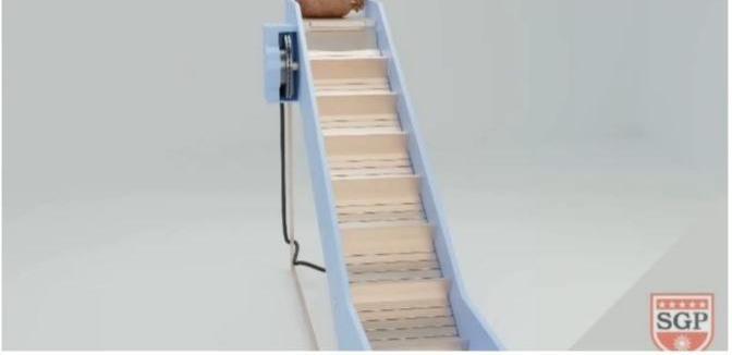
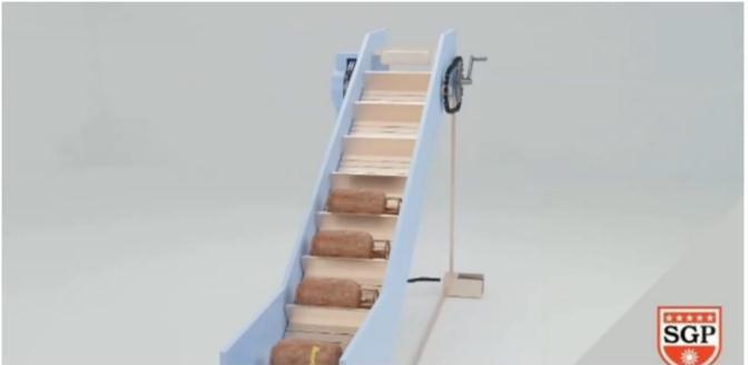
This conveyor system consists of components like main frame idler pulleys, conveyor belt braking system and chain and sprocket mechanism. The upper shaft is placed on the upper side of the frame with the help of bearings. Similarly, lowershaftisplacedonlowersideoftheframewiththehelp of bearings. The conveyor belt is between the upper shaft and lower shaft. The braking system is placed belt and the lever is there to operate it. The chain and sprocket mechanismsisconnectedtotheupperidlerpulley.
5.WORKING
This proposed design is for unloading heavy goods mostly LPGgascylinder.TheconventionalmethodofunloadingLPG gas cylinder leads to damage of LPG gas cylinder body and otherpart.TheLPGgascylinderareplacedattheupperend LPGgascylindergetstuckedonbeltduetotherampsonthe conveyor belt. A chain and sprocket mechanism is attached tomesystem.Onesthebeltmovesfromupperpulleyfurther it travels downward due to gravity. High quality bearing to be used at idler pulley for the smooth functioning of the whole system. But me main barriers is that if the speed of system suddenly increases due to heavy load then some accident may occur. So to avoid that braking system should bethere.Incurrentbrakingsystemproposedinourmodel.A roller is present model. A roller is present at the bottom of conveyor belt. The brake pad is present on it and a lever is therewhichisoperatedbyworkersfootleverispressedme brake pad comes in contact with bottom side of conveyor beltandduetofrictionbrakeisapplied.
6.CONCLUSION
TheunloadingprocessimplementedatthewarehouseofLPG gas cylinder causes damage to the LPG gas cylinder. This damageincludesdentsatthebody,leakages,leakageatvalve of LPG gas cylinder. The organization has to spend its valuable funds for repairing the damage of the LPG gas cylinders. So we decide to make a conveyor system to overcome this problem. We studied the various conveyor systemthoroughlyandcameupwiththisdesignofconveyor system. This conveyor system is simple in design, cost efficient than other conveyor system. This conveyor system canbeusedatmanyplacesforunloadingheavygoodseasily. Hence,thetime,money,andhumaneffortwillbereducedue tothisconveyorsystem.
7.REFERENCES
• F.I.Malek, M.Muaz, S.Rubiah, M.N.Mansor, M.A.Muda, Design and development to improve mechanism of conveyer system pat – 1, 2nd Integrated design project conference (IDPC) 2015, Faculty of mechanical engineering,UniversityofMalaysiaPahang
• Konakalla Naga Sri Ananth, Vaitla Rakesh, Pothamsetty Kasi Viswesarao, Design and selecting the proper conveyor belt, International journal of advance engineeringtechnologyE-ISSN0976-3945
• Hitesh J Soni, Ronak R Patel, Design and optimization of idlerforbeltconveyor,Internationaljournalforscientific research & development Vol.2, Issue 04, 2014, ISSN (online):2321-0613
• M.A, A., Latest Developments in Belt Conveyor Technology. MIN Expo 2004, Las Vegas, NV, USA. September27,(2004).
• Ahmed, N.N.a.E.-N., Survey of Research In Modeling Conveyor-Based Automated Material Handling Systems In wafer fabs. Proceedings of the Winter Simulation Conference(2007).2007.
• Lan, C.-H., The design of a multi-conveyor system for profit maximization. International Journal Advance Manufacturing Technology, 22: 510- 521(2003). 2003. R.S.khurmi & J.K.gupta “Design of machine elements.” Eurasiapublishinghouse(pvt.)Ltd,fifthedition.
• Design of shaft using Concept In design of machine elementbySusmitha(KLUniversity)
