STRUCTURAL BEHAVIOUR OF SQUARE AND ELLIPTICAL CROSS SECTIONS OF STEEL TUBULAR COLUMNS WITH DECONSTRUCTABLE SPLICE JOINT
Nehana V.G1 , Krishnachandran V.N2
1P.G Student, M. Tech in Structural Engineering, N.S.S College of Engineering, Kerala, India

2Assistant Professor, Department of Civil Engineering, N.S.S College of Engineering, Kerala, India
Abstract - A steel tubular column is a vertical structural member used in construction to provide essential support. Splice joint is a method of joining two members end to end. When the material being joined cannot be obtained in the desired length, the splice joint is used. For high rise buildings the continuity of columns may break, hence splice connections are provided and columns are installed. Splice joints are deconstructable type joints as the failed parts can be repaired, reassembled or can be even removed. Deconstructable steel structure system possesses good construction efficiency and quality. This paper focuses on developingmodelsofsquareand elliptical cross sections of steel tubular columns with deconstructable splice joint using a finite element modeling software ANSYSandstudytheirstructuralbehavior. Thispaper includes a parametric study on the effect of axial loading by varying splice length and thickness, bolt diameter and pattern of square and elliptical cross sections of steel tubular columns with deconstructable splice joints. Load v/s deflection curves are obtained which gives the maximum strength and ductility cases. Cyclic load testing is done on square and elliptical cross sections to obtain bending moment rotation curves.
Key Words: Local buckling, Splice joint, ANSYS, Deconstructablejoints,HighstrengthBolt
1.INTRODUCTION
In addition to the benefits of high construction efficiency, good construction quality, and sustainable development associated with prefabricated steel structures, deconstructable steel structure systems enables quick disassemblyandreuseofstructuralmembersfollowingthe completionofthestructure.Deconstructablesteelsystems thereforehavegreaterpromiseintheengineeringfield[4]. Splicingjointismadeoflowersquaresteeltubularcolumn, uppercolumn,fournumbersofspliceplatesandnumberof highstrengthbolts.Usageofhighstrengthboltgiveshigher strengththanregularbolts.Highstrengthboltsaremadeof somealloysteel.These boltsensuresthatstructureremains safe even under harsh weathers. The splice plates are designedasfournumbersofindependentplatesinorderto makesurethatthespliceplateswellfitintothefourother componentplatesofthecolumn.Steeltubularconstructions withdistinctadvantagesarebeingemployedmorefrequently aslongspanskyscrapersandhigh-risebuildingscontinueto
emerge[12].Deconstructablestructuraldesignalsorefersto the use of reusable materials in the design stage to create structural components that are simple to assemble and disassemble[11].Atpresenttheresearchondeconstructable steelstructuresystemisverylimited.Whileclosedsection column-to-columnsplicingjointsfrequentlyusefullywelded connections, which can't satisfy the requirements of convenient disassembly, the majority of the column-tocolumn joints use fully bolted connections [4].The current studyproposessquareandellipticalcrosssectionsofsteel tubular column with conventional high-strength bolts in ordertorealizedeconstructableconnectionofclosedsection steel column splicing joints. 3-D finite element model was builtusingAnsysWorkbench2022R2softwareandfurther validated against the experiments, which may serve as an important reference for its use in real-world engineering applications.Non-linearanalysisisbeingconducted.Incyclic loading tests, the bending moment rotation curves were obtained.Axialloadingsweregiventosquareandelliptical column sections and corresponding ultimate load and deflectioncurveswereplotted.
2. VALIDATION
Cyclic loading is being tested for validation. The material propertiesanddimensionforvalidationistakenfromwork by[4]asshowninTable2andTable2.Specimenchosefor validation were splice connection in square steel tubular column with splice plates being exactly placed at middle position. The square steel tubular column of size 2245mmx220mmx10mm is taken for validation. High strengthtypeofboltischosenwithnominaldiameterM24, 10.9gradeboltandthetotalnumberofboltsis64.Thesplice plate of size 785mmx168mmx14mm is used. For cyclic testingbottomisfixed.Atthetopdegreesoffreedominthe verticaldirectionandrotationdirectioninthebendingplane are released. Element type used is SOLID 186(steel plates).Adaptive meshing is used for modeling. Connector elements BEAM 188(Bolt) is used for modeling bolts[11]. Henceboltsaremodeledas1Dbeamelement.Elementsizeis 12mm.Element shape of meshing is HEXAHERDON with higher order element of 20 nodes. Total deformation, equivalent plastic strain and directional deformation is obtainedafteranalysisusingANSYSworkbench2022R2.
LoadingisappliedasperFEMAprotocolenlistedinTable3. Asperthisprotocol0.375%ofdriftisgivenfirst.Above24%ifastructurewithstandstheloadwithoutfail,thenthe structureissaidtobeseismicallybestsuited.Hencethereis noneedtotestabove4%.LoadingHeight=6.9/0.00375= 1840mm.


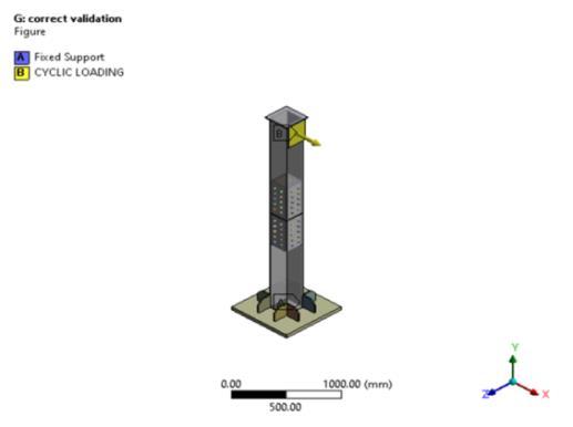


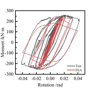
Table- 4:Validationresultsaftercyclicloadingtest
3. Effect of axial loading on square steel tubular column with deconstructable splice joint.
Thesquaresteeltubularcolumnwithdeconstructablesplice joint modeled for validation is chosen and tested for axial loading by considering four parameters namely splice thickness, splice length, bolt diameter and bolt pattern. Boundaryconditionadoptedisattopaxialloadappliedand bottom is hinged. Under each parametric study load v/s deflectioncurveisobtainedandstudiedtheirfailurepattern.
3.1 Effect of axial loading by varying splice thickness

Spliceplateofthickness14mm,12mm,10mm,8mmand6mm are variedandtested.
Chart-1: Loadv/sDeflectioncurvebyvaryingsplice thickness
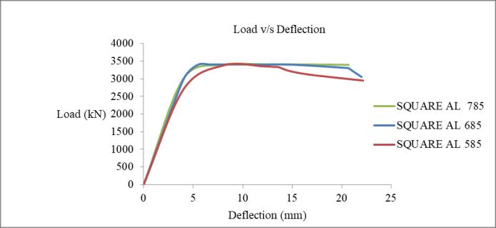

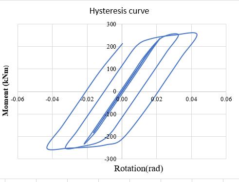
Table-5: Ultimateloadandultimatedeflection
3.2 Effect of axial loading by varying splice length
Spliceplateoflength785mm,685mmand585mmaretested underaxialloading.
Chart-2: Loadv/sDeflectioncurvebyvaryingsplice length
Table-6: Ultimateloadandultimatedeflection
3.3 Effect of axial loading by varying bolt diameter
Boltdiametersarevariedfrom24mm,22mm,20mm,18mm and16mm.
Table-8: Ultimateloadandultimatedeflection
4. Modelling of elliptical steel tubular column with deconstructable joint

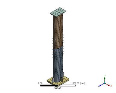

Chart-3: Loadv/sDeflectioncurvebyvaryingbolt diameter


Table-7: Ultimateloadandultimatedeflection
Ellipticalsteeltubularcolumnwithdeconstructablesplice jointismodeledusingsquaresteel tubularasbasemodel. Areaofsteelis8424mm2.Hencethemajoraxisofelliptical column is 340mm and minor axis is 200mm. Material propertiesofellipticalcolumnandspliceplatearesimilarto squaresteeltubularcolumn ModellingisdoneusingANSYS DesignModeler.
3.4 Effect of axial loading by varying bolt pattern
Boltpatternisvariedwith64,48and32numbersofbolt.
Fig
4.1 Cyclic testing
:Finiteelementmeshing
Chart-4: Loadv/sDeflectioncurvebyvaryingbolt pattern
Fig-10:1)Totaldeformation2)equivalentplasticstrain
Chart-5: Loadv/sDeflectioncurvebyvaryingsplice thickness


Table-9: Ultimateloadandultimatedeflection
Fig-11:Hysteresiscurveobtainedaftercyclicloadingtest


5. Effect of axial loading on elliptical steel tubular column with deconstructable splice joint.

Similartosquaresteeltubularcolumnwithdeconstructable splice joint,axial testing is done for elliptical crosssection considering the four parameters namely splice thickness, splicelength,boltdiameterandboltpattern.
5.1 Effect of axial loading by varying splice thickness
Spliceplateofthickness14mm,12mm,10mm,8mmand6mm are variedandtested.
5.2 Effect of axial loading by varying splice length
Spliceplateoflength785mm,685mmand585mmaretested underaxialloading.
Chart-6: Loadv/sDeflectioncurvebyvaryingsplice length
Table-10: Ultimateloadandultimatedeflection
Ultimateloadandultimatedeflection
5.3 Effect of axial loading by varying bolt diameter
Boltdiametersarevariedfrom24mm,22mm,20mm,18mm and16mm
6. Interpretation of results

Table-13: Underaxialloading
Chart-7: Loadv/sDeflectioncurvebyvaryingbolt diameter Table-11: Ultimateloadandultimatedeflection


Table-14: Undercyclictesting
5.4 Effect of axial loading by varying bolt pattern
Boltpatternisvariedwith64,48and32numbersofbolt.
Chart-8: Loadv/sDeflectioncurvebyvaryingbolt pattern
Research has been not been done so far by changing the splice and bolt parameters on square and elliptical cross sectionsofsteeltubularcolumnswithdeconstructablesplice joint. Square cross section shows maximum load carrying capacityof3412kNunderaxialloadingcomparedtoelliptical section. The structure can withstand up to 12.057mm deflectioncomparedtoellipticalsectionwhichcanwithstand only 8.2029mm.Hence more ductility is shown by square section. The steel tubular columns with deconstructable spliceconnectionwithmaximumloadgivegreaterstrength. Squaresectionshavealargermomentofinertiathantubular sections. Thismeans thata square sectioncan offer better bending and torsion resistance for a given cross sectional area, making it structurally efficient. When compared to tubular sections, square sections frequently have simpler connectiondetails.Thesimplicityoflinkingandconnecting squarepiecestootherstructuralpartsismadepossibleby theirstraightedges,whichalsohelptosimplifydesignand construction.Forsquare column cyclic loading test almost gavesameresultsobtainedfromexperimentwith0.8%error and storey drift of 2.44. Maximum bending moment of 251.77kNmandstoreydriftof4.1wasobtainedfromANSYS software.3-D finite element models were developed and tested for cyclic loading for elliptical cross section which
showedmaximummomentof 557.58kNmwith3%drift.As per FEMA protocol the structure is seismically stable if it takesabout2-4%ofdrift.Hencesquareandellipticalcross sectionscanwithstandseismicaction.Fromtheparametric study conducted on square cross section we can conclude thatsinceitisasymmetricsection,higherstrengthcaseis always shown by the structure with maximum thickness, length, diameter and number of bolts. Overall structural performanceisshownbycolumn.When theseparameters are reduced load carrying capacity is also reduced. For elliptical cross section(being an unsymmetrical section)maximum strength case is shown with higher thickness,diameterandnumberofbolts.Splicelengthof685 showsmoreloadcarryingcapacitythan785mm.Undercyclic stresses,steelcolumnsmaysufferprogressivedeformation includinglocalbucklingandstiffnessloss.
REFERENCES
[1] Ataei, A., Bradford, M. A., Valipour, H. R., & Liu, X.: Experimentalstudyofsustainablehighstrengthsteelflush end plate beam-to-column composite joints with deconstructable bolted shear connectors Engineering Structures, 123,124-140(2016).
[2]Cai,Y.,Quach,W.M.,Chen,M.T.,&Young,B.:Behavior and design of cold-formed and hot-finished steel elliptical tubular stub columns.Journal of Constructional Steel Research,156,(2019).
[3] Chen, M. T., & Young, B.: Material properties and structural behavior of cold-formed steel elliptical hollow sectionstubcolumns.Thin-WalledStructures, 134,111-126, (2019).
[4]Fan,J.,Yang,L.,Wang,Y.,&Ban,H.:Researchonseismic behaviour of square steel tubular columns with deconstructablesplicejoints.JournalofConstructionalSteel Research, 191,107-204(2022).
[5] Fan, S., Xie, S., Wang, K., Wu, Y., & Liang, D.: Seismic behaviourofnovelself-tighteningone-sideboltedjointsof prefabricated steel structures.Journal of Building Engineering,56,104-823(2022)
[6] Liu, X. C., He, X. N., Wang, H. X., & Zhang, A. L.: Compression-bend-shearing performance of column-tocolumn bolted-flange connections in prefabricated multihigh-risesteelstructures.EngineeringStructures,160,439460(2018).
[7] Liu, X. C., Tao, Y. L., Chen, X., & Chen, M. L.: Seismic performance of bolted flange splicing joints for CFST columns.JournalofConstructionalSteelResearch,196,107412(2022).
[8]Pongiglione,M.,Calderini,C.,D'Aniello,M.,&Landolfo,R.: Novelreversibleseismic-resistantjointforsustainableand
deconstructable steel structures.Journal of Building Engineering,35,(2021).
[9]Uy,B.,Patel,V.,Li,D.,&Aslani,F.:Behaviouranddesignof connectionsfordemountablesteelandcompositestructures. InStructures9,1-12(2017).

[10]Wang,W.,Li,M.,Chen,Y.,&Jian,X.:Cyclicbehaviorof endplate connections to tubular columns with novel slipcriticalblindbolts.EngineeringStructures,148,(2017).
[11]Ye,J.,Mojtabaei,S.M.,Hajirasouliha,I.,&Pilakoutas,K.: Efficient design of cold-formed steel bolted-moment connections for earthquake resistant frames.Thin-walled structures,150,(2020).
[12]Wang,Y.Q.,Zong,L.,&Shi,Y.J.:Bendingbehaviorand design model of bolted flange-plate connection.Journal of ConstructionalSteelResearch,84,1-16(2013).
