Seismic Behavior Of Double Steel Plate Composite Wall Under Cyclic Loading
Dr. Suchita K. Hirde1 , Anjali S. Ramteke21Professor And Head, Applied Mechanics Department, Government college of Engineering, Amravati, Maharashtra, India
2P.G. Student, Structural Engineering, Government College of Engineering, Amravati, Maharashtra, India
Abstract - Double steel plate composite walls (DSPCWs) have gained significant attention in the construction industry due to their exceptional seismic resistance and high ductility. However, the influence of key parameters such as aspect ratio and tie-stud spacing on the cyclic loading behavior of DSPCWs has not been comprehensively investigated. In this study, ABAQUS software is employed to analyze the effects of aspect ratio and tie-stud spacing on the hysteresis response, stiffness and strength degradation, and ductility of DSPCWs subjected to cyclic loading. The analysis is conducted in finite element analysis software ABAQUS CAE of DSPCW models, considering various aspect ratios and tie-stud spacing configurations. The aspect ratio is found to have a significant impact on the hysteresis response, strength degradation, and stiffness deterioration of the walls. Lower aspect ratios tendto promote greater energy dissipation, resulting in enhanced ductility but also increased strength degradation. Similarly, the tie-stud spacing is shown to influence the stiffness and strength degradation, with smaller spacing leading to improved performance.
Key Words: Composite Wall, Cyclic Load, Tie Bar, Steel Plate, Hysteretic Behavior, Stiffness, Strength Degradation.
1. INTRODUCTION
Doublesteelplatecompositewallconsistsoftwosteelplates connected with each other by tie bar and filled with a concrete infill, resulting in a composite section that can withstanda varietyofloadingconditions.Oneofthemost commontypesofloadingthatthesewallscanfaceiscyclic loading,whichinvolvestherepeatedapplicationofloadsin oppositedirections.Cyclicloadingcansignificantlyaffectthe structuralintegrity ofsteelplatecompositewalls,makingit importanttounderstandtheirbehaviorundertheseloading conditions. One of the most primary advantages of using DSPCW is its ability to withstand high loads and stresses. Thismakesitidealforuseinhigh-risebuildings,wherethe weight of the structure and the forces from wind and earthquakes can place significant stress on the building's walls. DSPCW is a highly versatile but durable structural system that offers numerous benefits, including high
strength, durability, and resistance to external forces. Its easeofinstallationandcustomizationmakeitanattractive option for construction projects of various sizes and applications.
2. NUMERICAL ANALYSIS
InABAQUS/CAEfiniteelementanalysissoftware,sixDSPCW specimensweredeveloped
Table -1: DetailsofSpecimens
DSPCW- Double Steel Plate Composite Wall, AR-Aspect Ratio, S- Tie Stud Spacing
3.1 FINITE ELEMENT MODELLING OF SPECIMENS AND ANALYTICAL STUDIES

3.1.1 Parts and elements of the model
The finite element model was created including steel face plates,topandbottomplates,sideplates,shearstuds,and infillconcreteasshowninfigure3.1andisometricviewof DSPCWAR-1,2,3isshowninfigure3.2.
3.1.2 Assembling of parts and contact properties

In ABAQUS, assembling of parts refers to the process of joiningmultiplepartstogethertocreateasinglemodel In addition to assembling, contact properties are also an important aspect of finite element analysis in ABAQUS.to neglect the motion between two surfaces tie constraint is used. For the tie bar which is embedded in concrete “Embeddedregion”constraintsareused.

3.1.3 Boundary conditions
Theencastreboundaryconditionconstrainsisused.allthree displacementdegreesoffreedom(DOF)ofthebottomsideof thesteelsupportswererestrained.
3.1.4 Meshing
A‘lineareightnoddedbrickelement’typeofmeshing60mm wasprovidedtoobtainresultsveryaccuratelyasshownin figure3.3.
3.1.5 Loading
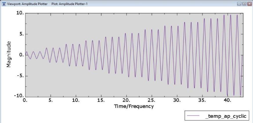
TheRP position islocatedatthe top ofthespecimen. The prescribed loading was achieved by using the amplitude functionatRPasshowninfigure3.4.
Steel plate composite wall, uses two steel faceplates of thickness10mmandgradeofsteelasFe250,Tierodisalso aconnectionmemberthatconnectsthetwofaceplatesand maintainsbondingbetweensteelandconcrete,here16mm diameter,Fe250steeltierodwasused.ForconcreteM50 gradeisusedshownintable3.1.


4. PERFORMANCE ANALYSIS

4.1 Failure mechanism
Commonfailuremodesincludesteelplatefracture,concrete crushing,shearfailureattheplate-concreteinterface,and excessive deformations. The damage process under cyclic loadingcanbesimplifiedasbeingcomposedofthreemajor stages:theelasticstage,theyieldingdevelopingstage,and thefailurestage.
a) Repeated cyclic loading can lead to progressive deteriorationofthedoublesteelplatecompositewallover time. Fatigue damage can accumulate as the structure undergoesrepeatedloadingcycles,resultingintheinitiation andpropagationofcracksasshowninfig.4.1.
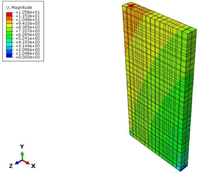
b) The initial stiffness of the wall decreases as the steel plates yield, and the concrete infill undergoes micro cracking.Thewallsfirstsufferedfrombucklingatthebaseof the right and left boundary corner and also at top left boundaryasshowninfigure4.2.

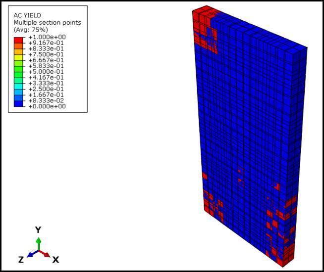
c) As lateral displacement increases, the existing local bucklingisdevelopedandisaggravatedasshowninfigure 4.3.Itwaslocatedmostlyatthetopofthewall.
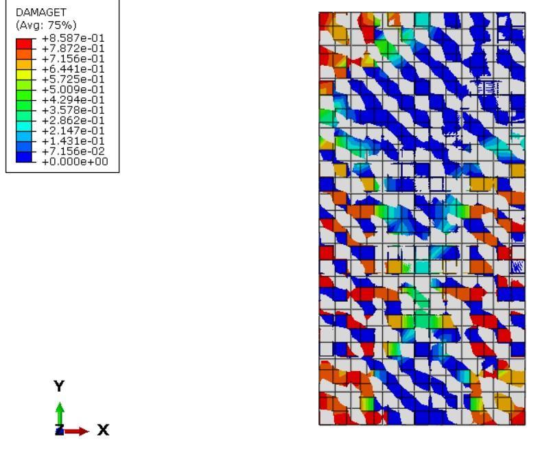
d)Ascyclicloadsareapplied,sheardeformationsinduced cracking and separation at the interface. Diagonal tension crackingisobservedasshowninfigure4.4.
5. RESULTS OF FINITE ELEMENT ANALYSIS:
5.1 Hysteretic behavior in load deformation form
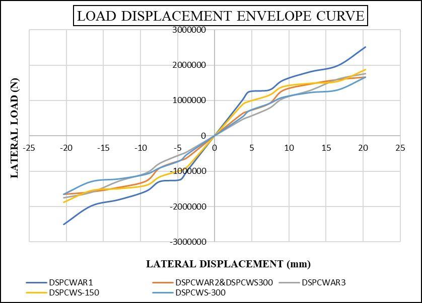

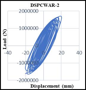
The hysteresis curve shows the energy dissipation and deformation characteristics of the material under cyclic loading.Thehysteresiscurveforahigheraspectratiowallis exhibitinglargerloops,indicatinggreaterenergyabsorption capacity.Thehysteresiscurveforaloweraspectratioasin figure5.1wallshowssmallerloops,indicatinglowerenergy absorptioncapacity.Thelateralloadcarryingcapacityofall sixwallisshowninfigure5.2
5.2 Stiffness and strength degradation
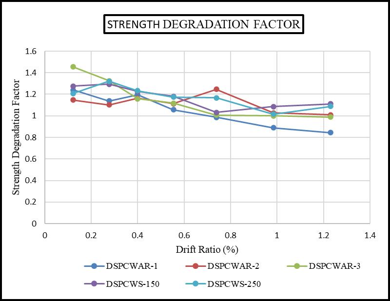
A strength degradation factor ���� was calculated using Eq. (1), …..(1) Stiffness����iscalculatedbyusingequation(2), …..(2)
wherePj+andPj-aremaximumpushandpulllateralloadat theJthloadinglevelandΔj+andΔj-arelateraldisplacement correspondingtoPj+andPj-respectively.
From the figure 5.4 and figure 5.5, the lateral strength degradationincreaseswiththedecreasesinthedriftratio. DSPCWwithanaspectratio1showsthelargestiffnessthan DSPCW with tie stud spacing 150 mm have better performance. The DSPCWAR-3 shows less stiffness and strength.
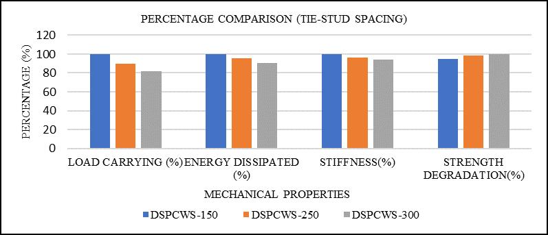

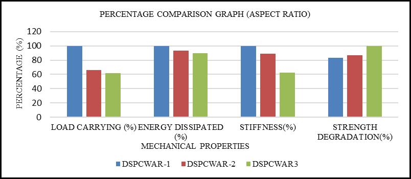
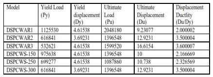
Ductility ratio μ is defined as the ratio of ultimate displacement to yield displacement. From table 5.2 the displacement ductility ratio for DSPCWAR-1 is smallest amongallthemodels.BiggerforDSPCWwithaspectratio3. Thestressinmodel1is20%lessascomparedtomodel3 and 20 % more as compared to model 2. As the tie-stud spacing increased from 150 to 300mm the stress value decreased 15 to 20 %. Figure 5.7 and 5.8 shows the percentage comparison between DSPCW specimen for aspect ratio and tie stud spacing for all mechanical properties.
5.3 Energy dissipation and displacement ductility
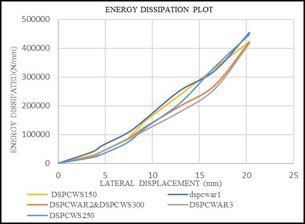
Energydissipationisnothingbuttheareaenclosedbythe hystereticloopatcorrespondingdeformationFromfig.5.6, energydissipationformodelwithaspectratio1is7to10% moreascomparedwiththemodelswithaspectratio2and3. Fortie-studspacingof250mmtheenergydissipationis7to 10%morefromanothertie-studspacings

6. CONCLUSION:
1) Thewallwithaspectratio1hadminimumdeformation thanwallwithaspectratio2and3. wallwith150mmtiestudspacingprovidedlesserdeflectionsthanwallwith300 mmtie-studspacinghencehavemoreloadcarryingcapacity.
2) Astheaspectratioincreased,thelateralstiffnessofthe wall decreased. A higher aspect ratio led to a larger wall section, results in enhanced strength and resistance to lateraldeformations.Asmallerspacingincreasedtheoverall stiffness of the wall, reducing the deflections and deformationsunderappliedcyclicload.
3) Thewallwithaspectratio3hadlargedeformationhence, theductilityofDSPCWAR-3ishigh.Aloweraspectratioand smallertie-studspacingcontributedtoimprovedductilityin a double steel plate composite wall subjected to cyclic loading.
4) The wall with lower aspect ratio and lower tie stud spacinghadlargeenergydissipationcapacity.
REFERENCES
[1] Jian-Guo Nie et al. (2013), “Experimental study on seismic behaviour of high-strength concrete filled doublesteel-plate composite walls”, Journal of ConstructionalSteelResearch, http://dx.doi.org/10.1016/j.jcsr.2013.05.001
[2] FeimingJetal.(2013),“Seismicbehaviourofsteeltube–double steel plate–concrete composite walls: Experimental tests”, Journal of Constructional Steel Research,http://dx.doi.org/10.1016/j.jcsr.2013.03.011
[3] Gao, X., & Han, L. (2016). “Seismic performance of double steel plate composite shear walls”, Journal of ConstructionalSteelResearch,119,53-61.
[4] Wu,Q.,&Chen,B.(2015).“Cyclicbehaviourofdouble steelplatecompositewallswithwebstiffeners”,Journal ofConstructionalSteelResearch,115,307-319.
[5] Hong-SongHuetal.(2016),“SeismicbehaviourofCFSTenhancedsteelplate-reinforcedconcreteshearwalls”, JournalofConstructionalSteelResearch,119,115-176.
[6] Xu-Lin Tang et al. (2018), “Experimental study on seismic behaviour of an innovative composite shear wall”, Journal of Constructional Steel Research, https://doi.org/10.1016/j.jcsr.2018.05.003
[7] El-Tawil, S., Bruneau, M., & Whittaker, A. (2003). Experimental and analytical study of steel-plate composite shear walls. Journal of Structural Engineering,129(8),1061-1071.
[8] Lin Chen et al. (2015), “Seismic behaviour of double steel plate–HSC composite walls”, Engineering Structures, http://dx.doi.org/10.1016/j.engstruct.2015.08.017.
[9] Behnam,B.,&Darvish,A.(2017).Seismicbehaviourof steel plate composite shear walls with and without openings.JournalofConstructionalSteelResearch,131, 94-105.
[10] Zhao, X. L., & Zhang, X. X. (2014). Experimental and numericalinvestigationofsteel-platecompositeshear walls with vertical boundary elements. Journal of ConstructionalSteelResearch,99,94-104.
[11] Hadi Kenarangi et al., (2021) “Cyclic behaviour of cshapedcompositeplateshearwalls – Concretefilled”, Engineering Structures, 226, https://doi.org/10.1016/j.engstruct.2020.111306
[12] Soheil Shafaei et al., (2021), “Cyclic Lateral Loading Behaviour of Composite Plate Shear Walls/Concrete Filled”, J. Struct. Eng., 2021, 147(10): 04021145, https://doi.org/10.1061/(ASCE)ST.1943-541X.0003091
[13] HongsongHu,etal,(2012),“Seismicbehaviourofsteel plate-concretecompositeshearwalls”.
[14] ZhenfengHuangetal.(2022),“Cyclicbehaviouroflow shear-span ratio dovetailed profiled steel–concrete compositeshearwalls”,JournalofBuildingEngineering, https://doi.org/10.1016/j.jobe.2022.105094
[15] Jiang,W.,&Guo,L.(2018).Cyclicbehaviourofbuckling restraineddoublesteelplatecompositewalls.Journalof ConstructionalSteelResearch,143,41-50.
[16] YikangLietal.(2020),“CyclicBehaviourofCorrugated Double-Skin Composite Walls with Different Aspect Ratios”, Journal of Structural Engineering, https://doi.org/10.1061/(ASCE)ST.1943-541X.0002783
[17] Wang,H.,Cao,W.,&Chen,W.(2020).Experimentaland analytical studyonseismic performance ofsteel plate composite shear walls with circular web openings. JournalofConstructionalSteelResearch,166,105938.
[18] Li Jie et al. (2016), “Experimental behaviour of innovative T-shaped composite shear walls under inplane cyclic loading”, Journal of Constructional Steel Research,http://dx.doi.org/10.1016/j.jcsr.2016.01.008
[19] Li, Z., Zhang, W., & Li, J. (2017). Experimental and numerical study on behaviour of double steel plate compositeshearwallswithintermediatesteel-concrete layer.JournalofConstructionalSteelResearch,130,7585

[20] Amer Hassan et al (2022), “Modelling of Cyclic Load Behaviour of Smart Composite Steel-Concrete Shear Wall Using Finite Element Analysis”, Buildings, https://doi.org/10.3390/buildings12060850 [21] ME 498CA1 Fall 2015 Introduction & Workflow, computational science and Engineering. https://davis68.github.io/me498cffa16/resources/alec01/workflow.pdf
[21] [22]YikangLietal(2022),“Cyclicbehaviorofdoubleskin composite walls with flat and corrugated faceplates”, Engineering structures, Volume 220, 111013
https://doi.org/10.1016/j.engstruct.2020.111013

