Design of 3x6 axial-slot array antenna on circular cylinder waveguide for 2.45 Ghz IOT applications
Traore Seydou 1 , Ouattara Yelakan Béranger2 , Siaka Fofana3 , Silue Dozohoua41Department of Sciences of the Structures of Material and Technology (SSMT), Technology Labs, Felix Houphouet Boigny university, Abidjan, Ivory Cost
2Department of Sciences of the Structures of Material and Technology (SSMT), Technology Labs, Felix Houphouet Boigny university, Abidjan, Ivory Cost
3Department of Sciences of the Structures of Material and Technology (SSMT), Technology Labs, Felix Houphouet Boigny university, Abidjan, Ivory Cost
4Department of Technological Resources, African School of Information Technology and Communication (ESATIC), Abidjan, Ivory Cost
Abstract - In this paper, a rectangular slot array antenna has been designed on a circular cylinder, shorted at both ends and fed by TE11 mode. The antenna operating at the frequency of 2.45GHz is proposed for a radio frequency identification (RFID) reader. RFID along with Zigbee, Bluetooth, and WIFI are connectivitytechnologiesforInternet of Things (IoT) networks. RFID technology is especially efficient for the detection of objects in the near field. Thus, the results of the simulations performed with the theoretical methodEC-FDTD underMatlabsoftware,werecomparedwith those obtained with the commercial software HFSS and the practical measurements. The array antenna consisting of 3x6 rectangular axialslotswasrealizedanditsS11parameterwas measured. The results of the practical measurements are in accordance withthe numericalresults.Theantennahasahigh gain of about 10 dBi, and a good reflection coefficient -25 dB at the frequency of 2.45 GHz. Furthermore, the mapping and evolution of the electric field determined at 10 cm from the antenna, shows that this antenna generates a strong and uniform electric field in the near field area around the cylinder. Therefore, this antenna can be used to ensure capacitive coupling and good communication between the reader antenna and the tag.
Key Words: Array antennas, Slot waveguide, Circular cylindrical,Omnidirectional,Internet-of-things(IoT),Near field.

1. INTRODUCTION
To monitor physical objects when they are stable or in motion in various fields such as healthcare, urban infrastructure, transportation and energy, the Internet of Things (IOT) uses various technologies including radio frequencyidentification(RFID).
Thus, to meet various requirements with better identificationperformance,manytypesofRFIDsystemsare rapidlyemerging.Theseincludelowfrequency(LF,125-134 KHz), high frequency (HF, 13.56 MHz) and ultra-high frequency (UHF, 860-960 MHz and 2.4 GHz). Currently,
passive near-field RFID-UHF technology operating by inductive coupling is receiving a lot of attention for nearfield identification as it brings several improvements comparedtolowandhighfrequencyRFID(LF/HF).Indeed, thedetectionspeedandthevolumeofdataexchangedare higherinUHFthaninHF,themanufacturingcostofthetags issignificantlylowerthanthatofHFtags.ButUHFRFIDcan also operate in the near field through the electric field (capacitive coupling) and communicate in the far field throughelectromagneticwaves(EM).Oneofthelimitations of current RFID systems is that they do not work well at close range (near field). This near-field communication problemisduetoaninsufficientmagneticfieldproducedby the antenna of the reader and tag in UHF as well as poor impedancematchingatthetag.
It is therefore important to design new antennas that can function properly in these near-field communications. Severalworksdealingwithnearandfarfieldantennadesign have been published [1]-[2] and have focused on the inductivecouplingbetweenthereaderandthetagantenna viathemagneticfield.Inordertosolvetheaboveproblems, the configuration of a 3x6 slot array antenna cut on a cylindricalwaveguideisstudied.ItisfedinTE11modeata frequencyof2.45GHz
Indeed, an array of rectangular slots cut in the wall of a hollow cylinder seems to be a good configuration for omnidirectionalradiocoverage:itislessexpensive,simple tobuildandhasalmostnolosseswhenfedbyamonopole. Researchandpublicationsoncircularslotwaveguidesdate from the 1950s to the present day [3]-[11]. The study of radiationfromanaxialslotontoacylindricalconductorhas been widely published [4]-[6]. However, the papers [12][14]focusonarraysofaxialandcircumferentialslitslinearly arrangedonthecylindricalgenerator.Mostoftheseantenna characterisations are simulated on commercial software suchasHFSSorCST[14],[24]-[25].
ThefirstmentionoftheEC-FDTD(Equivalent-CircuitFinite DifferenceTimeDomain)methodappears,toourknowledge,
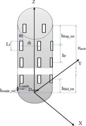
inthepublicationsofGwareketal[18]andCraddocketal [19]. The first implementations of the proposed EC-FDTD algorithm were made for a regular Cartesian mesh, as described in [20]-[21] and in more detail in [22]-[23]. Following Maxwell's equations, the appropriate EC-FDTD formulationisdirectlydeduciblefromitsdifferentialform (which is certainly constitutive of the conventional FDTD scheme) or from its integral form, the latter defining the starting point of our EC-FDTD scheme. This method has neverbeenusedformodellingcylindricalwaveguideslotted antennas.Theproposedantennaconfigurationisbasedon anarrayofaxialslotsarrangedlinearlyornon-linearlyalong thelength.Itconsistsofsix(6)ringsofthreeslotseach,i.e. eighteen (18) slots in total (see Figure 1). Indeed, the advantageofthree(03)slotsplacedat120°fromeachother onthesamering(orlevel)allowsustotheoreticallycover thedesired360°,toincreasethenumberofantennas(slots) of the array and therefore of radiating elements and to reducethesize(height)ofthecylinder.
2. MATERIALS AND METHODS

wide w=L10 ff .Inthedirectionoftheaxis,severalslots arespacedeachotherby 2 g .Thefirstslot,locatedatthe bottom of the cylinder is about inf_ 34fextgh comparedwiththelowerendofthecylinder.Whilethelast slotisatthetopof sup_ 4 fextgh comparedwiththe topendofthecylinder.Ateachcrown(or ring),thereare several slots spaced from 1 .()fguidenndr or fn representingtheangulardifferenceinradianbetween twosuccessiveslotsand 1 fortheangularpositionofthe firstslot.
Equivalent-Circuit (EC)FDTDhasseveraladvantagesover the classic FDTD. Since its update values are voltages and currents (as opposed to electric and magnetic fields), it allowsaneasyintegrationofelectroniccomponents,suchas forinstancediodesandtransistors,intothesimulation. In addition,itprovidesincreasedcomputationalspeedthanks to a reduced number of multiplications in the update equations [24]-[26]. Finally, it may be generalized to arbitrarydispersivemedia.
OpenEMS is a free source code used for the rigorous modelingoftheelectromagneticfield(EM)underMatlabor octave [15]. It is based on the equivalent circuit of finitedifference time-domain method (FDTD). The program designer is rigorously placed in the Matlab environment structure and its mesh. The mesh step selection appears especially important to get a good result. It is possible to visualize the structure from the AppCSXCAD graphical interface associated with Matlab. The basic EC-FDTD equationsarebasedontheclassicalFDTD.Wehave:
ThegeneralstructureFigure1oftheproposedconfiguration isacylindricalguideofcircularsectionofheight(Hguide,); radiusguide(rguide)andthickness. Thearrayofradiatingantennasshapedonthesurfaceofthe short-circuited cylinder at both ends is a set of small rectangular axial slots of length L=λ4 0 f and
ThediscretisationfromtheYEEscheme[14]leadsto:
Wherewehavethevoltageandcurrentcomponentsas following: xxxyyyzzz x xxyyzzyz
υ=ΕΔ,υ=ΕΔ,υ=ΕΔ i=H Δ,i=HΔ,i=HΔ
Then,equations(3)and(4)become: yyzzzyxxxx d i-in-1-i+in-1C υ+Gυ dt (5)
With: xx xx xx
εΑκΑ C=G= ΔΔ
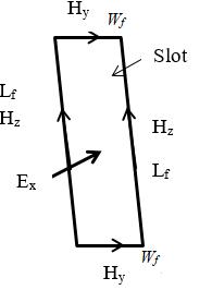
Whenweapplythecontourpathmodelofthenarrowslot [26]withintheslotsairgap,weobtainequation(11)derived fromequation(3).
And :
yyxxxyzzzz d υ-υn+1-υ+υn+1-Li-Ri dt (6)
With : zz zz XX
μΑσΑL=R= ΔΔ
t t nn-1 xx xx tt xxxx n-0,5n-0,5n-0,5n-0,5 nnnn yyxxxy n+0,5n-0,5n+0,5n-0,5 yyyy zz
tt tttt 2C-ΔG 2Δ υ=υ+ × 2C+ΔG2C+ΔG i-in-1-i+in-1 (7) tttt tttt

υ-υn+1-υ+υn+1= i-ii+i L+R dt2
8 tttt tttt
n-0,5n-0,5n-0,5n-0,5 yyzzzy nn-1nn-1 xxxx x
i-in-1-i+in-1= υ-υυ+υ C+GxΔt2
(9) tt tt
t t n+0,5n-0,5 zz yy tt zzzz nnnn tt yyxxxy
2L-ΔR 2Δ i=i-× 2L+ΔR2L+ΔR υ-υn+1-υ+υn+1 10
: Ampère’slawfor E yfyzfzff 0 x zy S Ηw-Ηn-1w-ΗL+Ηn-1L d ΑεΕ dt 11 ffLw s istheslotsurface The electromagnetic field in the slot are calculated by the expressions(12): t tt tt n-0,5 n-0,5 t f t nn-1 n-0,5n-0,5 0s zzy yy f z xx H-Hn-1×w Δ E=E-× εΑ H-Hn-1×L 12
Fig-2
-jβz ρ1c 2 c -jωμ Ε=ΑcosJkρe k ρ (13) '-jβz 1c c -jωμ Ε=ΑsinJkρe k (14) '-jβz 1c c -jβ = ΑsinJkρe Hρ k (15) -jβz 1c 2 c -jβ H= ΑcosJkρe k ρ (16) Where:
function of first kinds,
The electrical parameters of the proposed antenna are calculated baseonthetransmissionlinetheory.Theamplitudeof thereflectedvoltage( refv ) wave normalized totheamplitudeof the incident voltage ( incv ) wave is defined as the voltage reflection coefficient, S11:
we put the current i as a factor in expression (18) and then simplify, we obtain the expression:

v : Total voltage in the waveguide antenna : Total current in the waveguide antenna
Equation (17) can be expressed in another form:
Where,Z11istheCircuitinputimpedance
3. Results and Discussion
3.1. Simulation of different configurations under EC-FDTD
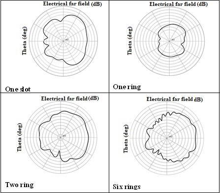
First, the antenna is modelled with EC-FDTD method programmedontheMatlabsoftwareforfourconfigurations ofslotsaspresentedinFigure2:
1) Oneslot
2) oneringofthreeslots;
3) tworingsofthreeslots;
4) Sixringsofthreeslots.
The results of simulations are used to find the optimum configurationsofslotsonthecylindricalcavityantenna in frequency band 2.45 GHz (i.e., high gain, bandwidth and return loss etc.). Then we compared the simulated parameterswithHFSSresults.
InTable1,thevaluesofthevariousparametersusedforthe antennageometryarerecorded.
TEZ is the wave impedance that relates the transverse electric and magnetic fields:
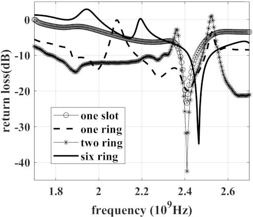
Figure3andFigure4respectivelyshowtheS11parameter simulation's results and of the radiation pattern of the differentantennas.
and k represent respectively the intrinsic impedance and the wave number in air material filling the waveguide.
TheS11characteristicsandradiationpatternsofdifferent configurations have been simulated with the EC-FDTD sourcecode.
Theresultsofthesesimulationsallowedustodeterminethe bandwidthsofthesedifferentantennasat-10dBiwhichhave beenrecordedinTable2.

Theincreaseinthenumberofslotssystematicallyleadsto an increase in the size of the antenna (we went from 135.85mmlengthfortheoneslotantennato645.95mmfor the18slotantenna).Therefore,themanualadaptationofthe
mesh size for each simulation does not allow us here to appreciate the effect of the increase of the slots on the bandwidth.Buttheseresultsshowthattheseantennascan indeedoperateatthe2.45GHzfrequency.
Concerningtheradiationpatterns,thesimulationresultsare in agreement with our assumptions. Their quasiomnidirectionalnaturefortheantennaarraysasshownin figure2willallowustocoverthe360o Nevertheless,wecan always increase the number of slots on the crowns to improvethisresult.
Slot ring
Bandwidth
Return loss
One slot 3% -11dBat2.45Ghz
One ring 13% -16.42dBat2.45Ghz
Two rings 2.71% -15.48dBat2.45Ghz
Six rings 4.2% -18.81dBat2.45Ghz
3.2. Comparative Study
Inthissection,wehavecomputedtheantennastructureand simulated under Matlab using openEMS source code that usesfinitedifferencetheory(EC-FDTD)asmodelingmethod oftheelectromagneticfield.
Theparametersconsideredforthestructuregeometryare those of table 1, more precisely those of six rings of slots resulting to eighteen (18) slots in total. The slots are well aligned by number of six (06) on each angular position. Figure 5(a) and Figure 5(b) show the numerical configurations and Figure 5(c) shows the picture of the antennamadeofaluminum.Theslotswereobtainedwithan automaticmachineofhigh precision. Thefolding machine made possible to obtain the rounded shape and the waveguideisshortedmanually.
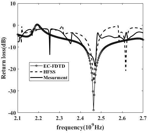
ThesimulationresultspresentedinFigure7showthatthe curveobtainedfromEC-FDTDoffersawiderbandwidththan thatobtainedwithHFSSandseemstobemoreinagreement withthepracticalmeasurement.Theobservedgapbetween numericalresultsandpracticalmeasuresarecertainlydue tomanufacturingdefects.
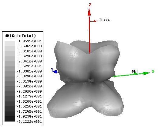
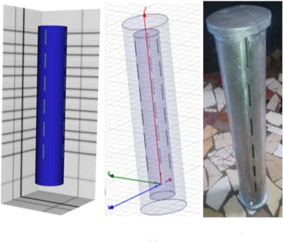
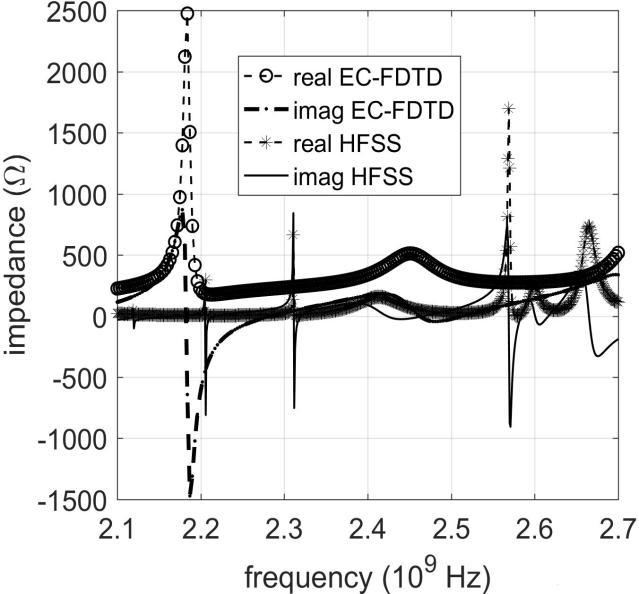
Figure6showsthatatthe
frequencyof2.45GHz, the input resistance is about 50 Ω while the reactance is zero,whichisidealforthechoiceofthematchingpoint.
TheKeysightreferenceinstrumentN9330Boperatinginthe frequencyrangeat25MHz-4GHz,allowedustorealizethe practicalmeasuresofthereflectionfeedbackS11.Theresult ofthesemeasurementsiscomparedtothenumericalresults inFigure7.

3.3. Near field survey for IOT (Internet of Things) applications

Thisstudyaimsatevaluatingtheelectricfieldcharacteristics ina10cmareaaroundtheantenna.Thus,wecouldobtain:
-Theelectricfieldmapping(fig-9)ataheightof10cmabove theantenna,
-ThelinearevolutioncurveoftheEfieldoveradistanceof 10cm(fig-10).
This curve shows that the electric field decreases progressivelyasonemovesawayfromtheantenna.There are two parts as far as the evolution of this curve is concerned:
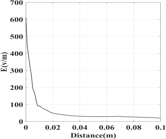
- Between [0 ;1cm] it decreases very quickly from 600v/mto100v/m
- Between[1cm;10cm]itdecreasesveryslowlyand is practically constant beyond 3cm with an approximatevalueof25V/m.
he mapping of the electric field and its evolution over a distanceof10cmshowsagooddistributionoftheelectric fieldinthenearfieldarea.
4. CONCLUSION
In this study, we have characterized circular cylindrical waveguide antennas consisting of an array of rectangular axial slots using three different methods. These are two numericalelectromagneticfieldmodellingmethods(HFSS andEC-FDTD)andpracticalmeasurementsperformedona fabricated prototype antenna. The size and particular locationoftheannularslotsonthewaveguidecontourseem to be very important for obtaining optimal results. Itwaspossibletoobserveanincreasinggainoftheantenna withthenumberofannularslots.
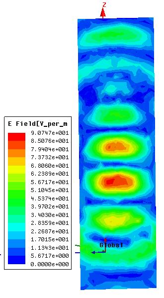
The electric field mapping obtained at a height of 10 cm abovethearrayantenna,showsareadingareaof64.(L)×34 (W)cm2 whichisfavorableforthedetectionofdipoletype tagsbycapacitivecoupling.
Butatthesametime,thereisanarrowingofthebandwidth which can be increased by choosing not to align the resonanceofallcomponents(slots)ofthesamecolumnon onepoint,butonseveral.Furthermore,thepracticalresults, consistent with the numerical results, show that the omnidirectionalantennacanoperatewithgoodgaininthe 2.4GHz frequency band. Also, the electric field mapping obtained at à distance of 10cm from the antenna shows a good electric field distribution in the near field area. Therefore,thisarrayantennabasedoncapacitivecouplings for near-field RFID applications can be used for goods tracking or supply chain management. But it can also communicate in the far field by means of electromagnetic (EM)waves.
REFERENCES
[1] B. Shrestha, A. Elsherbeni, L. Ukkonen, “UHF RFID ReaderAntennafornear-fieldandfar-field operations,” IEEEAntennas WirelessPropag.Lett,vol.10,Nov.2011,pp. 1274-1277.
[2] X.Qing,C.KhanGoh,Z.NingChen,“AbroadbandUHF near-fieldRFIDAntenna,” IEEETrans. AntennasPropag., vol.58, no.12, Dec.2010, pp. 3829-3838.
[3] G.Sinclair,“ThePatternsofSlotted-CylinderAntennas,” Proc. IRE, Vol. 36, pp.1487-1492, Dec. 1946
[4] S. Silver and W. K. Saunders, "The External Field ProducedbyaSlotinanInfiniteCircularCylinder,"Jour. Appl. Phys. Vol. 21, pp. 745-749, Aug. 1950.
[5] L.L.Bailin,“Theradiationfieldproducedbyaslotina large circular cylinder,” IEEE Trans. Antennas Propag., vol.3, no.3, pp.128–137, Jul. 1955
[6] S. Sensiper, W. G. Sterns, and T. T. Taylor (1952), “A furtherstudyofthepatternsofsingleslotsoncircular conductingcylinders,” Trans. IRE Prof. Group Antennas Propag, 3(1), 240–250.
[7] J.R.Wait,“ElectromagneticRadiationfromCylindrical Structures” , Pergamon Press, Inc., New York, NY, 1959.
[8] E.W.Wolff,AntennasAnalysis, John Wiley & Sons, Inc., USA, 1966.
[9] S. W. Lee and S. Safavi-Naini, “Asymptotic solution of surface field due to a magnetic dipole on a cylinder,” University of Illinois at Urbana-Champaign, Electromagnetics Laboratory Report n°. 76-11, 1976.
[10] S. W. Lee, S. Safavi-Naini, and R. Mittra, “Mutual admittance between slots on a cylinder,” University of Illinois at Urbana-Champaign, Electromagnetics Laboratory Report n°. 77-8, 1977.
[11] G. E.StewartandK.E.Golden,“Mutual admittancefor axial rectangular slots in a large conducting cylinder,” IEEE Trans. Antennas Propagat., vol. AP-19, pp. 120-122, 1971.
[12] L. Shafai. and E. M. Hassan (1981), “Field distribution and radiation field of finite axial slots on circular waveguides,”IEE Proc. Part H MicrowavesOpt.Antennas, 128(5), 263–267.
[13] D.H.ShinandH.J.Eom(2005),“Radiationfromnarrow circumferentialslotsonaconductingcircularcylinder,” IEEETrans.AntennasPropag.,53(6),2081–2088.

[14] D.H.ShinandH.J.Eom(2006),“Radiationfromnarrow axialslotsonaconductingcircularcylinder,” Radio Sci., 41, RS4005, doi:10.1029/2005RS003430
[15] L. Thorsten, R. Andreas, H. Sebastian and E. Daniel, “openEMS – a free and open-source equivalent-circuit (EC) FDTD simulation platform supporting cylindrical coordinatessuitablefortheanalysisoftravelingwave MRI applications,” Int. J. Numer. Model. 2012, doi: 10.1002/jnm.1875
[16] A.Taflove,S.Hagness,“ComputationalElectrodynamics: The Finite difference Time-domain Method,” 3rd edn. Artech House: Norwood, MA, 2005
[17] M.D.Pozar, Microwave Engineering 4th edn,JohnWiley &1ps03-vidmar
[18] W.K.Gwarek,“Analysisofanarbitrarily-shapedplanar circuit – a time-domain approach,” IEEE Transactions Microwave Theory and Techniques 1985; MTT 33(10):1067–1072
[19] I.J.Craddock,C.J.RailtonandJ.P.McGeehan.“Derivation and application of a passive equivalent circuit for the finite difference time domain algorithm,’’ IEEE Microwave and Guided Wave Letters 1996; 6(1):40–42
[20] A.Lauer,I.Wolff,“StableandefficientABCsforgraded mesh FDTD simulations,” IEEE MTT-S International Microwave Symposium Digest, Vol. 2, Baltimore, MD, 1998; 461–464.
[21] A. Lauer, I. Wolff, “A conducting sheet model for efficient”widebandFDTDanalysisofplanarwaveguides and circuits,” IEEE MTT-S International Microwave SymposiumDigest, Vol. 4, Anaheim, CA, 1999;1589–1592, doi:10.1109/MWSYM.1999.780262.
[22] A. Rennings, A. Lauer, C. Caloz, I. Wolf. “Equivalent Circuit (EC) FDTD Method for Dispersive Materials: Derivation,StabilityCriteriaandApplicationExamples,” Springer Proceedings in Physics, vol. 121. SpringerVerlag: Berlin, 2008; 211–238.
[23] A. Rennings, “Elektromagnetische zeitbereichssimulationen innovativer antennen auf basis von metamaterialien,” PhD Thesis, University of Duisburg-Essen,September2008.
[24] I.I. Ahmed, A.E. Taha “A cylindrical wideband slotted patchantennaloadedwithFrequencySelectiveSurface for MRI applications” . Engineering Science and Technology, an International Journal 20 (2017) 990–996
[25] R. Joseph, S. Nakao, and T. Fukusako,“Circcular slot antennasusingL-shapeprobeforbroadbandecircular polarization,” Progress in Electromagnetics Research C, Vol. 18, 153-168, 2011
[26] A.Rennings,S.Otto,A.Lauer,C.Caloz,andP.Waldow. “AnextendedequivalentcircuitbasedFDTDschemefor theefficientsimulationofcompositeright/left-handed metamaterials,”Proc.oftheEuro.Microw.Assoc.,vol.2, no.1,pp.71–82,March2006.
[27] A.Rennings,S.Otto,C.Caloz,A.Lauer,W.Bilgic,andP. Waldow. “Composite right/lefthanded extended equivalent circuit (CRLH-EEC) FDTD: stability, dispersion analysis with examples,” Int. J. Numer. Modell.,vol.19,no.2,pp.141–172,March2006.
[28] Taflove,A.,K.R.Umashankar,B.Beker,F.Harfoush,and K. S. Yee, "Detailed FDTD analysis of electromagnetic fieldspenetratingnarrowslotsandlappedjointsinthick conductingscreens,"IEEETrans.AntennasPropagat.,Vol. 36, 1988, pp. 247-257.

