International
Research Journal of Engineering and Technology (IRJET)


International
Research Journal of Engineering and Technology (IRJET)

Abstract - The effects of vertical acceleration of the ground on flat slab building are presented in this paper. In thecurrent environment, most design standards, including IS 1893-2016, recommend that the vertical acceleration element of an earthquake be designed as 2/3 of the horizontal. During recent quakes, the vertical element of ground motion was discovered to be greater than the horizontal element. It is consequently vital to investigate structural reaction in this sort of earthquake, where the vertical element's peak ground acceleration (PGA) may reach two-thirds of the horizontal element. Time history analysis was done in this study utilising 5 unscaled seismic data. To account for the influence of vertical ground vibrations, 5 various structural systems were investigated, including adrop panel,shearwalls,andthreeflat plates of varying thickness. Variations in several parameters such as axial force for column at several locations in building, punching shear at the junction of slab & column, and deflection of slab have been examined. The results of the calculations demonstrate that vertical ground movement has a significant impact on the flat slab structure in regards to axial force variations, punching shear, and deflection of slab.
Key Words: flat slab, flat plate, vertical ground motion, vertical earthquake motion, vertical PGA, response of flat slab, time history analysis
Thereinforcedconcreteflatslabtechniqueisbeing used extensively for residential and commercial development in various regions, including high seismic zones.Flatslabisfashionableandeasytoconstruct.Italso helps to maximise the height between the ceiling and the floor.
1. FlatSlabswithoutdropandcolumnhead.
2. FlatSlabswithcolumnhead.
3. FlatSlabswithdrop
4. FlatSlabswithdropandcolumnhead
Duetoitslowlateralstiffness,flatslabswobblesignificantly duringseismicevents,andthemostdangerousfailureinflat slabs is punching shear failure. If this occurs, the surrounding connections must be able to handle and redistributed pressures else it might cause a progressive failureofthestructure.
Duetothebeliefthatverticalaccelerationisoften smallerthanhorizontalacceleration,verticalgroundmotion has received less study. The vertical component of the groundmotionwasfoundtobegreaterthanthehorizontal componentduringthemostrecentearthquakes.Mostdesign codes, including IS-1893 (2016), accept Newmark and Hall's (1982) recommendation that the design vertical spectrumshouldbe2/3ofthedesignhorizontalspectrum.
Within30kmofthesource,theV/Hratioiscrucial, accordingto Papazoglou and Elnashai (1996) (1), andthe 2/3ruleisfoundtobeonthecautioussideforeventsthat occurclosetothesource.
Nipan Bhandar Kayastha and Rama Debbarma (2016) (2) performed analysis on G+3 building by SAP 2000.TheyconsideredseismiczoneVwithsoftsoilstrata. Theychose5differentstructural configurationsconsist of conventional RC frame structure, flat slab with dropped, column head & shear wall. Flat slab with shear wall at periphery performs batter that general RC frame. It also givesmaximumbaseshearcomparetoothermodels.Story displacement,Storydriftareminimuminflatslabwithshear walls.Naturalperiodisalsoveryless
Further,astudyonverticalgroundmotionandits impactonengineeredstructuresby Bipin Shrestha (2009) (3) found that the current design process could have catastrophicresults.Itisadvisedthatsiteslocatedwithin20 kmofthemainactivefault bedesignedtoaccountforthe combined effectof horizontal andvertical ground motion. TheV/Hratiosfornear-sourceseismiceventscanbehigher than2/3.Theprimaryimpactoftheverticalgroundmotion onthestructureisto putmoreaxial strainon thevertical loadbearingelement.Whenaverticalmotionwithsimilar amplitudetoahorizontalmotionoccurs,itisseenthatthe axialforceistypicallygreaterthantheequivalenttransverse loading.Itisalsonotedthatvariationofaxialforceismore onupperfloorratherthanlowerfloor.
fluctuationreducesshearcapacityandraisesthepossibility for shear failure as the Vertical to horizontalratioand lengthratiorise.
The seismic reaction of Reinforced Concrete structure subjectedtobothgroundmovementsobservedduringthe 2009L'Aquila(Italy)quakewasresearchedby L Di Sarno, A.S. Elnashai, and G. Manfredi (5). Four documented ground accelerated movements were used in a nonlinear dynamicanalysis.Accordingtothefindingsoftheinelastic dynamic studies, an average rise in column compression loadvariesbetween175%.Theyusedtimehistoryanalysis toexaminetheinfluenceofverticalseismicvibrationsona7storyframebuilding.WhentheV/Hratiois1.31,theaxial forceoftheinternalcolumnsdecreases1.3timescompared tothegravityload,indicatingthattensionforcedeveloped. Furthermore,whenjustlateralgroundmotionwasapplied, theplastichingesweremostlyfoundneartheframe'sbeam ends. However, when combined horizontal and vertical ground movement wereapplied, the column hinges significantlyincreased,particularlytheplastichingesatthe intermediatefloorcolumns.

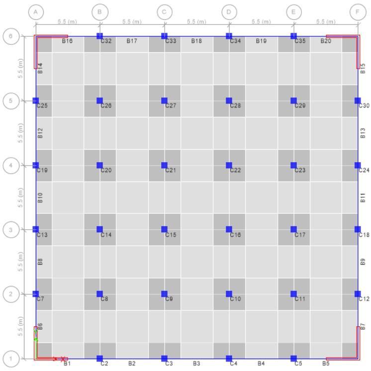
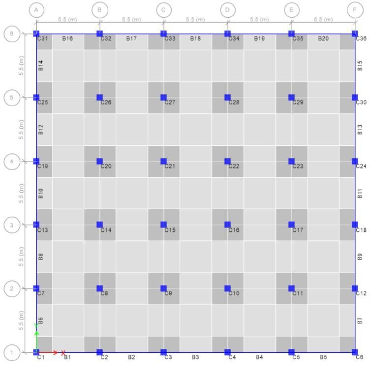
Inthisstudy,threepossiblestructuralconfigurations flatplate,flatslabwithdrop,andflatslab dropwithshear wall were taken into consideration for each of the two buildings, G+7, G+10. Three alternative Length to Depth ratios15,20,and25aretakenintoconsiderationfortheflat plate structural system for determining the impact of slab thickness on punching shear and vertical acceleration. All modelsincludesbeamsatperimeter toreducetheamountof punchingshear stressatslab-column intersections.Forall structures, the storey height is maintained to 3 metres.
The following factors were evaluated while selecting ground movement records: (1) Seismic magnitude greater than6 (2)Epicentredistancelessthan30kM,(3)Verticalto Horizontalratio should be greater than2/3(4) non-pulse groundmovementdata.Weinvestigated5unscaledseismic ground movements after screening out earthquake recordings from the strongmotioncenter &NGA-West2 database using these criteria, as indicated. As a result, we examined around 50 models for various vertical ground movements.ThelineartimehistoryapproachandETABSv17 wereusedtoanalyseallbuildingssubjectedtobothvertical andhorizontalgroundmotionacceleration.
Table -2: gravityloadsandmaterialgrade Gravity
*EP=epicenterdistance,M=Magnitudeofearthquake,Hor1=Long.PGA,Hor2=Trans.PGA,Ver=VerticalPGA
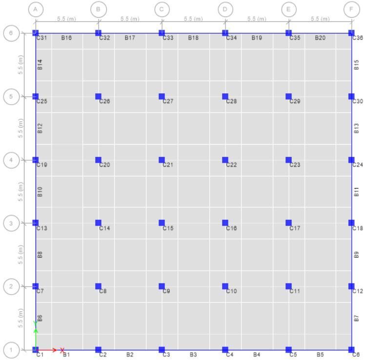
For5chosengroundmotionrecords,alineartime historyanalysisiscarriedoutandappliedto(5+5)various buildings. G+7 and G+10 will be used to denote building heightinthestudy,whileD,SW,LD15,LD20,andLD25will denotestructuralsystemdropandshearwall,respectively.
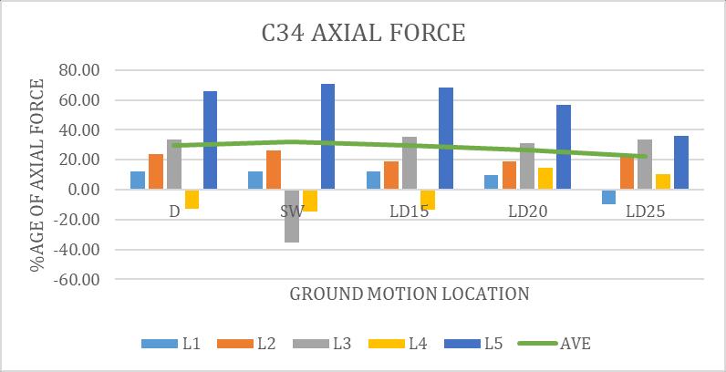

Above are charts 3 to 5 for G+7 building. We chose three columns to illustrate the consequence of axial force in a columncausedbyverticalaccelerationcomparetogravity load. C34is situated atouter perimeter, C28is the middle column, and C22is the interiorcolumn. In all models, the highestaxialforceisrecordedintheloweststory;however, certain columns encountered axial tension loads greater thanaxialcompression.Similarly,belowcharts6to8arefor G+10building.
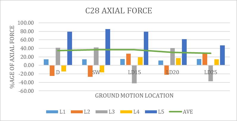
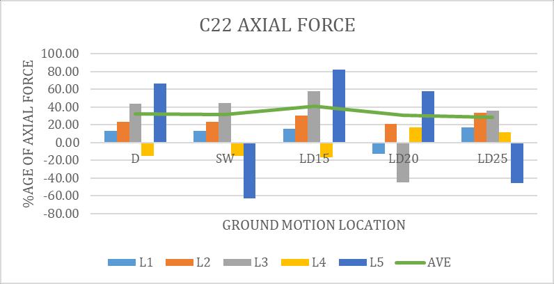
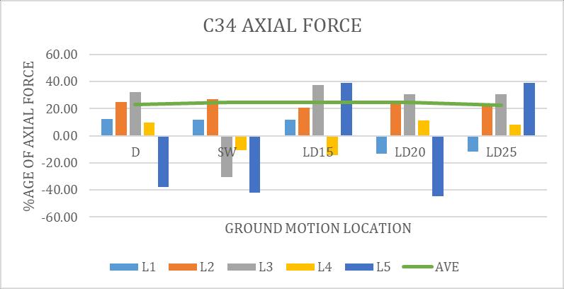
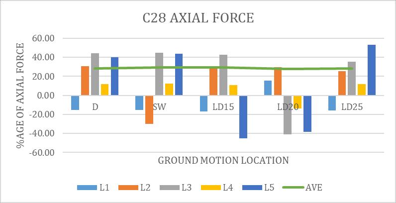
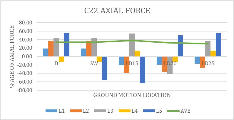
Maximum axial force due to gravity is 3441KN & 4780KN respectively in G+7 & G+10 building. Whereas Maximum axialforceduetoverticalacceleration2827KNcompression &1721KNastensioninG+7buildingwhereas2600KNas compression & 3028KN as tension in G+10 building
Maximum fluctuation is occurred in G10_LD15_L5 L5 indicatedCHI-CHITaiwanlocation.IthasV/Hratioof1.02. L3indicatedUTTARKASHIIndialocation.ithasV/Hrationof 1.19thoughL5hasmorefluctuationincolumnaxialforce thanL3.
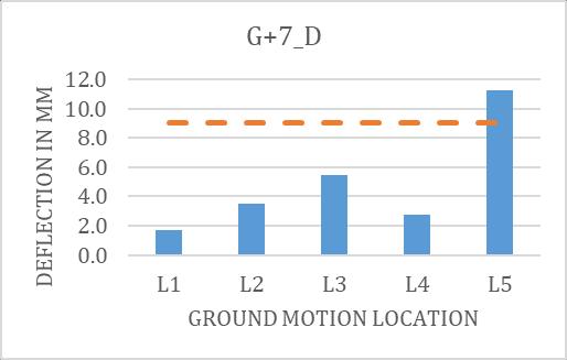
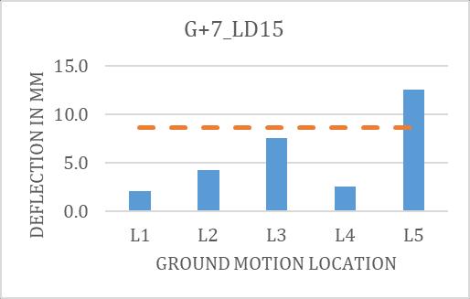
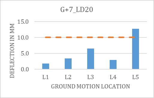
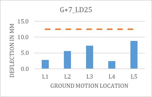
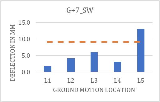
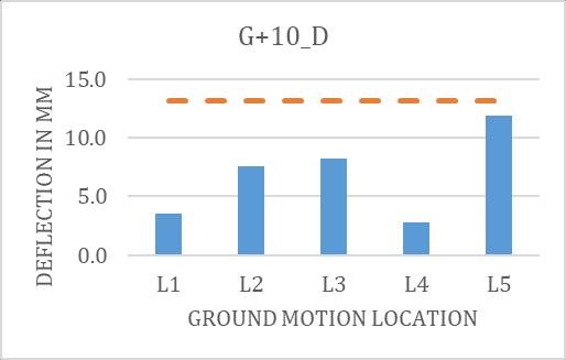
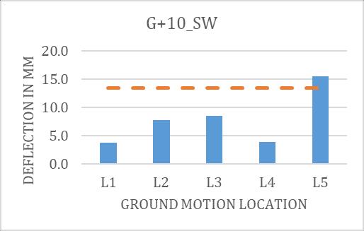
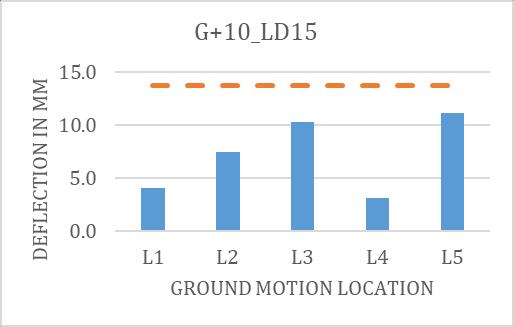
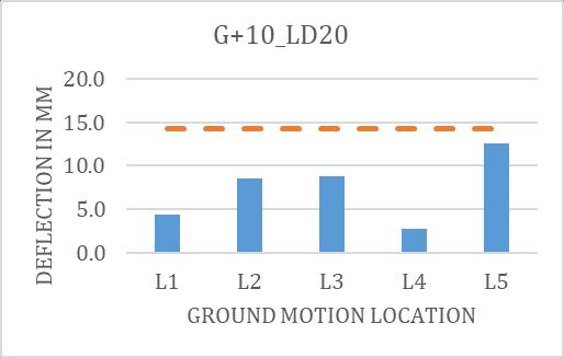
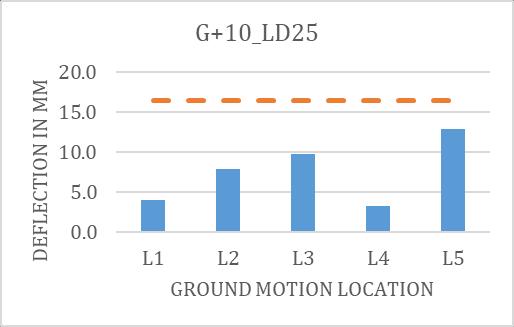
Theseismicimpactonaflatslabbuildingisshown byslabdeflection.Theslabdeflectionappearsgreatestnear thecentreoftheslabforallearthquakerecordsandmodel. Duetothecolumn'saxialcompressing/Tensioningeffect,the overalldeflectionoftheslabisdeeperonthetopfloorand progressively decreasing in the story below. As a consequence, the top mostslab result is shown in figures belowforvariousstructuralsystems.Belowchartindicate absolutevalueofdeflectionignoringhoggingorsagging.In belowchartsdeflectionduetoverticalcomponentisshown as bars where deflection due to gravity load is shown as dottedline.

Ascanbeseeninthefigures,inonecase,thedeflectionofthe slab owing to vertical ground motion is greater than the deflection caused by gravity loads. The maximum slab deflectioncausedbyverticalaccelerationinG7_SWis13mm, whereasthemaximumdeflectiongeneratedbygravityloadis 9.1mm in G7_SW & 12.5mm in G7_LD25. As a result, the overall deflection will be 22.1mm, which is substantially greater than the limit prescribed (L/250) inIS 456. This displacementmaycausenon-structuralpartstobedamaged andslabstiffnesstodeteriorate.Whendropsarecomparedto with&withoutshearwalls,deflectionincreasesindropwith shear wall. It isshowing that shear walls won't be able to regulatedeflectionduetoverticalmotion.Incomparisonto slabthickness,themaximumdeflectionofLD15,LD20,and LD25is11.1mm,12.6mm,and12.9mm,respectively,when using L5, suggesting that deflection due to vertical componentwouldriseasslabthicknessdecreases.Sameas G+7seebelowchartforslabdeflectionforG+10building.

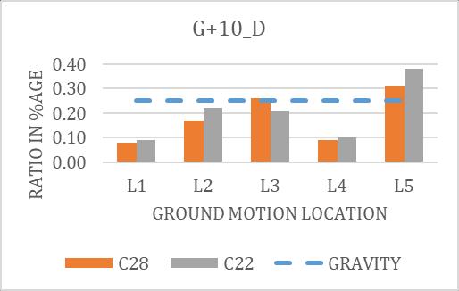
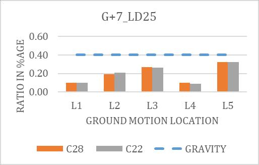
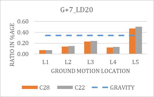
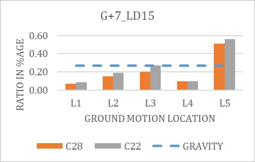
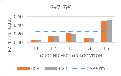
FailureduetoPunchingshearisthemostcatastrophicform offailureinflatslabs;itisharmfulsincetherearenoobvious symptomsoffailurepriortobreakdown.Verticalearthquake accelerationcangreatlyenhanceboththeverticalshearand slab rotationconveyed by a slab-column junction. As we haveshown,thelargesteffectofverticalmotionisfoundin the interiorcolumn, and the maximum effect of punching shear is found at C22column. The hiddenline in charts representspunchingshearcausedbygravityloads.Punching shear failure produces comparable results to slab deflections. The maximum shear stress ratiocaused by verticalearthquakecomponentis0.45&0.52intheG+10& G+7SWbuildingwhereasduetogravityitis0.25.Flatslab withdrop&dropwithshearwallhavealmostsamevaluein gravity but flat slab with shear wall have more punching shearvalue.Outof5groundmotionlocation,2locationhave valuesmorethangravityloads.InG+7_SW&G+7_Dbuilding have207%&101%morepunchingshearvaluecompareto gravity.WhereasinG+10_SW&G+10_Dhave180%&100% respectively.Belowarethechartsforpunchingsearvalues.


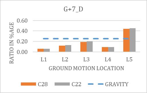
Below is the list of observations are drawn from lineartimehistorystudiesbyusingETABSmodels:
•Wediscoveredthatverticalearthquakegroundmovements hadaconsiderableinfluenceontheresponseoveraflatslab building.
• It is worth noting that the majority of the maximum outputs in the form of axial force in column, deflection of slabs, and punching shear at slab column junctions are almostidenticaltothePeekGroundAccelerationinspecific appliedgroundmovements.
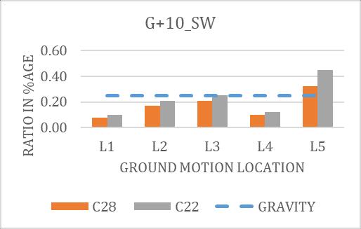
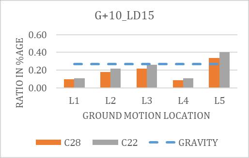
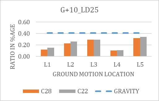
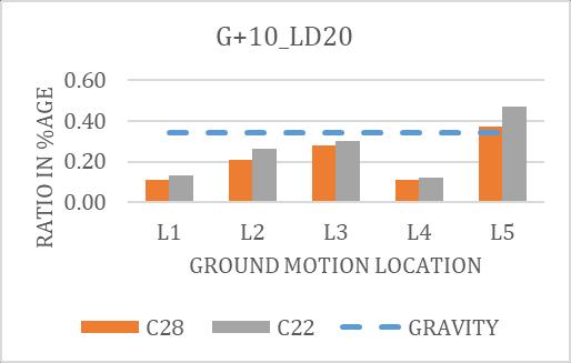
• We discovered a maximum of 85.1% of axial force in columnowingtoverticalmotionwhencomparedtogravity loads,whichissufficienttocausecolumnfailurebysplitting whenconsideredascombination.
• It's also worth noting that the influence of vertical earthquakeforcesonaxialloadsincolumnsrisesininterior columns while decreasing equally in outer perimeter columns
•Wediscoveredamaxriseof146.3%indeflectionofslab duetoverticalaccelerationascomparedtogravityloads.

• Slab deflections caused only by vertical motions do not exceedthepermittedlimitsetbyIS456-2000,butin60%of cases,theysurpass50%ofthelimit.
•Wealsoshowthatintroducingashearwalldoesnotreduce verticaldeflectionordisplacementasmuchasitdoeslateral displacement.eventhoughweonlyinstalledshearwallsat allcorners,theirefficiencyagainstverticalmotionshouldbe testedbyprovidingatotherareastoo.
• It is noticed that the most damaging effects of vertical motionareonpunchingshearatthejunctionofcolumn& flat slab, and this varies depending on thickness of slab & droppedpanels.
International Research Journal of Engineering and Technology (IRJET) e-ISSN: 2395-0056

Volume: 10 Issue: 06 | Jun 2023
•Onlyverticalearthquakeforceresultedinamaximumof 0.52punchingshearratio.Maximumof208%ofpunching stress is raised in percentage terms, which is sufficient to causegradualcollapseofanyflatplatebuilding.
•Punchingshearstressescausedbyverticalmotionsurpass punchingshearstressescausedbygravityloadsin40%of therecords.
• In a flat slab building, lateral earthquake force is often totally controlled by shear wall or partly controlled by specialmomentresistingframewhileinteriorcolumnsare intended to behave as gravity columns, although this is hazardousunderverticalearthquakemotion.
IwouldliketooffermyheartfeltgratitudetoProf.Aakash Rajeshkumar Sutharhis invaluable advice and encouragementinmyresearchwork.
[1] Elnashai, A., & Papazoglou, A. (1997). Procedure and spectraforanalysisofRCstructuressubjectedtostrong vertical earthquake loads. Journal of Earthquake Engineering - J EARTHQUAKE ENG, 1, 121–155. Doi:10.1080/13632469708962364
[2] Kayastha, N. B., & Debbarma, R. (2019). Seismic performance of reinforced concrete building with flat slab. Proceedings of the international conference on sustainable materials and structures for civil infrastructures (smsci2019). Https://doi.org/10.1063/1.5127127
[3] Shrestha,Bipin.(2009).Verticalgroundmotionsandits effect on engineering structures: a state-of-the-art review.10.13140/2.1.2863.6165.
[4] Siyun Kim, Sung Jig Kim, Chunho Chang, "Analytical AssessmentoftheEffectofVerticalGroundMotionon RC Frames Designed for Gravity Loads with Various Geometric Configurations", Advances in Civil Engineering, vol. 2018, Article ID 4029142, 11 pages, 2018.https://doi.org/10.1155/2018/4029142
[5] Di Sarno, L., Elnashai, A., & Manfredi, G. (2011, May). AssessmentofRCcolumnssubjectedtohorizontaland vertical ground motions recorded during the 2009 L’Aquila (Italy) earthquake. Engineering Structures, 33(5), 1514–1535. Https://doi.org/10.1016/j.engstruct.2011.01.023
[6] Collier, C. J., & Elnashai, A. S. (2001). A procedure for combiningverticalandhorizontalseismicactioneffects. Journal of Earthquake Engineering, 5(4), 521–539. Doi:10.1080/13632460109350404
[7] Biradar, P., Kulkarni, K., & Jamble, N. (2016, July 1). SeismicPerformanceofHighRiseFlatSlabBuildingwith Various Lateral Load Resisting Systems. Seismic Performance of High Rise Flat Slab Building With Various Lateral Load Resisting Systems. Http://www.journal.bonfring.org/abstract.php?Id=4&ar chiveid=533
[8] Mohana,H.S.,&Kavan,M.R.(2015).ComparativeStudy of Flat Slab and Conventional Slab Structure Using ETABS for Different Earthquake Zones of India. International Research Journal of Engineering and Technology,2(03),1931-1936.
[9] https://www.strongmotioncenter.org/vdc/scripts/eart hquakes.plx
[10] https://ngawest2.berkeley.edu/users/sign_in