Design, Analysis and Comparative Study of Exhaust Manifold for a Multi-Cylinder Four Stroke SI Engine using CFD
Vivek Chaudhary1, Dr G. Amba Prasad Rao21Post Graduate Student, Dept. of Mechanical Engineering, NIT Warangal

2Professor, Dept. of Mechanical Engineering, NIT Warangal, Telangana, India ***
Abstract - Gas exchange phenomena of an IC Engine take place through intake and exhaust manifolds. The engine’s performance is influenced by the gas exchange process. The engine's performance improves when the exhaust manifold is in good condition. In the present work, an attempt is made to the modify exhaust manifold by upgrading its design for improved performance for a chosen multi-cylinder engine configuration. The primary objective of the present work is to enhance the design to reduce backpressure in the exhaust manifold for enhanced engine performance. Computational fluid dynamics (CFD) is a popular and current operating software that is widely used. CFD is largely used in the automobile industry to lower the cost of designing and analyzing various models in the fluid flow area. The flow through the exhaust manifold is performed using commercially available software. Efforts are made through CFD software to analyze various shapes of exhaust manifolds. Five distinct models were built and thoroughly analyzedusing velocity and pressure contours to get the optimum shape for minimal backpressure and high exhaust velocity. The velocity contour and pressure contour are used to comparesix distinct models, and the best potential modelforlowbackpressureand high exhaust velocity is given. Among the six models designed, model 6 yielded satisfactory performance
Key Words: Multi-CylinderEngine,ExhaustManifold,Back Pressure,ExhaustVelocity,ExhaustTemperature
1.INTRODUCTION
OneofthemostsignificantcomponentsofanICengineisthe exhaustmanifold.Exhaustmanifolddesignisachallenging techniquebecauseitisdependentonmanyparameterssuch asexhaustvelocity,backpressure,mechanicalefficiency,and soon.Theimportanceofanyofthesecriteriaisdetermined bythedesigner'srequirements.Backpressure,exitexhaust velocity, and power required are some of the exhaust manifold design considerations. The exhaust manifold is constructedof castironor stainless steel.It collectsgases from several cylinders and routes them to the exhaust manifold.Manystudiesandresearchhavebeenconductedin this topic. The study's goal is to gain a thorough understanding of the manifold operation, flow property distribution,andheattransferdetails.Duetotheinclusionof
somanycomponents,itisimpossibletoreplicatetheactual scenarioinamodel.Theoutputgasesfrommorethantwo cylinders are collected into a single pipe in an exhaust manifold of any multicylinder engine. The outlet of the multicylinder heads is connected to the inlet of the multicylinderexhaustmanifold.Inmulticylinderengines,the exhaust manifold is attached to the engine and is the principalportionwherethestreamfrommultiplecylinders is to be collected into a single pipe. The accumulated hot exhaustgasesexitthroughthesingleexhaustmanifoldoutlet fromthecylinderheader.Fortheenginetoworkoptimally, the backpressure of the exhaust manifold at the output shouldbereduced.Fordomesticautomobiles,thehigherthe backpressure, the poorer the performance or economy. Higherbackpressureisrequiredforracecarstoreachhigher speeds in less time. To achieve optimal mechanical and thermal efficiency, the exhaust gases should have a high velocityattheexhaustmanifold'sexit.
Backpressureisatypicalissueconnectedwiththeexhaust manifold.Accordingtotheliteratureresearch,muchwork hasbeendonetoimprovetheexhaustmanifoldinorderto improvetheengine'sperformance.TheCFDapproachsaves manufacturing costs and production time. According to a surveyoftheliterature,manyexhaustmanifoldstudieshave beenconductedutilizingtheCFDtechnique.Thefollowing aresomeexcerptsfromtheliteraturereview.
Dr.M.SenthilKumar,Dr.S.Sendilvelan,PL.S.Muthaiah[1] have examined the exhaust manifold in order to reduce backpressureintheexhaustmanifoldandimproveexhaust gas filtration. Modification of the geometry of exhaust manifoldwasdonebyshiftingthesizeoftheconicalregion oftheexhaustmanifoldaswellasthegridsizeofthemeshed wirepackedthroughthe exhaustmanifold.Whenthegrid size is increased, the filtration level lowers; when the filtration level decreases, the exhaust system emits more exhaust. When the grid size decreases, backpressure is formedintheexhaustmanifold,causingengineefficiencyto decline. CFD is used to evaluate the exhaust manifold and select the best-design model with the least amount of backpressureandthemostamountofPMfiltration.
SiddaveerSangamad,VivekanandNavadagi[2]usedCFDto studytheflowthroughtwodistinctversionsofanexhaust manifold. They analyzed two models: one with the base geometryoftheexhaustmanifoldandonewiththemodified geometry of the exhaust manifold. Both models were analyzedutilizingpressureandvelocitycontours.Themajor goal of this work is to enhance the exit velocity when the exhaust manifold has a low back pressure, which boosts volumetricefficiencyandengineefficiency.Theyconcluded that the present model is modified by modifying its geometrywhilemaintainingthesameboundaryconstraints. The new model's results outperform the current model becausetheyanalyzedvelocityandpressurecontourstofind the lowest back pressure while boosting the volumetric efficiencyoftheengine.
KSUmesh,VKPravin,KRajagopal [3]performedboth the CFDstudyandexperimentalverificationoftheinfluenceof exhaustmanifoldgeometry.Theydesignedandanalyzedtwo differentmodels,anexistingmodelandamodifiedmodel. They changed the geometry of the existing model of an exhaust manifold, which was then analyzed using parameterssuchasvelocitycontoursandpressurecontours, and both models were constructed and tested. In CFD analysis,theredesignedmodelyieldedthebestresults,with little backpressure in the exhaust manifold and increased volumetricefficiencyoftheengine.Thesameresultswere achievedafterconductingtheexperimentswithbothmodels. Itiseasytodeducethattheexperimentalresultsmatchthe CFDanalyticalresults.Experimentalanalysisvalidatedthe CFDanalysisresults.
MohdsajidAhmed,KailashBA,GowreeshSS[4]constructed five alternative exhaust manifold models and analyzed in thispaper.Theprimarytaskistoenhancethedesignofan exhaust manifold since minimizing backpressure in the exhaust manifold improves engine efficiency and performance.Theyanalyzedthesimpleflowofanexhaust using velocity and pressure contours for five distinct developedmodels,comparedthefivemodelsusingpressure andvelocitycontours,andthenchosethebestonemodel. They found that model number five is the best model becauseithasthelowestbackpressureandsmoothflowof an exhaust without recirculation. It also has the lowest turbulent kinetic energy and the highest output velocity when compared to other models. Using this exhaust manifold,higherexhaustvelocityandlowerbackpressure canbeachieved.
2. METHODOLOGY

2.1 CAD Modelling of Exhaust Manifold
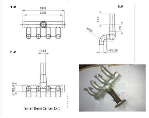
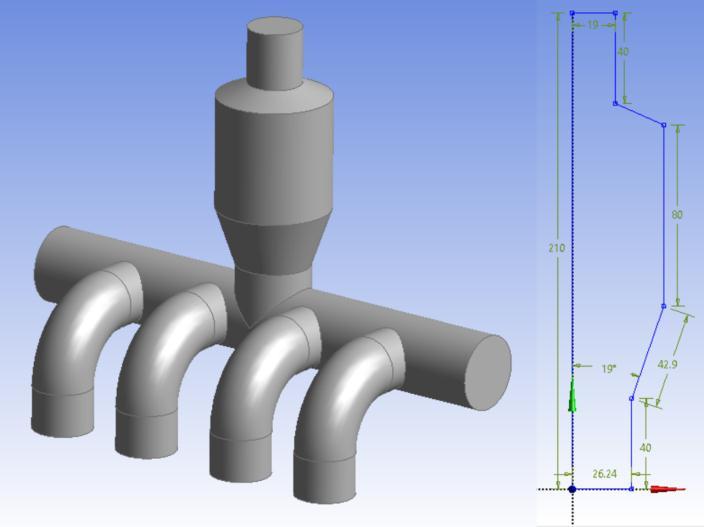
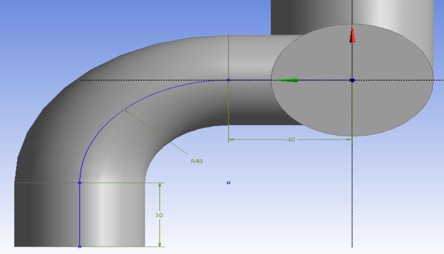
Thecomputeraideddrawingsoftwarenameddesignmodeler isusedtocreatethefivemodels.AcommercialCFDtoolis used to analyze six different models. Meshing software is used to name boundaries and discretize the models. Dimensions in mm are provided for the basic CAD models thatwereused.
Model
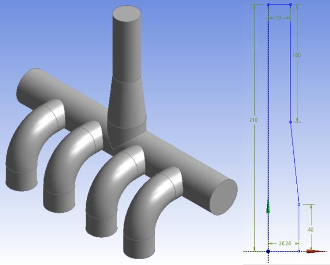
Inthemodel1shapeoftheinlethasbeenmodifiedfrom straightinlettoconvergentinletand3Dmodelandits2Dsketchisshown.
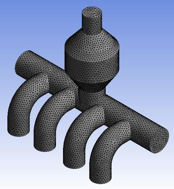
Inmodel3thedivergencelengthoftheoutletisincreased andconvergencelengthisdecreased.
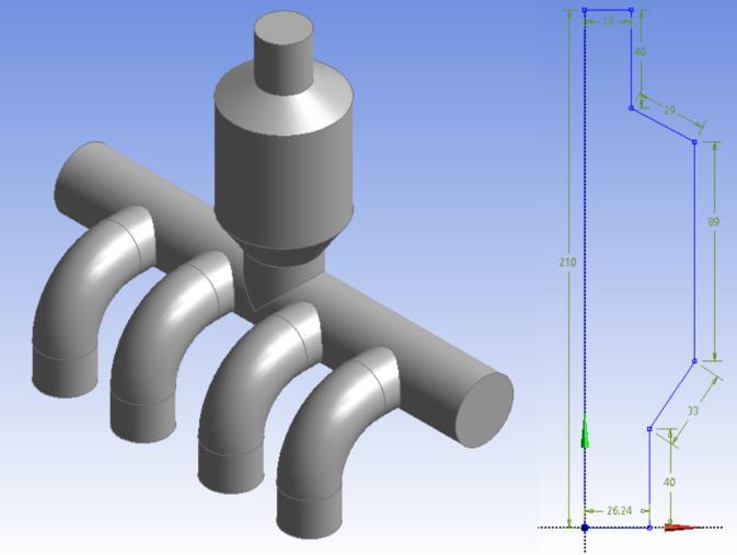
Inmodel4thedivergencelengthoftheoutletisdecreased andtheconvergencelengthisincreased.

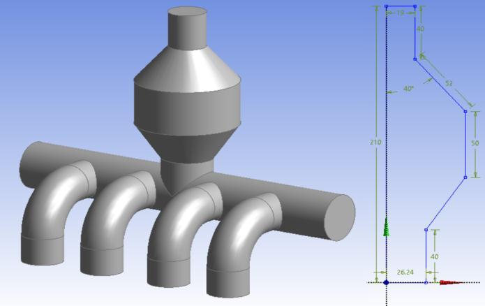
Inmodel5thedivergentareaandconvergentareaof theoutletarekeptequalandstraightareaisdecreased.
2.3 Boundary Conditions
Table -2: BoundaryConditions
Named Selection Boundary Type Boundary Condition
Inlet Patch Massflowrateinlet
Outlet Patch Pressureoutlet
Walls Wall NoSlipandConvection
Thefluidconsideredisairanddefaultmaterialpropertiesfor air have been imported from Fluent library. The flow was assumed to be steady state, turbulent along with heat transferphenomenon.Theboundaryconditionsusedatinlet andoutletboundariesaremassflowrateinletandpressure outletboundaryconditions Airtemperatureatinletisused as313 oC Noslipboundaryconditionwasusedonthewalls alongwithconvectionvalueof10W/m2Kforheatdissipation throughwallstoatmosphere.
Inlet1=0.00188kg/s,Inlet2=0.00188kg/s,Inlet3=0.00188 kg/s,Inlet4=0.00188kg/s,Outlet=0Pa.

2.4 Meshing Details
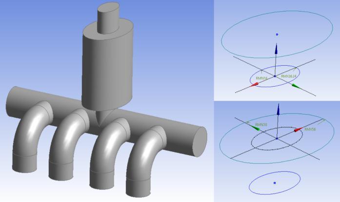
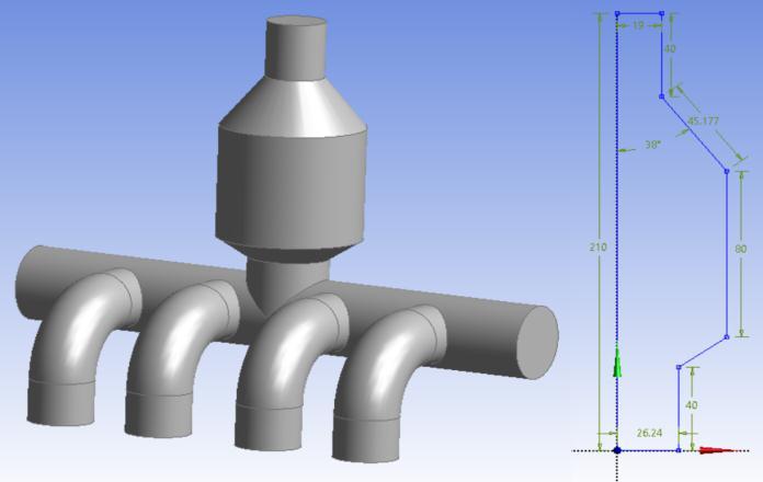
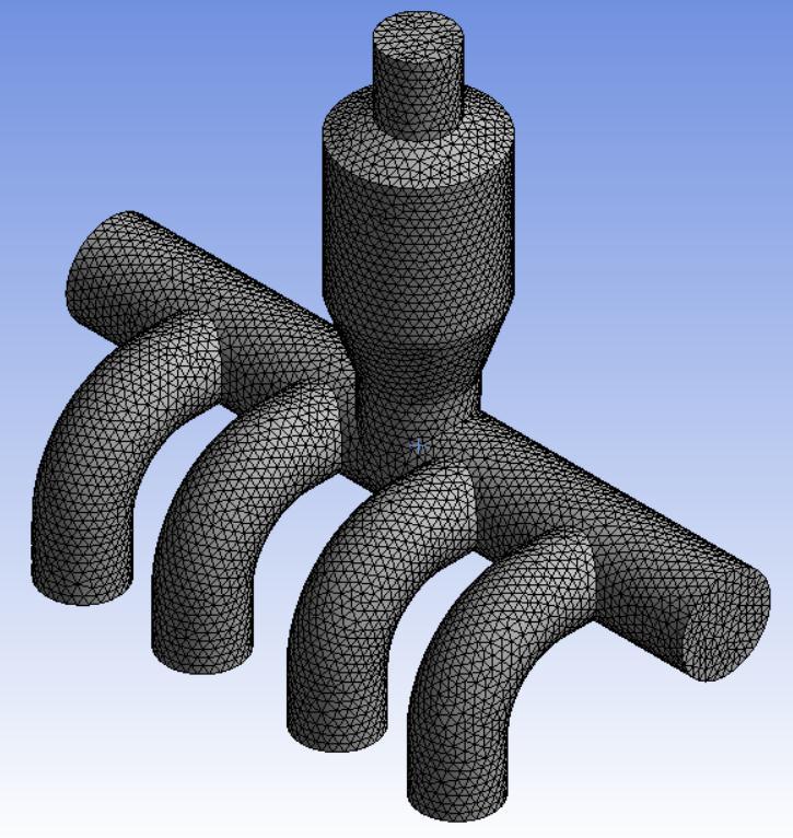
Inmodel6thetheellipticalcross-sectionhasbeenusedwith sharpexpansionandconvergenceshapetowardsoutlet.
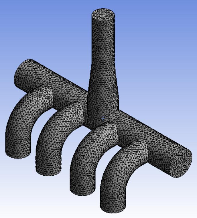
Totalnumberofnodes-23052
Totalnumberofnodes-113977
MaximumSkewness-0.67
AverageSkewness-0.222
Totalnumberofnodes-29329
Totalnumberofnodes-148220
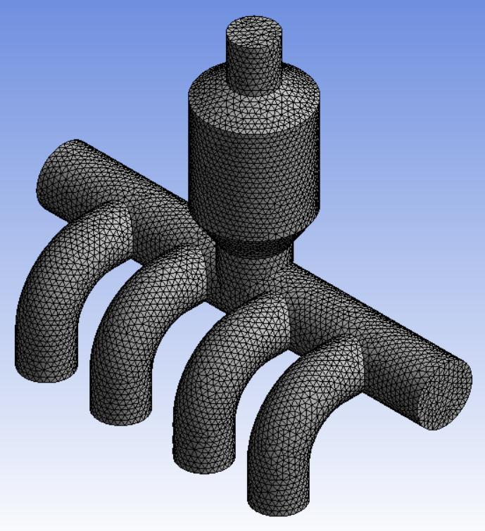
MaximumSkewness-0.698
AverageSkewness-0.221
Totalnumberofnodes-29650
Totalnumberofnodes-150082
MaximumSkewness-0.698
AverageSkewness-0.219
Totalnumberofnodes-27608
Totalnumberofnodes-138885

MaximumSkewness-0.697
AverageSkewness-0.222
Totalnumberofnodes-30317
Totalnumberofnodes-153864
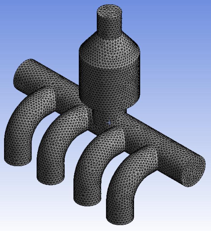
MaximumSkewness-0.7
AverageSkewness-0.22
Totalnumberofnodes-30751
Totalnumberofnodes-156290
MaximumSkewness-0.669
AverageSkewness-0.221
3. RESULTS AND DISCUSSION
3.1 Model 1 Results
Fig. 14 gives the variation of pressure in the exhaust manifoldformodel1.Itisseenthatpressureatoutletis0Pa as specified in the boundary condition. However, backpressure is generated and can be seen increasing graduallyfromoutlettowardsinlet.
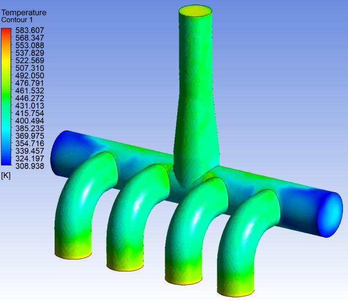
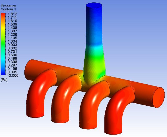
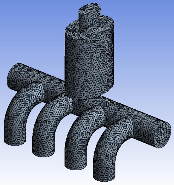
Fig. 15 gives the variation of temperature in the exhaust manifoldformodel1. Itcanbeseenthathotairiscoming thoughall4inletsatsametemperatureandastheairpasses throughthemanifolditlosesheattotheenvironmentdueto convection boundary condition through walls. Relatively coolertemperatureregionsareformedatthesideextended region of exhaust manifold as hot air tries to flow out through the outlet directly without flowing to the side extendedregions.
From the fig. 16 it is evident that due to the convergent shape of the inlet, velocities are found to be lower at the connectingarea and inlet. Thelowvelocityresultsin high
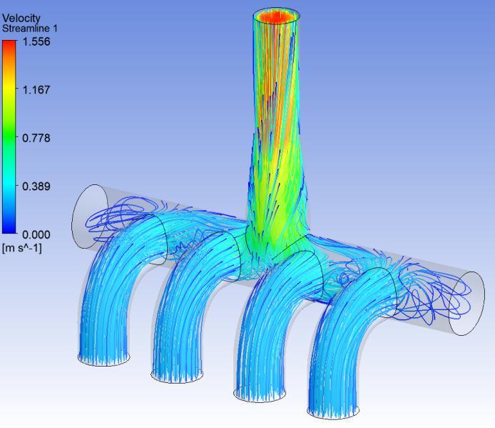

backpressure. It is observed that exhaust velocities considerablydecreasebydesigningthemanifoldusingthe convergentinlet.Itisobservedthataircirculatesintheside extendedregionsoftheexhaustmanifold.
Fig. 18 gives the variation of temperature in the exhaust manifold for model 2. Same cold region phenomenon like model1ontheextendedsideregionisobservedformodel2. It can also be seen that cold temperature spot is getting formedonthedivergentportionoftheexhaustoutlet.This occursduetosuddenexpansionofairflowcrosssection
Figure17givesthepressuredistributionoverentiredomain formodel2.Pressureishigherattheoutletincomparison withmodel 1. Itis evident thatthepressure is highatthe inlets of model 2. Pressure is high at the middle of the exhaustmanifoldincomparisonwiththeexitoftheoutlet.

Figure 19 shows velocity distribution inside exhaust manifold.Itisobservedthatthevelocityattheinletsisless anditincreasesattheoutlet.Itisseenthatthevelocitiesare foundtobeslightlyhigherattheoutletincomparisonswith model 1. It is observed that the exhaust velocities are considerablyincreasingbydesigningtheexhaustmanifold usingthisoutletincomparisonwithmodel1.
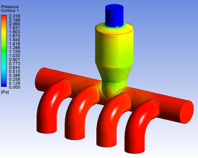
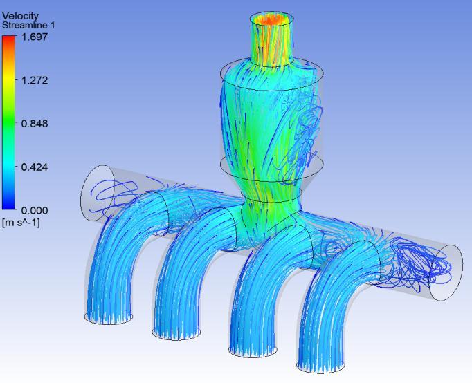
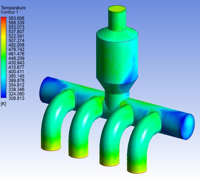
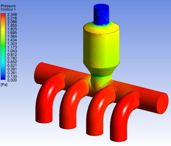
Figure20givesthepressuredistributionformodel3.Itis found that the pressure is higher at the inlets. Pressure is higher at the inlet in comparison with the model 1 and almostsameincomparisontomodel 2.Itisobservedthat exhaustpressureisalmostsamebydesigningthemanifold by decreasing the convergent length of the outlet even furthercomparedtomodel2
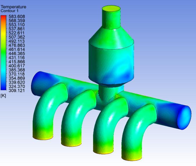
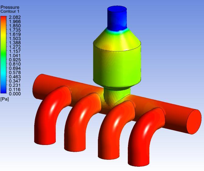
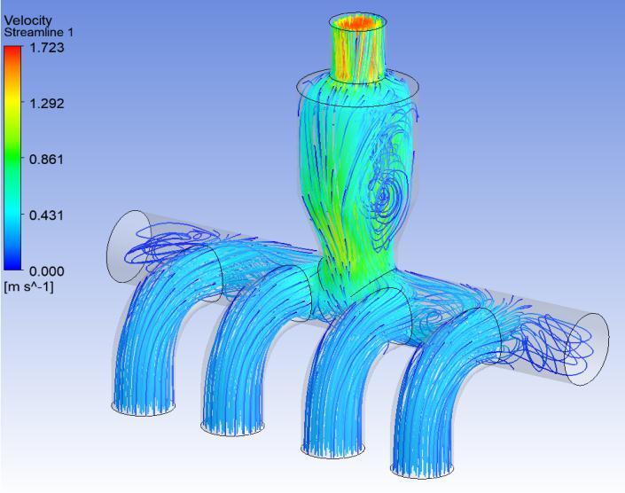
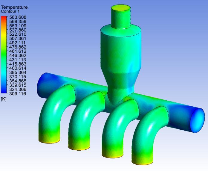
Figure22givesthevelocitycontourofthemodel3.Itisseen thatthevelocityishigherattheoutletincomparisonwith the model 1 and 2. It is observed that exhaust velocities considerablyincreasebydesigningthemanifoldusingthe divergent-convergentoutlet.Itisobservedthatthevelocity ishigherattheoutlet.
3.4 Model 4 Results
Fig. 21 gives the variation of temperature in the exhaust manifoldformodel3 Coldregionphenomenonlikemodel1 and 2 is observed on the extended side region of exhaust manifold.Itcanalsobeseenthatcoldtemperaturespotis gettingformedonthedivergentportionoftheexhaustoutlet likemodel2.Thisagainoccursduetosuddenexpansionof airflowcrosssectionarea.
Figure23givesthepressuredistributionformodel4.Itis found that the pressure is lower in comparison with the model 2 and 3 but slightly higher than model 1. Higher pressuresareobservedattheinlets.Itisobservedthatby reducing the divergent length of the outlet the pressure decreasescomparedtomodel2and3.

Fig. 24 gives the variation of temperature in the exhaust manifoldformodel4.Coldregionphenomenonlikemodel1, 2and3isobservedontheextendedsideregionofexhaust manifold.Itcanalsobeseenthatcoldtemperaturespotis gettingformedonthedivergentportionoftheexhaustoutlet likemodel2and3.Thisphenomenonoccursduetosudden expansionofairflowcrosssectionarea.
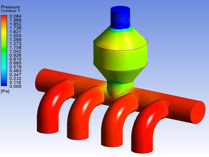
Figure26givesthepressuredistributionformodel5.Itis found that the pressure is higher in comparison with the model 1 but it is lower compared to model 2 and 3. Back pressureisslightlyhigherthanmodel4.Higherpressureis observed at the inlets. It is observed that by reducing the straight length of the outlet the pressure increases considerably.

Figure 25 gives the velocity contour of model 4. It is observed that due to the sudden expansion of the area of outletvelocitiesarefoundtoslightlyincreasecomparedto model 1 at the outlet. It is observed that the exhaust velocities are slightly increasing by designing the exhaust manifold by reducing the divergent length of the outlet in comparisonwithmodel1.Velocitiesarefoundtobehigher attheoutletduetoconvergentcrosssectionareanearoutlet oftheexhaustmanifold.
3.5
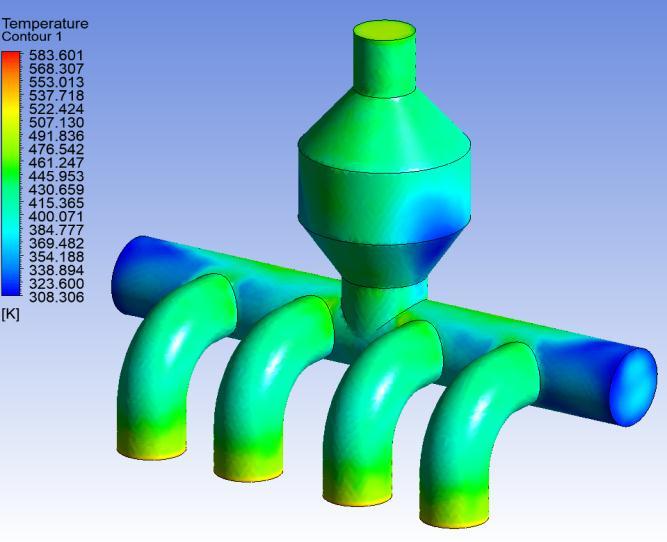
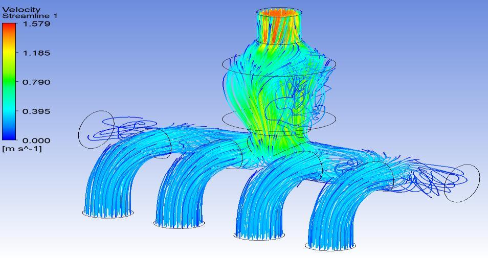
Fig. 27 gives the variation of temperature in the exhaust manifold for model 5. Cold region phenomenon is again occurring like model 1, 2, 3 and 4 and is observed on the extendedsideregionofexhaustmanifold.Itcanalsobeseen that cold temperature spot is getting formed on the divergentportionandstraightportionoftheexhaustoutlet like model 2, 3 and 4. This phenomenon occurs due to sudden expansion of air flow cross section area after the connectingregion
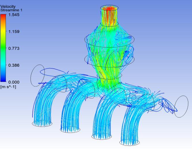
Figure 28 gives the velocity distribution in model 5. It is observedthatduetothedivergentconvergentshapeofthe outlet,velocityisalmostsimilarattheoutletincomparison with model 1. It is observed that the exhaust velocities remainalmostsamebydesigningtheexhaustmanifoldby reducingthestraightlengthoftheoutletincomparisonwith model1 Thevelocitystreamlinesofthemodel5showthat the flow is uniform in comparison with the other models. Verylessrecirculationisobservedinthemodelcomparedto allothermodels
3.6 Model 6 Results
Figure29givesthepressuredistributionformodel 6.Itis foundthatthebackpressureishigherincomparisonwith themodel1,2,3,4and5 Higherpressureisobservedatthe inlet region. It is observed that by increasing the straight lengthoftheoutletthepressureincreasesconsiderably.
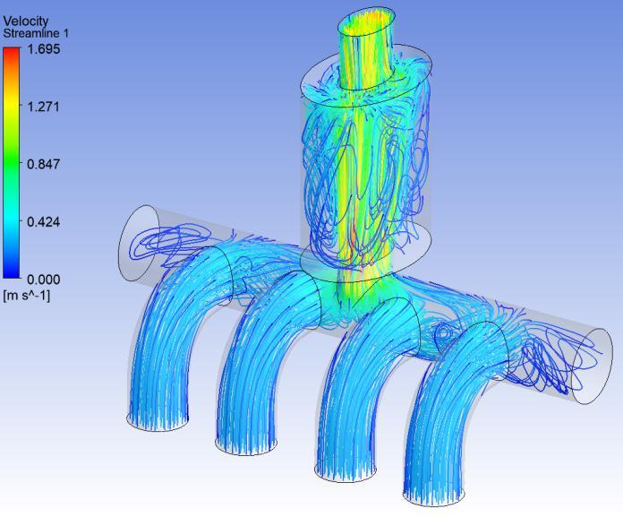
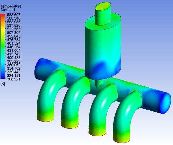
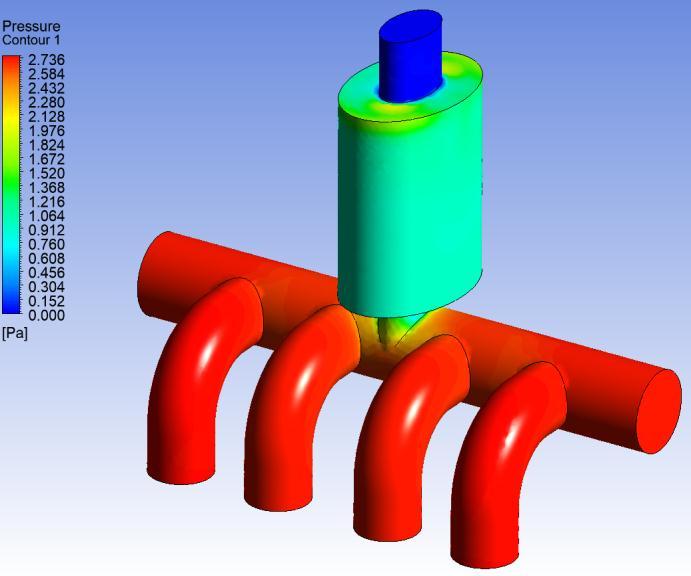

Fig. 30 gives the variation of temperature in the exhaust manifold for model 6 Cold region phenomenon is again occurring like model 1, 2, 3, 4, 5 and is observed on the extendedsideregionofexhaustmanifold.Itcanalsobeseen that cold temperature spot is getting formed on the divergentportionandstraightportionoftheexhaustoutlet This cold region is bigger and forming over entire circumferenceoftheoutletneartheconnectingregion.This phenomenonoccursduetosharpexpansionofairflowcross sectionareaaftertheconnectingregion.
VelocityStreamlines
Figure 31 gives the velocity distribution in model 6. It is observedthatduetothesharpdivergentconvergentshape of the outlet, velocity is lower at the outlet in comparison
withmodel1,2,3,4and5.Itisobservedthattheexhaust velocity decreases by designing the exhaust manifold by increasing the straight length of the outlet in comparison withmodel5 Thevelocitystreamlinesofthemodel5show thattheflowisrecirculatinginthesideextendedregionsas wellasthesharpdivergentoutletregion
Comparisonofalltheresultsfrommodel1,2,3,4,5and6 havebeenlisteddowninthetablebelow.
Table -3: Resultscomparisonforallmodels
convergentdivergentshapeandlongerstraightlength butitalsoreducestheoutlettemperature.
Thenextbestdesignwouldbemodel5withslightly higher back pressure and slightly higher velocity comparedtomodel1alongwithoutlettemperature valueof210.6oC.Temperaturereductionof4.11%at outletisobservedwiththisdesignincomparisonto model1.
ACKNOWLEDGEMENT
TheauthorsaregratefultotheauthoritiesofNITWarangal forprovidingallfacilities.
REFERENCES
[1] PL.S.Muthaiah,Dr.M.Senthilkumar,Dr.S.Sendilvelan, “CFDanalysisofcatalyticconvertertoreduceparticulate matter and achieve limited back pressure in Diesel engine”,volume:10Issue:5Oct-2010
[2] Vivekanand Navadagi, Siddaveer Sangamad. “CFD analysis of exhaust manifold of multi-cylinder petrol engineforoptimalgeometrytoreducebackpressure”, volume:3Issue:3March-2014
4. CONCLUSIONS
Differentexhaustmanifoldsareanalyzedinthisworkusing commercialCAEsoftware,andtheflowofexhaustisseen,as wellasthevelocity,pressureandtemperaturedistribution throughoutthelengthoftheexhaustmanifoldisdetermined throughsimulation.CFDPostprocessingwasusedtoanalyze theoutcomesofsixdifferentmodels.Theusageofvarious shapesofexhaustmanifoldsaidsintheeasyflowofexhaust aswellasreductioninexhaustoutlettemperature.
Model 6 facilitates low velocity flow of exhaust and highbackpressureattheexhaustoutletbuttheoutlet temperature is lowest in comparison with all other models.
Velocityattheoutletofmodel6islesscomparedtoall othermodelsandhencethebackpressureincreases considerably.
The optimum design for an exhaust manifold to achieve lowest outlet temperature is Model 6 with 2.74 Pa back pressure, outlet velocity 1.17m/s and outlet temperature of 206.58oC. Temperature reduction of 5.94% at outlet is observed with this designincomparisontomodel1.
Largerbackpressureandlowerexhaustvelocitiesare achieved by using exhaust manifolds with sharp
[3] KS Umesh, VK Pravin, K Rajagopal, “CFD analysis of exhaust manifold of multi-cylinder SI engine to determine optimal geometry for reducing emission”, volume:3Issue:4Oct-2013
[4] MohdSajidAhmed,KailashBA,Gowreesh,“Designand analysisofamulti-cylinderfourstrokeSIengineexhaust manifoldusingCFDtechnique”,volume:02Issue:09Dec2015
[5] P. Seenikannan, V. M. Periasamy and P. Nagaraj, “ A designstrategyforvolumetricefficiencyimprovement inamulti-cylinderstationarydieselengineitsvalidity undertransientoperation”,volume:5issue:3,2008.
[6] Kimetal,“Anon-noblemetalbasedcatalyticconverter fortwostrokes,two-wheelerapplications”,SAEPaper No.2001011303,2001.
[7] C. Lahousse, B. Kern, H. Hadrane and L. Faillon MulticylinderSIEngine”InternationalJournalofEngineering & Science Research IJESR/July 2013/ Vol-3/Issue7/342-353.
[8] Binachietal,“Possibilitiesoftheapplicationofcatalyst technologiesforthecontrolofparticulateemissionfor diesel vehicles”, SAE Transaction 2001, paper no. 2001280044.

