A Design Strategy Based On Optimization Techniques For Compressor Support Bracket And Vibration Analysis By Using FFT
Pareshkumar Nawanathsing Rajput1 , Amol B. Gaikwad2 , Kharad B.N.31Sholar,Dept of Mechanical Engg, Vishwabharti Academy’s College of Engineering, Ahmednagar, Maharashtra, India
2Asst. Prof. Dept of Mechanical Engg, Dr. D.Y.Patil School of Engineering, Pune, Maharashtra, India

3Asst. Prof. Dept of Mechanical Engg, Vishwabharti Academy’s College of Engineering, Ahmednagar, Maharashtra, India
***
Abstract:
Theobjectiveofthisprojectistoanalyzeandoptimizethe bracket'sweightbyselectingadifferentmaterial.
Reducingtheweightofthebracketnotonlyhelpsdecrease raw material costs but also improves overall efficiency, althoughtheimpactmaybeminimal.Thisstudyalsoaimsto identify the factors that contribute to bracket failure and assesstheeffectsofoptimizationthroughvariousanalyses, includingvibrationanalysis,deformationanalysis,andVon Misesstressanalysis.
TheprojectinvolvesthedesignofanACmountingbracket, which is created using modeling software and analyzed using ANSYS Software. The design of experiments (DOE) technique is employed to develop a glass fiber reinforced plastic(GFRP)bracket.TheGFRPbracketisthensubjected toanalysisusingANSYStoevaluateitsperformance.
Theprojectreportsaweightreductionof66.67%achieved intheredesigned bracket.Additionally,thefrequenciesof the steel and composite brackets are to be checked. This refers to assessing the natural frequencies or resonant frequencies of the brackets to ensure they fall within acceptableranges.Itiscrucialtoavoidresonancesthatcould leadtoexcessivevibrationorfailure.
TheprojectsuggeststhattheGFRPbracketoffersadvantages over thesteel bracket in termsofvibration.Thevibration levelsof the GFRPmaterial aremeasured by connecting a probetomonitoraccelerationanddisplacementinrelation to the motor's RPM. Furthermore, the weight reduction achievedthroughtheGFRPcompressormountingbracket leadstoreducednoisecomparedtothesteelbracket.
Keywords: - Compressor mounting bracket, ANSYS, Design of Experiments
1.INTRODUCTION:
The compressor is a crucial component in the automotive air conditioning system and is subjected to unbalancedforcesgeneratedbytheengineandcompressor itself, resulting in structural vibrations. To mitigate these
vibratory forces, a compressor mounting bracket is employedtosupportthecompressor.
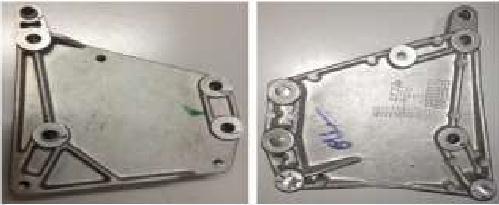
Optimization is a fundamental aspect of problem-solving in a range of disciplines, including engineeringandeconomics.Theprocessofdecision-making involves making choices among different options, and the goalistomaketheoptimaldecision.Theevaluationofthese alternativesistypicallydeterminedbyanobjectivefunction or performance index, which measures their quality. Optimization theory and methods are concerned with identifyingthebestpossiblealternativebasedonthegiven objectivefunction.
1.1 Composite Material
1.1.1 Polymer Matrix Composite
Resinslikeepoxiesandpolyestersalonedonotpossesshigh mechanical properties, limiting their use in structural manufacturing. However, when combined with reinforcementintheformoffibers,theresultingcomposite exhibits enhanced tensile and compressive properties compared to the solid resin. These properties may not be immediatelyevidentintheindividualcomponents.
Fibers in the composite primarily contribute to tensile strengthalongtheirlength.Whenthefibersareintegrated with the resin, the load applied to the composite is distributedacrosstheresin,effectivelyspreadingtheload amongtheindividualfibers.Thecombinationofresinand
reinforcing fiber in a polymer matrix composite yields exceptionalproperties,improvingtheoverallperformance ofthematerial.
The properties of the composite are influenced by several factors:
Individualpropertiesofthefiberandresin:Themechanical properties of the composite depend on the inherent characteristicsofthefibersandtheresinused.
Mixtureratiooffiberandresin:Theproportionoffibersto resininthecompositeaffectsitsoverallproperties.Varying the ratio can lead to different levels of reinforcement and mechanicalperformance.
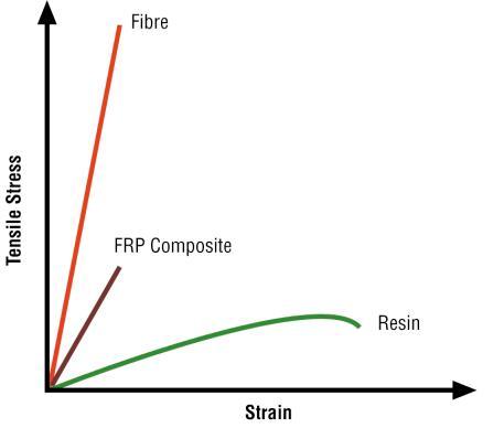

Geometry and fiber orientation: The arrangement and orientation of the fibers within the composite play a significant role in determining its mechanical behavior. Factors such as fiber alignment and stacking sequence impacttheoverallstrengthandstiffnessofthecomposite. Byconsideringthesefactors,thepropertiesofthecomposite canbetailoredtomeetspecificrequirements,resultingina materialthatcombinesthedesirablecharacteristicsofboth theresinmatrixandthereinforcingfiber.
Designing the compressor mounting bracket for automotive air conditioning applications using conventionalmaterials.
Designingthecompressormountingbracketusing GFRP(GlassFiberReinforcedPlastic)materialand conducting various experimental analyses on the compositematerial.
Performingvibrationandnoiseanalysis,aswellas optimization using Finite Element Analysis (FEA) techniquesontheexistingmaterialdesign.
Comparing and selecting the most suitable alternative based on the results obtained from stressanalysis.
Manufacturingandtestingthechosenalternative, and comparing the experimental results with the FEAandtheoreticalanalyses.
3. ANALYTICAL CALCULATIONS OF COMPRESSOR MOUNTING BRACKET
Bracket’swidth,whichcanbeeithernarrowerorwiderthan the compressor's width. This configuration results in the brackethavingaclosedLshape,withdimensionsof446mm inlengthand150mminwidth.
The following stresses need to be evaluated:
Shearstress.
Directandbendingstress.
A weight of 15 kg is applied precisely on the bracket. Thematerialselectedformanufacturingthebracketis steel.
Thecomponentinstalledontheautomobileexperiences forces acting independently in all three directions, equivalent to 3 times the acceleration due to gravity (3g).Theseforcesareappliedtothecompressor.
Thearea ofthe plateunderthecompressormeasures 450mmby150mm.
The existing design of the compressor mounting bracketmaynotbefullyoptimizedintermsofperformance, cost-effectiveness, and ease of manufacturing. There is a requirementtoenhancethedesignandoptimizethebracket toimproveitsoverallefficiency,reliability,andproduction feasibility.
2.1 Objectives Of The Project
The current work aims to achieve the following key objectives:
4. FINITE ELEMENT ANALYSIS

Various areas of interest commonly encountered in engineeringincludestructuralanalysis,heattransfer,fluid flow, mass transport, and electromagnetic potential. Addressing these problems typically involves solving boundaryvalueproblemsassociatedwithpartialdifferential equations. By formulating the problems using the finite elementmethod,asystemofalgebraicequationsisobtained asthesolution.
4.1
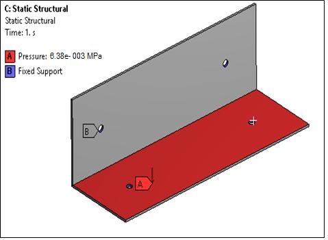
Fig.4.1:-Boundaryloadingconditionforsteelbracket. Figure4.1displaystheboundaryconditionsandloadingfor thestaticanalysis.Thefigureillustratestheapplicationofa totalpressureof0.006539MPaonthesurface,simulatinga 441 N load resulting from a 3 gram acceleration of the compressorassemblytowardsthebase.Additionally,fixed boundary conditions are applied to all four bolt holes to simulatetheboltedconnectionbetweenthebracketandthe chassis.Thebracketitselfhasamassofapproximately3.9 kg.
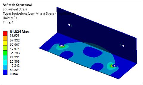
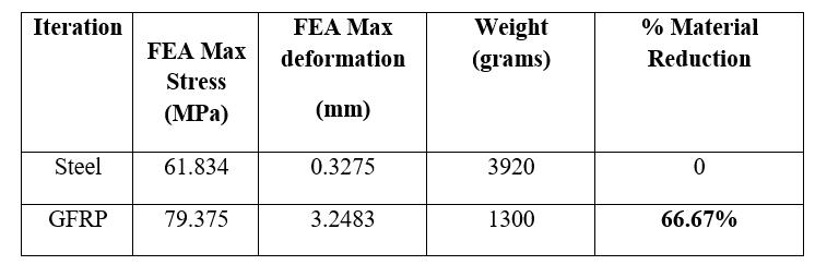
TheVonMisesstressplotrevealsthatthemaximumstress experiencedbythesteelbracketofthecompressor,resulting from the 3 gram loading, is 61.834 MPa. This value falls comfortably within the acceptance criterion of 185 MPa. Therefore,basedonthestaticFiniteElementAnalysis(FEA) results,itcanbeconcludedthatthesteeldesignisdeemed safe.
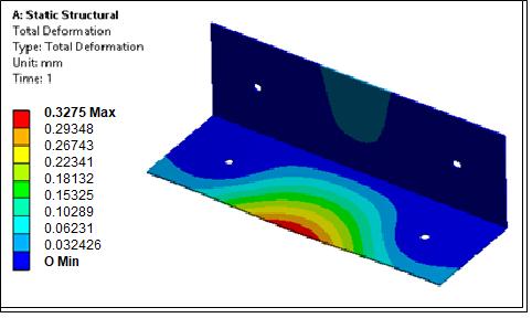
The total deformation of the steel bracket, as shown in Figure4.3,indicatesa maximumdeformationof0.33mm. Thisdeformationisconsiderednegligible,especiallywhen taking into account that only 1/3 of the actual load is continuouslyappliedtothebracketunderrealconditions.
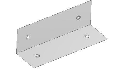
The surface of the model is extracted to generate the compressor support bracket using GFRP (Glass Fiber Reinforced Plastic) material. The bracket will be assigned appropriatemeshingsizeandthickness,consideringtheply material properties, within the Advance Composite PreprocessorofANSYS.
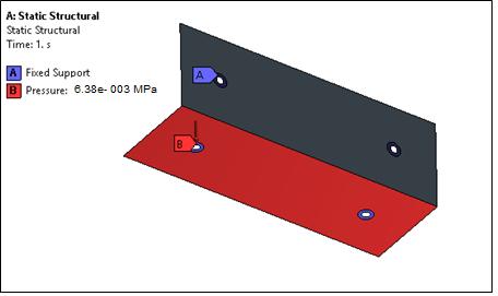
Figure 4.5 illustrates the boundary conditions appliedtothecompressionmountingbracket.Apressureof 0.006539MPaisappliedtothehorizontalface,simulatinga 441Nforceresultingfromthe3gramloadingoftheweight ofthecompressorassembly.
4.3
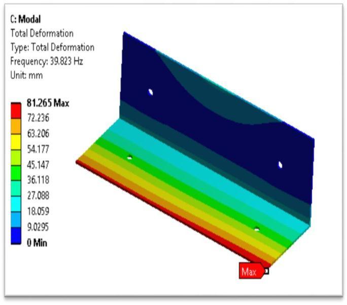
Modal analysis is conducted on both the steel and GFRP bracketstodeterminethelowest natural frequencyofthe bracketunderoperatingboundaryconditions.Thepurpose ofmodalanalysisistoensurethatthedesignmodifications made in the material do not adversely affect the system's firstorlowest natural frequency.Decreasesinthenatural frequencycanleadtodynamicresonanceinthecomponent, as low-frequency time-dependent loading may result in suddenprematurefailureofthebracket.

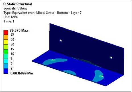
The maximum von Mises stress observed in the GFRPdesignis79.375MPa,representingapointstress.This stressvaluefallswithintheacceptancecriterionof100MPa usedinthedesign.
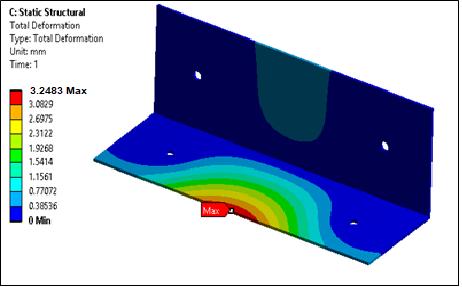
The maximum deformation plot for the GFRP design indicates a deformation of 3.2483 mm. This level of deformation is considered acceptable and falls within the permissiblelimitforthe3gramloadingcondition.
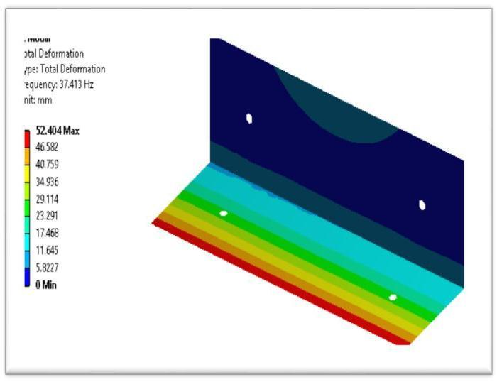
The mode shape plot illustrates the deformation patternassociatedwiththefirstnaturalfrequencyforboth the Steel and GFRP brackets. It is important to study the shape of deformation rather than focusing on the specific deformationvaluesdisplayedintheplot.Thedeformation valuesthemselvesdonotconveysignificantinformation,as theprimaryobjectiveistoanalyzeandunderstandthemode shapeforthefirstmodalfrequency.
5.2 Experimental Set up for Vibration Analysis using FFT Analyzer:
Once the natural frequency of the Compressor Mounting bracket is determined through Finite Element Analysis (FEA), it is further validated using an FFT (Fast Fourier Transform) analyzer. To simulate the actual mounting conditionsinthevehicle,thebracketismountedonafixture. The vertical side of the bracket is attached to the fixture, replicating the boundary conditions similar to those experiencedinthevehicle,whilethehorizontalsideisleft free.
5.3
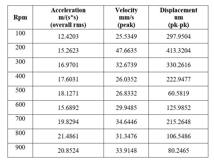
Table5.1.ResultforSteelBracket
5.
ForexperimentalvalidationGFRPmaterialbracketistobe manufacturedforthedesigndimensions.
5.1 Experimentation Procedure For Testing
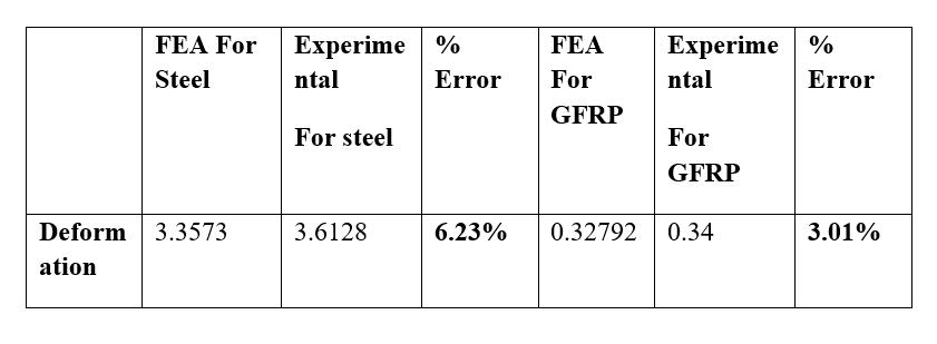
The experiments are performed using a Universal Testing Machine(UTM),whereaload-deformationtestisconducted underspecifiedloadingconditions,typicallywithaloadof 5000N.TheUTMprovidesresultsthatarecomparedwith theanalysisresultsobtainedfromFiniteElementAnalysis (FEA).
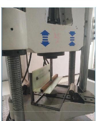

Figure 5.1 displays a photograph of the complete experimentalsetup,showcasingtheutilizationofacomputer tooperatetheUTMandrecordtheloadversusdisplacement data over time. It is worth noting that the UTM is fully automated.
Thus the rpm of motor increases acceleration and displacementgetchangei.esteelhasmoredisplacement.
5.4 Results for GFRP Bracket:-
Table5.2.ResultforGFRP
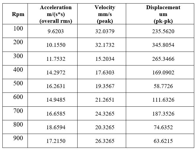
Thus the rpm of motor increases acceleration and displacementgetchange.ielessdisplacementthensteel.
5.5 Noise measurement for steel:-
Table
5.7
Table
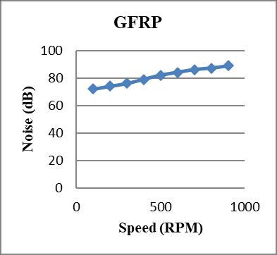
NoisemeasurementofGFRPmaterialislessthanthesteel
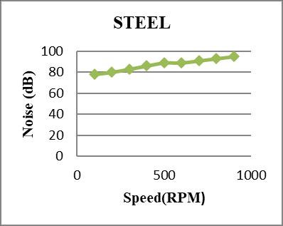
5.8 Graph of noise measurement for steel:-
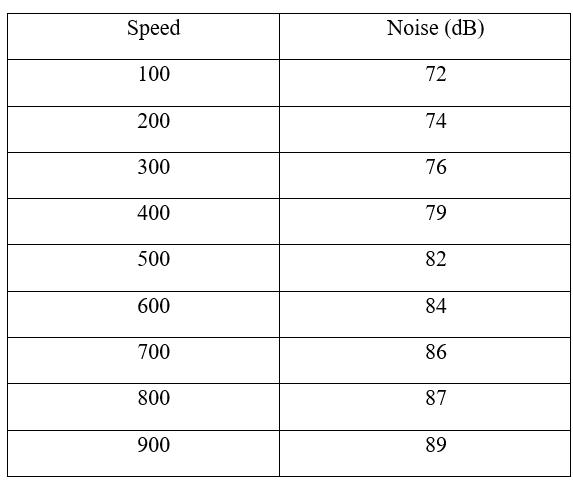
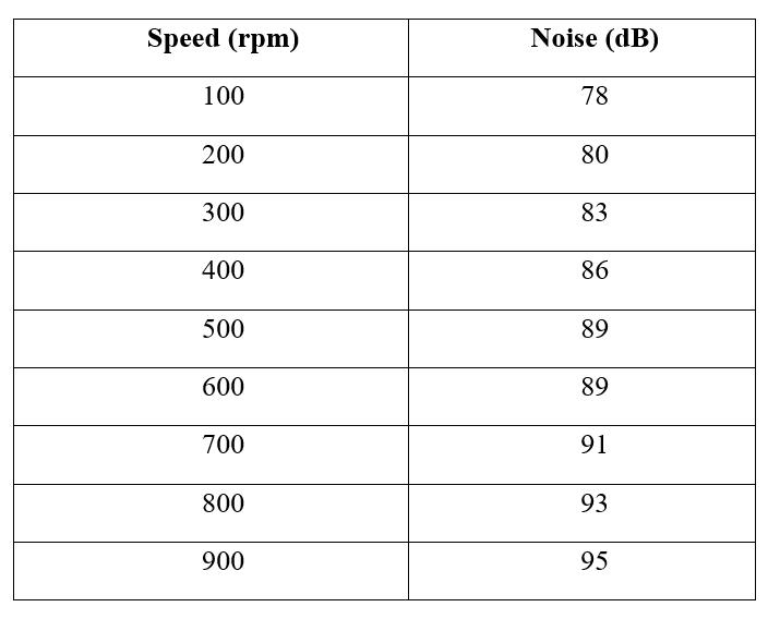

Noisemeasurementofsteelincreasesbymotorrpmbutit iscomparativelymorethanGFRPmaterial.
5.6
The FEA results table presents a comparison between the steel and GFRP material designs of the bracket. Upon analyzing the results, the following observations can be made:
ThesummarytableoftheFiniteElementAnalysis (FEA)resultsshowsthatthemaximumpressureobservedin the steel section is 61.834 MPa, which falls comfortably withintheacceptancecriteriaforthesteeldesign.Similarly, fortheGFRPdesign,theFEAindicatesamaximumpressure of 79.375 MPa, which is within the acceptance criteria specifiedfortheGFRPmaterial..
7. CONCLUSION
ByutilizingGFRPmaterial,asignificantweightreductionof upto66.67%isachieved,withthebracketweighingonly1.3 kgcomparedtotheconventionalmaterial.
• The first natural frequency of the GFRP design is determinedtobe37.413Hz,whichis2.4Hzlowerthanthe previoussteeldesignofthemountingbracket.
•Amongalltheanalyzedcombinationsoflayupangles,the bestanglecombinationselectedastheoptimalalternative was90degrees.
• Deformation is reduced by 90.23% when using GFRP materialcomparedtosteelmaterial.
• When assessing vibration in terms of motor rpm connection to probe acceleration and displacement, the GRFPmaterial exhibitslowerlevelscomparedtothesteel material.
REFERENCES
1. Dr.KRambabu,“StudyofDesignandAnalysisofAir Conditioner Compressor Mounting Bracket”, InternationalJournalofScienceandResearch(IJSR) ISSN(Online):2319-7064.
2. D.Singh, J.S.Saini,“Dynamic AnalysisofCondenser Assembly of Automobile Air Conditioning System Using CAE Tools”, Springer, J. Inst. Eng. India Ser. C (April–June2013)94(2):135–145.

3. Deshpande C., Ghatekar A., "Design of Compressor mountingBracketusingoptimization",International Journal of Advanced Information Science and Technology(IJAIST)Vol.13,No.13,May2013.
4. Doo-Ho Lee, Jeong- Woo Chang, Chan- Mook Kim," Optimal Shape Design of an Air Conditioner CompressorMountingBracketinPassengerCar",SAE NoiseandVibrationconference,2003.
5. Gabriel-petru anton, mihai paval, fabien sorel, “applicationonanupdatedfiniteelementmodelofan engine in the automotive industry” sisom 2011 and sessionofthecommissionofacoustics,bucharest2526may.
6. S.K. Loh a, W.M. Chin a, Waleed F. Faris, “Fatigue analysisofPackageTerminalAirConditionermotor bracketunderdynamicloading”,MaterialsandDesign 30(2009)3206–3216.
7. Doo-Ho Lee, Jeong - Woo Chang, Chan - Mook Kim, “Optimal Shape Design of an Air-Conditioner Compressor Mounting Bracket in a Passenger Car,” SAEInternational,2003-01-1667.
8. HongSukChang,“AStudyontheAnalysisMethodfor Optimizing Mounting Brackets,” SAE International, 200601-1480.
9. MahendraM.Gaikwad,“BracketDocument112978,” CoventryEngineers,UK.
