
Design & Development of Formula Student Chassis
Krunal Kania1, Aditya Verma2,
Rushang Babariya3 Jayendra Vasani41,2,3 Student, Automobile Engineering, L.D. College of Engineering, Gujarat, India
4Assitant Professor, Automobile Engineering, L.D. College of Engineering, Gujarat, India ***

Abstract - This research primarily focuses on the design & developmentoftheFSAEchassisframe.Thechassisisbasically a structural bracket to fit all vehicle subsystems like the powertrain, suspension, etc. It is a base with room for enhancement by reducing the weight & increasing the structural rigidity without hampering the performance of a high-speed vehicle.
Foraformulastudentteam,eitherspaceframeormonocoque chassis can be developed while keeping in mind the FS events’ guidelines. Besides achieving structural rigidity & torsional stiffness,anefficientdesignshouldalsomakeanimprovement in weight reduction & ease of manufacturing & manufacturability. A final spaceframe chassis completes all the checkboxes to make a vehicle with an important consideration of ergonomics (95th percentile) and driver inputs for the best drive positions. This research paper shows the criteria the team played with and the methods used to improve the final design.
Key Words: Chassis, Spaceframe, FSAE, Solidworks, Ergonomics, AISI 4130, Tube notching, Jigs & fixtures, Manufacturing.
1.CHASSIS
Thechassisisabaseforthedevelopmentofaformula-styled student vehicle. Designing an efficient chassis is a very important part of the vehicle's performance. It holds together all the subsystems like tractive systems, electric powertrain,suspension&wheels,driver&equipment,etc.
Mainly, the chassis is designed according to the rules & guidelinesofFormulaStudentEvents.Goalsforthedesign team were the chassis weight ≤ 28 kgs, better flexural strength, torsional rigidity 2000 Nm with ease of manufacturing&fabrication,takingintoaccountthedriver’s ergonomics&performanceduringdynamicevents.
FSAE chassis are made of spaceframe or monocoque Spaceframe chassis is a set of tubes welded together with triangulation for efficient load transfer across all tube members.Differentsizesanddimensionsareusedintubes according to the load acting on them. Materials like AISI 1080,AISI4130,etc.canbeusedforthetubes.
Ontheotherhand,monocoquechassisisasinglematerial bracketmadeupoflightweightmaterialslikecarbonfibreor aluminium sheets. They can also be made as semi-
monocoque where the rear structure is made up of tubes whilethefrontalpartconsistsofcarbonfibrelayupsasper theassemblyrequirements.
1.1 Design Methodology
For the season 2022-23, the spaceframe chassis was designed using SolidworksCAD modeling software.Asthe team had prior experience in spaceframe chassis design, therewasenoughroomforoptimizationbeforejumpingonto amonocoqueframedesign.ThematerialselectedwasAISI 4130 after comparing various available criteria to match seasongoalswhichwillbediscussedinupcomingtopics.
The table below shows the basic range of dimensions to choose for the tubes according to Formula Bharat 2022 rulebook.
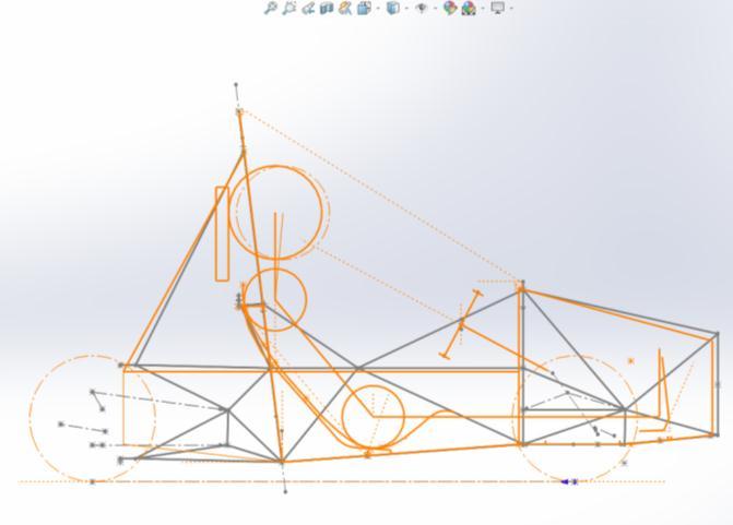
Initially, an envelope was designed with the focus to understandpositioningofsubsystemswithreferencetothe driver.Thishelpedtheteammarkthebasicsketchwithall reference points. Then, driver inputs using Ergo Jig were taken to initially set the angles for the roll hoops, and the maximumhorizontalcockpitspacerequiredwasdecided.
Then, secondary tubes are placed with reference to the suspensionhardpoints& nodes.All thetubessketched in software are made such that it satisfies triangulation conditionateverynode.Thedesignofavehiclechassis,for that matter, is going to be based on suspension points, powertrainlayout,driverpositioncontrols,safety,etc.
1.2
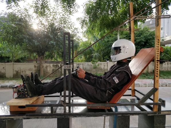
Ergonomicsofdriverplaysavitalroleintheperformance of the vehicle due better driving feel, and controls over steeringandbrakingsystem.Addingtothis,ergonomicsto anextentdefinestheweightdistributionofthevehiclewith regardstothedriver’sseatingposition.
Thedesignedergonomicjigfeaturedamockseatwiththe considerationsoffrontandmainrollhoops.Amockpedal box was added mark each driver, be it the tallest or the shortest, could easily have full pedal travel. The 95th percentile male percy (T 4.3.2) was used to design the referenceseatingpositionforthedriver.
Atlast,thetertiarystructuraltubesareattachedtoprovide smooth load transfer through the frame and increase the structural stiffness of the chassis. This is done through repetitiveanalysisoftheframestructureinANSYSsoftware.
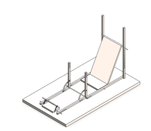
Oncewehadthejigmanufactured,therealergonomictest withthefinalizeddriversbegan.Theyweremadetositonthe jig and their feedbacks about the positions of different subsystems were noted. The input points regarding the inclinationangleofseat,thepositioningofthesteering,the pedalboxetc.wereinterpolatedandafinalseatingposition wasmockedwithallthedrivers.Aftertheseatingpositions
and inclination angle of the seat were finalized the design processfortheseatbegan.
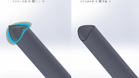
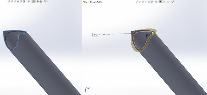
to minimize the manufacturing error. Every single tube is notchedonbothendsandthestepsusedare:
Step1:Isolate&extendsurfaceusingRuled/Extendtool
Theinclinationangleandseatingpositionhadlargescale implicationsonthevehicle’sdefiningparameters.Through theergonomictest,wecomparedanddeducedtheoptimum reclineanglewithrespecttothedrivervisibility,moreover this also affected overall frame length influencing vehicle dynamicconstraints. Table2showsthevariationsinMain Roll hoop height and total frame length according the differentdriverseatingposition.
Step
1.3 Software Methodology
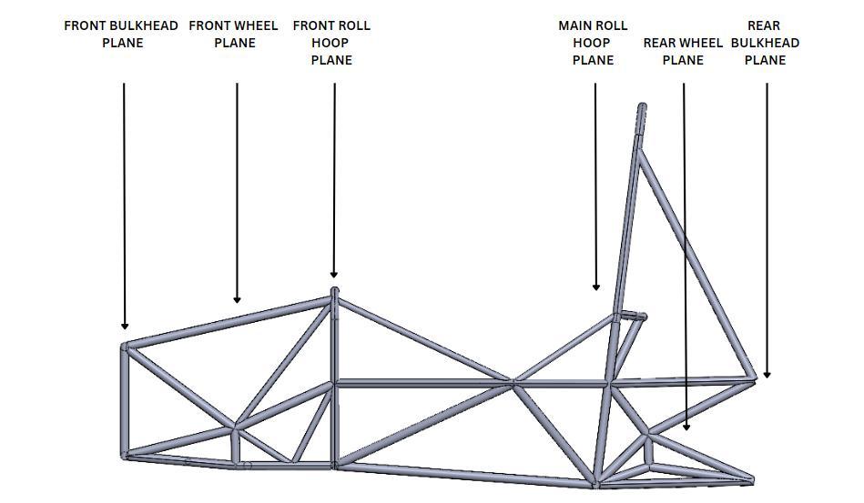
The software used during the designing process of the 2023 chassis were – SOLIDWORKS 2022. The process of designingthechassiswasstartedbycreatingreferencingthe planesatthedeterminedpositionsofthefrontbulkhead,the frontrollhoop,themainrollhoopandtherearbulkheadas showninfig.3.Acentralplaneisplacedtodividethechassis intohalfinbothYandZdirections.
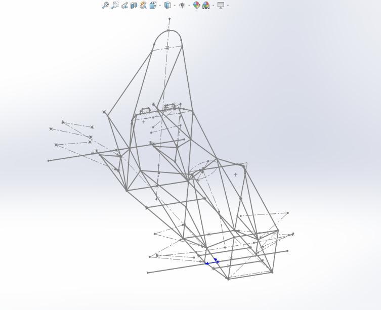
The suspension hard points were iterated with dynamics teams, then finalized and the triangulations for the same weresketched.Thenotchingofthetubeswasatrickyand lengthypartinthesoftwareasthenotchhavetobeprecise
1.4 Material Selection
Thematerialselectionforthechassistubesimpactsthe vehicle’sperformancetremendously.Thechassisstructure must be stiff to an appropriate extent, torsional rigidity, adequatelyloadbearingandprovidingoptimumnodalload transfer.Allthesepropertiesgreatlyimpactonthematerial selectedtomaketherollcage.
Thefirstthingsconsideredtoselectthematerialweretheir physical and mechanical properties like bulk modulus, flexuralrigidityE.I.,Poisson’sratio,density,yieldstrength and the ultimate tensile strength. Then after these properties,someauxiliaryconsiderationslikeprocurement period,costandlogisticsetc.
ThematerialthatwefinalizedwasAISI4130–(ahigh-grade chromium-molybdenum alloy) due its high structural properties and easy availability. The physical and mechanicalpropertytableforthe4130isshownbelow:
Table -2: Materialpropertycomparison
2. MANUFACTURING PROCESS
WhilemanufacturingaFSAEchassisprecision&strengthof weld are some of the main concerns. Strength can be controlled using the material of chassis, while precision is controlledusingtheaidoffixtures.TIGweldingprocesscan beoptedduetotheadvantageslikehigherweldstrength,no fluxrequirement,betterweldfinish&materialadaptability.
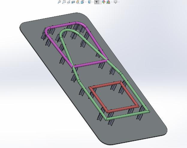
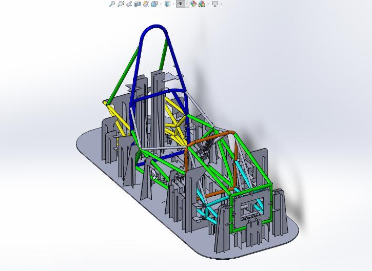
2.1 Design method
The fixture structure is divided into three parts: - The weldtable(baseplate),fixtures&fixturessupport.Thebase plateconsistsofslotswhereasthefixturesanditssupports consist of extended tabs which interlocks with each other. Thisassemblyconstrainsthemovementofthefixtureonthe baseplate.Thetubeisplacedonthefixtureperpendicularto theaxisofthetube.
2.2 Design considerations
The fixture components are made short vertically as it mightleadtobending.Thecircularcuthasslightlygreater diameter than the tube diameter so as to avoid tube misalignment during heat treatment. The FOS provided is 25.4±0.3mmtoreducefixtureerrors.
According to the design, two materials were taken into consideration, MS (mild steel) and MDF (Medium density fiber).Thetensilestrengthofmetal plateis380Mpa while thatofMDFsheetofsamedimensionis21MPa.Machiningof MDF sheet is tedious & withmoisture it gets swollen, also highlyflammable.WhilethedownsideforMSsheetisissueof bending&deformationwhilespotwelding attheirposition. Takingintoconsideration,theissueofdeformation,slightly thickerMSsheetswereused&hencetheteamplannedtogo withfixturesmadeofMildSteelsheets
Thefixtureanditssupportplatethicknessareimportant.We haveselected3mmMSsheet&baseplateis8mmthickMS sheet.AnyslotslasercutisdesignedwithFOSof±0.2mm. Themetalnearlasercutexpands&willnotcoolenoughto maintainthepreviousdimensions.Duringdesign,wehave avoidedangularcutsastheprecisionreduceswithincrease inangle.Inordertoreducethecomplexityfacedduringthe removal of fixtures post welding, the large fixtures were designedsuchthatthecorrespondingchassismembersare nottroubled.Thiswasachievedbydesigninglargefixturesin parts.
In order to keep the hard point of the tabs of A-arm in reference to each other a connecting fixture is added, similarly added for front-rear referencing. To prevent bendingofverticallylongfixtureforthemainrollhoop,we designedapyramidstructurethathelpedingivingadequate strengthaswellassupport.
3. CONCLUSIONS
The objective of this paper was to define a systematic approach to the design process for an FSAE Chassis. To
developacompetitivechassis,itisimportanttoemphasize onasystematicandstage-baseddesignprocess.Thedrafting processused,yieldedinadesignwithnotchesmuchmore precise at the triangulations than that observed in the previousversions.
Ergonomicshadahugeimpactinvehicle’sperformancedue to much more centralized and lowered seating position affectingCG,RollingInertiaandbalancingpolarmomentof inertia. It was found that a 5° inclination change in the seating position resulted in increment of 40mm – 60mm frame length due to a more reclined Main roll hoop and a biggerdriver’scockpitcompartment.
Design Considerations made for fixtures affects the manufacturability of the Chassis. The design methodology usedduringtubenotchinganddraftingfixturesresultedina muchmorepreciseChassisCADdraft.Alltheseparameters hadtremendousimplicationsontheChassisDesignProcess.
REFERENCES
[1] RuleT4.3.2,“FormulaBharatRulebook2023”
[2] E & O. E. Wilkinson Star Ltd 2017, “Guide to TIG welding”,WilkinsonStar
[3] WilliamF. Milliken,DouglasL.Milliken,MauriceOlley “ChassisDesign:PrinciplesandAnalysis[R-206]”
[4] Dr Timmins “MEEG 402-010 Chassis Design Report”, 2017
[5] B. J. Waterman, “Design and Construction of a SpaceframeChassis,”Des.Constr.aSpace-frameChass.,2011.
[6] P. N. V. Bala Subramanyam, B. Nageswara Rao, Y. Yashwanth Sai, K.Chandra Mouli, and C. H. Sreenivasa Pavansai, “Design and analysis of fsae chassis for safe conditions,”Int.J.Innov.Technol.Explor.Eng.,2019.


BIOGRAPHIES
Krunal Kania krunalkania@gmail.com
Student,Dept.ofAutomobileEngg. L.D.CollegeofEngineering-380015
Aditya Verma adityajverma29@gmail.com

Student,Dept.ofAutomobileEngg. L.D.CollegeofEngineering-380015
Rushang Babariya
rushang.babariya1111@gmail.com
Student,Dept.ofAutomobileEngg. L.D.CollegeofEngineering-380015