Design and Implementation of JPEG CODEC using NoC
MADIHA KAUSAR1, MOHAMMED ARSHAD MURTAZA2, KAUSER ANJUM31Assistant Professor, Dept. of E&CE, K.C.T. Engineeering College, Kalaburagi, Karnataka, India
2M.Tech Student, VLSI & Embedded Systems, Sharnbasva University, Kalaburagi, Karnataka, India

3Ph.D, Dept. of E&CE, K.C.T. Engineeering College, Kalaburagi, Karnataka, India ***
Abstract - An image compression and decompression system using NoC structure is developed and implemented. Due to the increasing demands of image transmission in computer and mobile systems, research on image compression has increased significantly. The JPEG (Joint Photographic Experts Group) standard is a commonly used method for lossless compression of digital images, especially those produced by digital photography. Digital images require a lot of storage space. The aim of this work is to design a VLSI architecture for basic sequential JPEG encoding and decoding processes. A codec that specifies howan image is compressed into a streamof bytes andthen decompressed back into an image is defined by the JPEG standard. To achieve high execution speed, the architecture makes best use of pipeline and parallelism principles. Providing effective on-chip communication networks, network-on-chip (NoC) is a new paradigm in complicated system-on-chip (SoC) designs. It enables scalable communication and decoupling of communication and computing. Data is sent over networks as packets. Data routing is primarily done through routers. The router architecture must therefore be effective, with lower latency and higher throughput; the effectiveness of the router architecture is assessed in a two-dimensional network topology. NoC is usedto speedup the image transfer process and thus provide a shorter processing time for transferring data over the network. The design is implemented using VerilogHDLandsimulatedinXilinxISEDesignSuite14.7.
Key Words: Image processing, Lossy Image compression, Image decompression, JPEG, CODEC, NoC.
1. INTRODUCTION
The reason why digital representation of the signal is more reliable than its analogue counterpart for processing, manipulation, storage, recovery, and transmission over long distances, even across the globe through communication networks, is why we are talking about digital networks, digital representation of images, movies,video,TV,voice,anddigitallibrariestoday.Digital technology has only recently been used to the transmission, recording, and processing of images, but it has quickly revolutionised many areas of image processing. Because it can carry out operations that are
challenging or impossible to carry out in the usual analogue format, the digital mode has largely supplanted analogue technology in various applications. So, both whentheyarecreatedandwhentheyarepresented,video signals are intrinsically analogue. There is an opportunity to transform these signals into digital format in between theseendpoints.
Foreffectivestorageandtransmission,digitalimagesmust be compressed because they have a significant amount of data. The need for digital picture storage, editing, and transporthasexplodedwiththeadventofdigitalcameras. These image files have a tendency to be enormous and take up a lot of RAM. A typical 640 x 480 color image has aboutamillionelements,buta256x256grayscaleimage has 65,536 to store. Standard broadcast television requires100to200Mbpsforvideoapplications,whereas low resolution applications like teleconferencing, remote surveillance, etc. just need a few megabits per second, whentheframerateandwordsizearedecreased,thedata rate can be brought down to a few tens of kilobits. Using picturecompressionmethodsatthesourcecouldresultin even more compression. At the destination, these compressed images are decompressed for viewing and analysis.
Many picture compression methods have been developed intherecentyears.Thesemethodsseektoreducethesize ofthephotosbysendingjustthenon-redundantdataasit is received. Other methods are inherently lossy. In this case,thereconstructedimagesareactuallyclosecopiesof the uncompressed originals. The original and reconstructed images' corresponding pixel values are different. As a result, compression may be accomplished without significantly affecting the visual image quality. A group of picture compression mechanisms are defined by the JPEG standard. The baseline sequential encoding scheme is the mechanism that is most frequently utilised. Thisapproachforlossycompression[1]isused.
Imagecompressionanddecompressiontechniquescanbe used to solve the digital picture transmission issue. In ordertospeeduptheforwardingofimagesandprovidea shorter processing time to transfer data through the network with a low latency, it can only transmit nonredundant data, as it does with NoC. Providing effective on-chip communication networks, a network-on-chip
(NoC) is a new paradigm in complicated system-on-chip (SoC)designs[2].Scalablecommunicationispossible,and communicationandprocessingcanbeseparated.
2. NETWORK ON CHIP (NoC)
The NoC technology was created to address bus short circuits. It is a method for creating a SoC design's intercore communication subsystem for intellectual property. Dedicated buses are used between communication resources in the system-on-chip communication strategy. It does not allow for any flexibility when it comes to communication requirements, thus planning is always a need. Using public transportation is still an option, but it hasthedrawbackofnotscalingupproperlyasthenumber of resources increases. By putting in place a network of switches, micro-routers, and resources for communication, NoC is intended to address these flaws. Future ASIC design has been suggested using the NoC design paradigm. The move to NoC-based solutions is being fuelled primarily by the present VLSI chip communication design methodology's inability for deep sub-micron chip fabrication technology. Technology scaling's detrimental effects on global connections, a higher reliance on fault mechanisms as feature 6 size reduces, and a growth in the use of parallel architectures are some of the factors contributing to NoC's rising popularity.
The manufacture of such integrated chips presents a number of design issues for NoC-based system-on-chips. First,a target NoCtopology thatcomplieswiththe design limitations and performance specifications. Second, the physical connection mechanisms for data transfer between processor cores are provided by the design of network interfaces to access the on-chip network and routers. The third consideration is selecting communication protocols appropriate for chips interconnect networks. Finally, the network of chips for the future will grow increasingly sensitive and prone to mistakes and failures as the magnitude and speed of technological progress rise. When communicating via chips, fault tolerance becomes crucial. For reduced wire routing, easier timing shutdown, higher running frequencies, and quick IP address changes, today's SoCs need on-chip network IP connectivity. System-on-chip success for next embedded applications depends on network-on-chipstechnology.
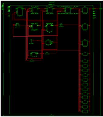
2.1 NoC ARCHITECTURE
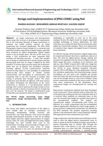
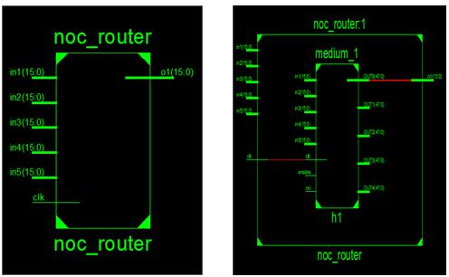
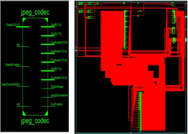
ThegeneralarchitectureoftheNoCisdepictedinFigure1. ProcessorElements(PE),NetworkInterfaces(NI),Routers (R), and Channels make up this system. Each PE has a networkinterfacethatconnectsittoanearbyrouter(NI). WE establish a logical connection between the network
and the IP core. The front end and the back end can be separated into two components. The UI handles requests to the IP core and is not aware of the network. The back end,whichmanagesnetworkprotocol,sortsandarranges packets, buffers, and aids the router with storage, is directly connected to the network. Data packets are transmittedbetweenthesourcePEandthedestinationPE. During transmission, the packet is transmitted over the network hop by hop in accordance with the router's choice.
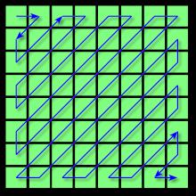
Switches and a buffer are also components of a router. Here,storeandforwardbufferingisapplied.Arouterand a related link make up a node. Links allow for data transmission on the network by transferring packets between routers. According to the chosen topology, it consists of a number of wires connecting various router networks; in this case, a 33 2D-Mesh NoC structure is employed. A router is in charge of transferring data utilising particular routing algorithms and control flow mechanismsfromsourcetodestination.
3. PROPOSED METHOD
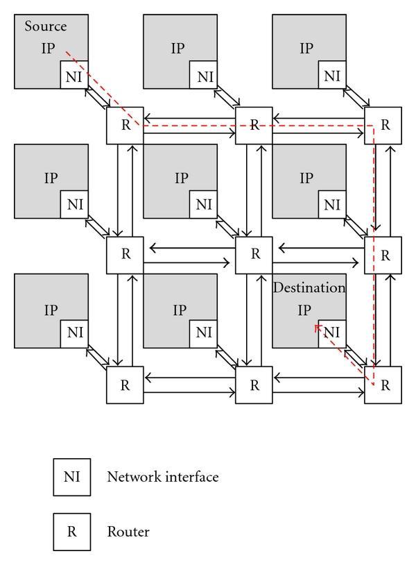
3.1 Encoding
1. Conversion of the image's color space: The image should first be transformed from RGB to Y′CBCR (or informally YCbCr). There are three parts to it: Y', CB, and CR.Y'representsthebrightnessofthepixel,whileCBand CR represent the colour (divided into blue and red components). The colour space utilised in digital colour television and digital video, including DVD video, is roughly the same. Higher compression is possible thanks to the Y′CBCR colour space conversion without considerablyloweringtheobservedimagequality.
2. Downsampling: People perceive image detail in image brightness(Y'component)substantiallymoreclearlythan in image hue and saturation due to the density of colour andlightsensitive receptorsinthehuman eye (Cband Cr components). Encoders can be made to compress images more effectively using this information. Reducing the spatial resolution of the Cb and Cr components is a commonnextstepwhenconvertingtotheY′CBCRcolour model (referred to as "downsampling" or "color subsampling").JPEGimagesareoftendownscaledatratios of 4:4:4 (no down-processing), 4:2:2 (by a factor of 2 horizontally), or (most frequently) 4:2:0 (by a factor of 2 both horizontally and vertically). The remaining press treatsY',Cb,andCrdifferentlybutquitesimilarly.
3. Block division: Each channel must be divided into 88 blocks after subsampling. This results in minimum coded units(MCU)blocksofsize88(4:4:4-nosubsampling),16 8 (4:2:2), or most frequently 16 16, depending on the colour subsampling (4:2:0). Macroblocks are what MCUs are known as in video compression. If the channel data does not represent an integer number of blocks, the encoder must insert some sort of dummy data into the remaining empty block region. Filling edges with a solid colour (like black) may result in ringing artefacts in the
border's visible portion. Such artefacts can be reduced (but not always entirely eliminated) via edge pixel rendering,and moreadvancededge-fillingtechniquescan alsobeapplied.
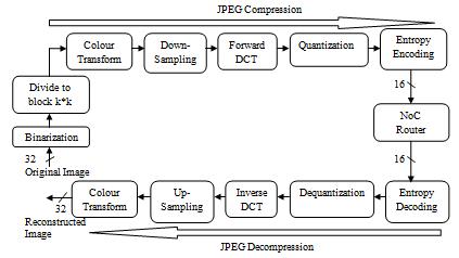
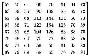
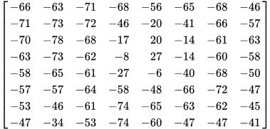
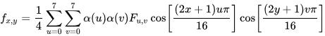
4. Discrete Cosine Transform (DCT): Next,anormalised two-dimensional Type II Discrete Cosine Transform is used to transform each 8 8 block of each component (Y, Cb,Cr)intoafrequencydomainrepresentation(DCT).One such888-bitsubimagemightbe,forinstance:
An8x8block'svaluesareshiftedfromthepositiverange to zero-centered before the DCT is calculated. Each starting block entry for an 8-bit picture falls between the [0,255]range.Theamendedrangeis[-128,127],anditis obtained bysubtractingthe midpointoftherange(inthis case,thevalue128)fromeachinput.Thesubsequentlevel of DCT processing will require less dynamic range thanks to this step. These values are obtained as a result of this step:

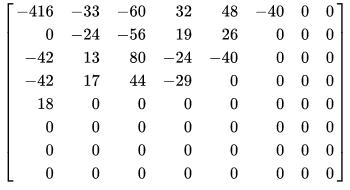
The two-dimensional DCT is the following phase, which resultsin:
rounded to zero and many others are transformed into tiny positive or negative values, which require a lot less bits to represent. Higher values for the quantization matrix's constituent parts lead to greater compression. According to the original JPEG standard, a typical quantizationmatrixisasfollows:
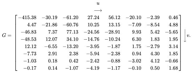
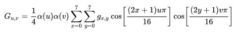
u is the horizontal spatial frequency of the numbers 0 through u plus eight. The integers 0 through v have a vertical spatial frequency of v. The normalisation scale factorthatmakesthetransformationorthonormalis(u)= 1/(2)1/2, if u = 0; 1 otherwise. The pixel value in (x,y) coordinates is gx,y. The DCT coefficient in coordinates is Gu,v (u, v). If we apply this transformation to the aforementionedmatrix,weobtainthevaluesshownbelow (roundedtotwodecimalplaces):Takenoticeoftherather largeentryintheupperleftcorner.Thebaseheightofthe whole block is determined by the DC coefficient, commonly known as the constant component. AC coefficients make up the remaining 63 coefficients (also calledACcomponents).
CalculatedarethequantizedDCTcoefficients.
ThebenefitofDCTisthat,ascanbeseenabove,ittendsto concentratethemajorityofthesignalinonecornerofthe result.BylesseningtheoverallsizeoftheDCTcoefficients, the subsequent quantization step emphasises this effect and creates a signal that is simple to effectively compress intheentropyphase.
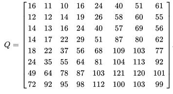
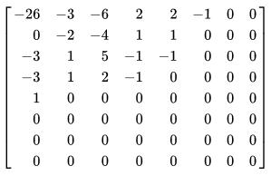
5. Quantization: The human eye is not very good at differentiating the intensity of high-frequency brightness variations, but it can detect very minor differences in brightness across a very big region. As a result, the information from high-frequency components can be reduced. To achieve this, just divide each component of the frequency range by its respective constant, rounding the result to the nearest whole number. If the DCT calculation is carried out with appropriate high accuracy, this rounding is the sole lossy operation in the entire process (apart from colour subsampling). As a result, many higher frequency components are frequently
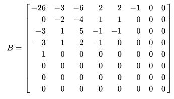
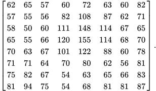
where Q is the higher quantization matrix, B is the quantizedDCTcoefficients,andGaretheunquantizedDCT coefficients. Combining the above DCT coefficient matrix withthisquantizationmatrixresultsin:
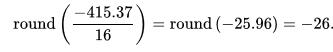
For instance, rounding to the next whole number and usingtheDCfactorof-415
Be aware that the majority of the subblock's highfrequencyelements(thosewithaspatialfrequencyofxor ygreaterthan4)arefilledwithzerovalues.
6. Entropy coding: This particular type of lossless data compression uses entropy coding. The run-length encoding (RLE) approach, which groups frequencies with a similar frequency together, adds zeros to the length
encoding, and then applies Huffman encoding to the remaining bits, is used to arrange the image components ina"zigzag"pattern.
(2DTypeIIIDCT),whichisthefollowingstep,isobtained by:
wherexisanarrayofintegersfrom0to8.Theintegers0 through 8 make up the pixel column y. For numbers 0 through u and up to 8, (u) is defined as above. In coordinates, Fu,v reconstructed the approximation coefficient(u,v).Thevalueofthereconstructedpixelin(x, y) coordinates is fx,y. As the original contained integers, rounding the result to integers yields the numbers in the illustration(delimitedby128)
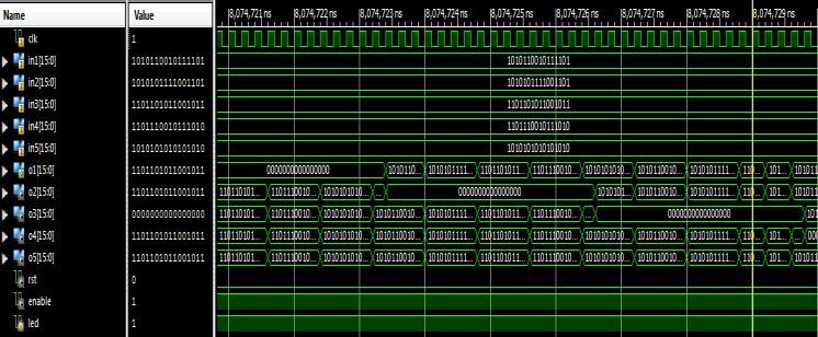
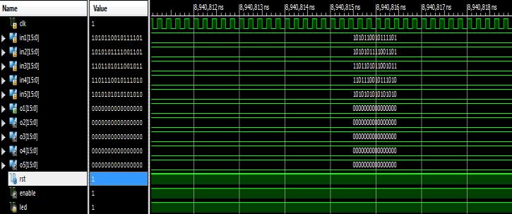
The NoC takes compressed image data as input, its function is to speed up the image transfer process and thus provideshorter processingtime forlow-latency data movementinthenetwork.
3.3 Decoding
There are various steps involved in decoding: All of the aforementionedstagesareperformedinreversetodisplay the image during decoding. Consider the DCT coefficient matrix(afteraddingtheDCcoefficientdifference)
thenmultiplyingeachentryby128
thenusingthequantizationmatrixandtheinputfromthe aforementionedresult
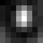
Hereyoumayviewthedecompressedsubimage.Generally speaking, the decompression process may produce values outside of the initial input range of [0, 255]. In this situation,thedecodermusttrimtheoutputvaluestokeep themwithinthisrangeinordertopreventoverflowwhile maintaining the decoded image's original bit depth. By subtracting the original from the uncompressed picture, the original subimage and the decompressed subimage can be contrasted (see also the images on the right), resultingintheincorrectsetofvaluesshownbelow:
Thiscloselyresemblestheupper-leftcorneroftheoriginal DCT coefficient matrix. The two-dimensional inverse DCT
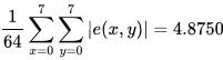
witha5numbersperpixelabsoluteerroronaverage.
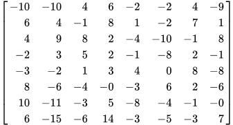
Thelowerleftcorner,whereitgrowsdarkerthanthepixel

right,iswheretheinaccuracyismostobvious.
4. PERFORMANCE ANALYSIS
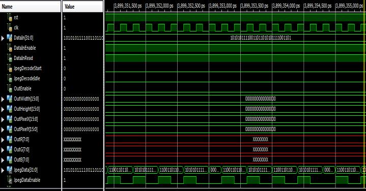
Verilog is used to build the design, and Xilinx ISE Design Suite14.7isusedtosimulateit.
5. CONCLUSIONS
The design and implementation of an image compression and decompression system utilising the NoC structure in Verilog HDL was effective. Thus, it provides faster data transmission through the network and is used to quicken theforwardingofimages.Futuredevelopmentwillinvolve expanding router architectures and building a productive
NoC. The NoC's FPGA version will also be done. On comparing with other different compression techniques, came to a conclusion that JPEG image compression and decompression algorithm is an efficient technique for to someextent.
REFERENCES
[1] Udaya Kumar H, Madhu B C, “Design and Implementation of Lossless Data Compression Coprocessor using FPGA” International Journal of Engineering Research & Technology (IJERT) ISSN: 22780181IJERTV4IS05083Vol.4Issue05,May-2015.
[2]MuhammadAtharJavedSethi,FawnizuAzmadiHussin, Nor Hisham Hamid, “ Survey of Network On Chip Architectures” Department of Electrical & Electronic Engineering, Universiti Teknologi PETRONAS, Tronoh, Perak,Malaysia,Sci.Int.(Lahore),27(5),4133-4144,2015.
[3] Moh’dAli Moustafa Alsayyh , Prof. Dr. Dzulkifli Mohamad &. Waheeb abu-ulbaa, “Image Compression Using Discrete Cosine Transform and Discrete Wavelet Transform” Journal of Information Engineering and Applications ISSN 2224-5782 (print) ISSN 2225-0506 (online)Vol.3,No.11,2013
[4] S. Deb, et al., “CMOS Compatible Many-Core NoC Architectures with Multi-Channel Millimeter-Wave Wireless Links”, Proceedings of Great Lakes Symposium onVLSI(GLSVLSI),3rd-4thMay2012.
[5] M. Bechtel Brabi and Dr. A. Rajalingam., ” Recent survey for Bi-Directional network on chip pipelined architecture” International journal of Advanced Research in computer science and Software Engineering, Volume-2, issue-12,December2012.