Design and Implementation of Isolated Zeta-Luo Converter for EV Charging Applications
1Student, Department of EE, JSS Academy of Technical Education, Noida, Uttar Pradesh

2Assistant Professor, Department of EE, JSS Academy of Technical Education, Noida, Uttar Pradesh
3Student, Department of EE, JSS Academy of Technical Education, Noida, Uttar Pradesh
4Student, Department of EE, JSS Academy of Technical Education, Noida, Uttar Pradesh ***
Abstract - This study presents a novel approach to designing a charger for battery electric vehicles (BEVs) by utilizing an enhanced Zeta-Luo converter. The Zeta-Luo converter, a modified combination of the Zeta and Luo converters,isspecificallytailoredtooperateduringindividual halvesofthesupplyvoltage,therebyimprovingpowerquality at the output. The key advantage of this design lies in its ability to enhance charger efficiency compared to other converters, while ensuring a consistent charging current for the battery. Both the improved Zeta converter and the Luo converteraresettooperateindiscontinuousconductionmode (DCM), which brings about cost and size reductions. The proposed model will be developed using MATLAB/Simulink.
Key Words: Zeta Converter, Luo Converter, Zeta-Luo Converter, Discontinuous Conduction Mode, EV Charging, PowerQuality
1.INTRODUCTION
DC-DCconvertershaveundergoneextensivedevelopment overthepastsixdecadesandhavefoundwidespreadusein industrial applications and computer circuits. With the electronicsindustrytrendingtowardslowvoltageandhighpower density, the technology has witnessed rapid advancementsandsignificanttransformations.TheDC-DC converter market is experiencing a faster growth rate of 7.5%comparedtotheAC-DCpowersupplymarket.Whilea simplevoltagedividercanserveasabasicDC-DCconverter, itsuffersfrompoorefficiencyandcanonlytransferoutput voltage lower than the input voltage. To overcome these limitations,themultiple-quadrantchopperemergedasthe nextstageinDC-DCconversion,aimingtoconvertDCenergy betweendifferentvoltagelevels.Thisbearssimilaritytothe functionofatransformerinAC-ACconversion.
In the current era, addressing environmental concerns, particularly pollution from hydrocarbon gases in transportation,hasbecomeacrucialissue.Topromotegreen transportation, electric vehicles are being vastly adopted Within electric vehicles, the DC-DC converter plays an important role in supplying power to auxiliary loads, necessitating efficient energy transfer between the high voltage and low voltage sides. This enables smooth operationandfunctionalityforvariousvehiclecomponents.
The proposed implementation incorporates synchronous rectification and soft-switching techniques, resulting in a cost-effective,flexible,reliable,andefficientsolution.
The advantages of the suggested BL converter for electric vehicle(EV)chargingencompasshigherefficiency,areduced component count, and the characteristic to work during bothpositiveandnegativesupplycyclesineitherZetaorLuo mode.Thisachievementismadepossiblebyintegratingtwo different converters and utilizing a cascaded PI controller that identifies the charging modes of the EV battery. The constantcurrentandconstantvoltagemodesareemployed forefficientbatterycharging,withthePIcontrollerensuring aconsistentchargingcurrentandvoltagethroughoutthese modes. In summary, the proposed BL converter offers a promisingsolutionforefficientandreliableEVcharging.
TheapplicationofacascadedPIcontrollerintheconstant current-constantvoltage(CC-CV)modeenablespreciseand stable charging of the EV battery, ensuring safety and reliability.TheintegrationofZeta-Luoconvertersduringthe twohalfcyclesallowsforimprovedefficiencyandreduced switchinglosses,resultinginenhancedpowerdensityand overall charger performance. Furthermore, the reduced number of components and devices in the converter contributestoamorecompactandcost-effectivedesign.The utilizationofdiscontinuousconductionmode(DCM)further enhanceschargerefficiencyandreducesitssizeandcost.
2.OPERATION OF ZETA LUO CONVERTER
The selection of the magnetizing inductance value is specifically tailored to enable the converter to operate in discontinuousconductionmode(DCM),amodeknownfor its ability to minimize conduction losses and maximize overallefficiency.Aninterestingaspectofthisdesignisthat bothconvertersutilizethesameoutputinductors,resulting in a notable reduction in the quantity of components and devicesusedintheconverter,resultinginasmallersizeand reducedcost.
Theconverter'scontrolmechanismisaccomplishedthrough the utilization of a cascaded proportional-integral (PI) controller.Thiscontrollerensurestheproperchargingofthe battery in both the constant current and constant voltage
(CC-CV) modes. The converter exhibits commendable performanceduringsteady-stateoperation,aswellasunder varying line voltage and load conditions. Moreover, it adherestotherecommendedpowerquality(PQ)regulations concerning mains power factor (PF), displacement power factor (DPF), and total harmonic distortion (THD) of the supplycurrent.
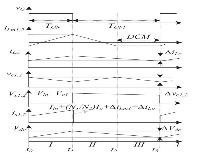
Duringthepositivehalf-cycleofthesupplyvoltage,theZeta converterassumestheroleofabuck-boostconverter,with theswitchS1beingactivated.TheintermediatecapacitorC1 is charged by the magnetizing inductance Lm1, while the outputdiodeDo1conducts,facilitatingtheflowofcurrentto the battery. Simultaneously, the Luo converter remains deactivated,andtheswitchS2remainsopen.
In the negative half-cycle of the supply voltage, the Luo converterfunctionsasaboostconverter,withtheswitchS2 being activated. The magnetizing inductance Lm2 charges theintermediatecapacitorC2,whiletheoutputdiodeDo2 conducts, allowing current to pass through to the battery. Throughoutthisperiod,theZetaconverterisinactive,and theswitchS1remainsopen.
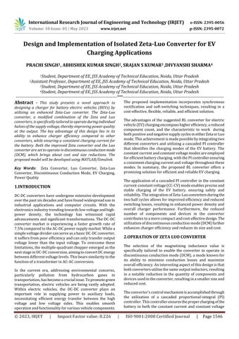
Within this time frame, the voltage across capacitor C1 experienceslineargrowth.Oncethevoltageacrosscapacitor C1 reaches its peak value Vp at time t3, the switch S2 is triggeredtoturnON.Thisactioninitiatestheworkingofthe Luoconverterinthenegativehalf-cycle.
Interval-I[t0–t1]:Withinthistimeframe,theLuoconverter is active, and switch S2 is in a conducting state. The magnetizinginductanceLm2graduallyaccumulatesenergy fromthesourceviadiodeDn.AsdepictedinFigure3(c),the voltage across capacitor C2 diminishes while the current passes through the output inductor Lo2 on the secondary side.Thismodeendsattimet4whenswitchS2goesinOFF state TheoutputdiodeDo2remainsnon-conductive.
Interval-II[t1–t2]:Inthistimeinterval,switchS2goesinthe OFFmode,andtheconductionofdiodeDo2commences.The stored energy within the magnetizing inductance Lm2 is dischargedthroughcapacitorC2,supplyingpowertooutput diode Do2 and the secondary winding of the transformer. Simultaneously, the output dc-link capacitor initiates its chargingprocess throughinductanceLo,while the battery currentisregulatedintheconstantcurrent(CC)mode.
Interval-III [t2 – t3]: During this time period, switch S1 remainsinaninactivestate,leadingtheconvertertoenter the discontinuous conduction mode (DCM). The combined currentsflowingviaLm1andtheinductorattheoutputend Lo result in a net zero current through diode Do1, as illustratedinthediagram.
SimilaroperationalcharacteristicscanbeobservedintheLuo mode which occurs in the negative half of the supply, as depictedinFigures1and2.Theprimarydistinctionliesin the DCM operation of the Luo converter, where the magnetizing inductance exhibits zero current. Figure 4 providesthecorrespondingwaveformsofvariousswitching elementsthroughoutacompleteswitchingcycle.
3.DESIGN AND SIMULATION
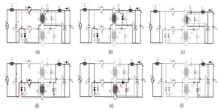
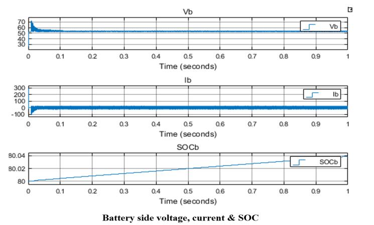
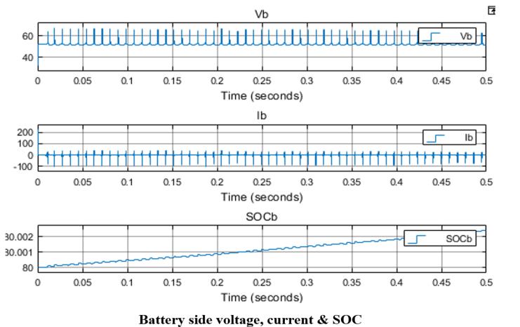
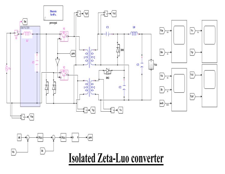
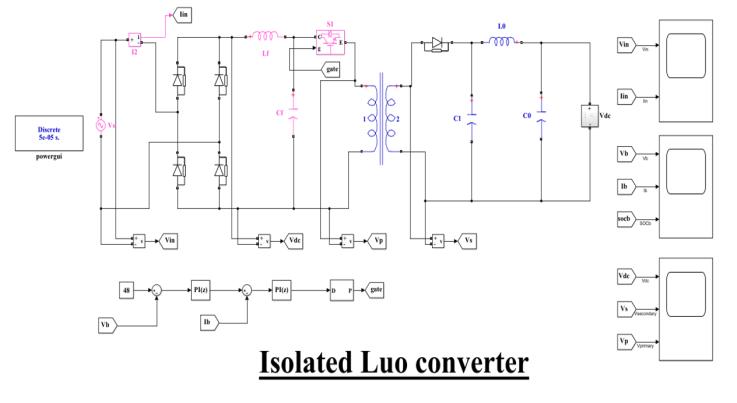
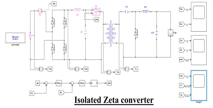
Toevaluatethesuitabilityoftheconceptforelectricvehicle applications,simulationmodelsareemployedtoanalyzethe performance on different electric loads. These models simulatereal-worldconditionsandaimtoprovideaccurate predictions.Below,youcanfindtheSIMULINKmodelsforan electricvehicle(EV)batterychargerutilizingisolatedZeta, isolatedLuo,andisolatedZeta-Luoconvertertopologies.
Thepurposeofconductingthesesimulationsistodetermine the most suitable converter topology for EV charging applicationsbasedonthedesiredoutputrequirements.
4. CONCLUSION
An EV battery charger based on the discontinuous conductionmode(DCM)wascreated,utilizinganenhanced power quality (PQ)-based BL isolated Zeta-Luo converter. ThisinnovativedesigncombinesthefunctionalitiesofZeta and Luo converters, with each operating during distinct
halvesofthesupplyvoltage.Bysharingtheoutputinductor, this converter achieves higher efficiency compared to previousconverterdesigns,leadingtoreducedchargercosts and a smaller form factor. Furthermore, the inclusion of output inductances in the two converters ensures a consistent current for charging the battery, which is advantageouscomparedtousingonlyZetaorLuoconverters forbothcycles.Theimplementationofgatedriveandcontrol is simplified as both devices receive similar pulses during operation.Thedistortioninthesourcecurrentwasfoundto beminimal,dependingonthechargingmode.Overall,this new isolated converter topology represents an improved solutionforEVbatterycharging,offeringenhancedpower qualitycharacteristics.
REFERENCES
[1] Jerrold Foutz, "Switching-Mode Power Supply Design TutorialIntroduction",SMPSTechnology, http://www.smpstech.com/tutorial/t01int.htm, accessed: Mar2012.
[2]MarianK.Kazimierczuk,"Pulse-widthModulatedDC-DC PowerConverters",Edition,Wiley.
[3] William P. Robbins, Tore M. Undeland, Ned Mohan, "PowerElectronics:Converters,Applications,andDesign", 3rdEdition,Wiley.
[4] B. Singh and R. Kumar, "BLDC Motor-Driven Solar PV Array-Fed Water Pumping System Employing Zeta Converter,"IEEETrans.IndustryApplications,vol.52,no.3, pp.2315-2322,May-June2016.
[5] Y. Jang and M. M. Jovanovic, "State-of-the-art, singlephase,activepower-factor-correctiontechniquesforhighpowerapplications–anoverview,"IEEETrans.Ind.Elect., vol.52,no.3,pp.701-708,June2005.
[6] Sanjeev Singh, Bhim Singh, Kamal Al-Haddad, and Ambrish Chandra, "Comprehensive Study of Single-Phase AC-DC power factor corrected converters with highfrequency isolation," IEEE Trans. Industrial Informatics, vol.7,no.4,pp.540-556,Nov.2011.
[6]AbrahamI.Pressman,"SwitchingPowerSupplyDesign", SecondEdition,McGraw-Hill,PublicationDate:Nov1997.
[7] Chris Mi and Hua Bai, "Comparison and evaluation of different DC/DC topologies for plug–in hybrid electric vehicle chargers," Int. J. Power Electron, vol. 4, no. 2, pp. 119–133,Feb.2012.
[8] Chester Simpson, "Linear and Switching Voltage Regulator Fundamentals", National Semiconductor, http://www.national.com/assets/en/appnotes/f4.pdf, accessed:Mar2012.
[9]V.Bist,S.Singh,G.Bhuvaneswari,andB.Singh,"Power Factor Corrected Zeta Converter Based Improved Power Quality Switched Mode Power Supply," IEEE Trans. Ind. Elect.,vol.62,no.9,pp.5422-5433,Sept.2015.