Material optimization and analysis of Composite propeller shaft and its behavior under Torsional and Bending Loading: A Research
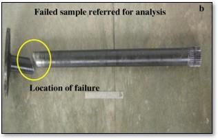


Abstract – Automobileswhichcorrespondtodesignwith rear wheel drive and front engine installation has transmissionshafts.Theweightreductionofthedriveshaft can be achieved without increase in cost and decrease in qualityandreliability.Toachievesuchcriteria,weneedto designcompositedriveshaftwithlessweighttoincreasethe firstnaturalfrequencyoftheshaft.Thisworkdealswiththe replacement of a conventional steel drive shaft with High Strength light weight Composite shafts for an automobile application.InthisStudy,thedriveshaftofavehiclewillbe considered for testing and analysis. The modeling and analysiswillbeperformedusingCREOandANSYSsoftware respectively.Theanalysiswillbedoneforboththematerials.
Key Words: Torsional Strength, Drive Shaft, Optimization, FEA, Matrix Composites.

1. INTRODUCTION
1.1 Drive Shafts: Driveshaftsaremechanicalcomponents that are widely used in vehicle powertrain systems to transmittorqueandrotationbetweendifferentcomponents whicharenotinlineorcannotbeconnecteddirectly.Drive shaftsmusthaveelements, suchassplines,gears,grooves andoilgalleries,mountedormanufacturedontotransmit powerordeliverlubricant.Theshaftmustbestrongenough tobearthestressforshorttermloading,thestressstateis quasi static and the drive shaft should be designed to preventplasticdeformation;forlongtermloading,thestress stateisdynamictherefore theshaftmustbedesignedfor millionsofstresscycles.Itisadriveshaftthatisdesignedfor applicationsthatcallforincreasedhorsepower,soyoucan hit the road with confidence. Reduced overall weight and rotatingmass,deliversimproveddrivingperformanceand Providesquickeracceleration.
1.2 Failure modes of Shaft
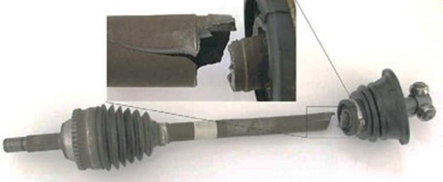
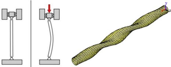
Themainpurposeofshaftisthatitmusttransmitthetorque from transmission of Differential Gear Box. As its aim to transferspeed,itshouldbecapableofrotatingatfastspeed as required by the vehicle. It must operate through constantly changing angles between the transmission, differential andaxels.Due toitsfunctional conditions, the shaft is subject to torsional and bending forces under operatingconditions.
1.3
1.3.1
1.3.4 Buckling Failure
1.4 Problem Definition
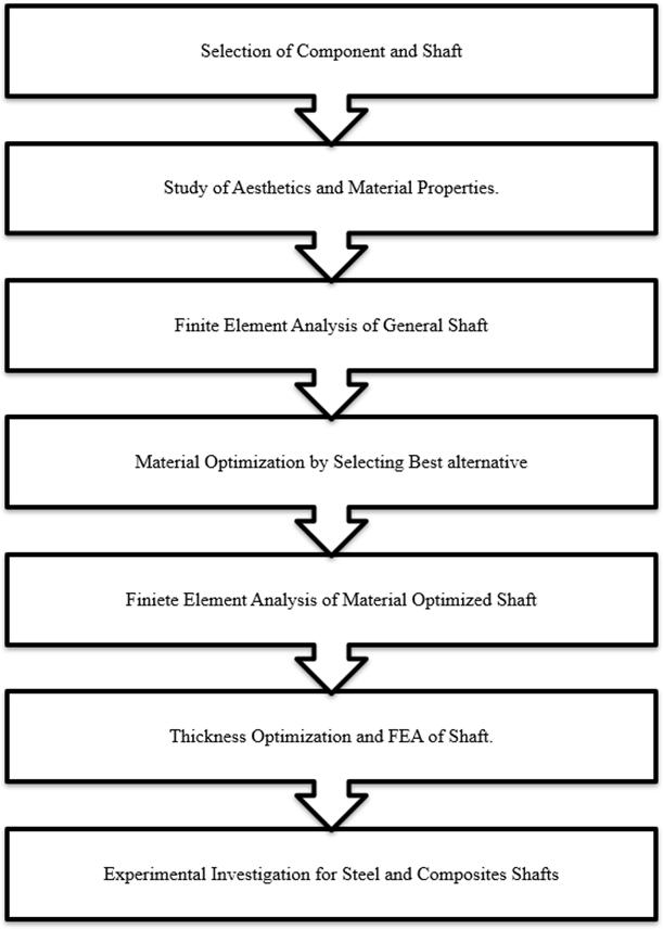
“Todesignandanalyzetheautomobiledriveshaftbyusing matrix composite material so as to increase the torsional strength.”TheDriveshaftismadeofheavy-dutysteeldueto itstremendousamountofstrengthandapplicability.Butto overcome thisstrength,the material quantityisincreased which affects the torsional stability of the component, therebyaffectingthepowertransmissioncapacity.Hence,in thiscase,anattemptismadetodesignanalysisandoptimize thedriveshaftwhichismadeofsteel.Theobjectivesofthis researchare,
-FiniteElement Stress and Deformationanalysisto obtain thetorsionalstrengthofmaterial.

-ToselecttheBestpossiblematerialsoastoreplaceitwith theSteel.
-Todeterminethetorsionalstrengthofcompositematerials.
-ToreducetheweightofShaft.
-ToincreasetheStrengthofShaft.
2. Literature review
[1]Theshaftmadeofsteelandfabricreinforcementadded to the shaft made the shaft advantageous in weight reduction.
[2] The forged steel shafts have its own advantages and disadvantages in implementation and use. The paper describesthechemicalcompositionandmaterialproperties offorgedsteel.
[3]Theshaftmeetswiththefractureduetobumpingnature of road condition. The material discuss in the paper is 42CrMo4gradeofsteel.
[4]Theparametersofimpactarediscussedalongwiththe experimentaltestofIzodTest.
[5][6]Theshaftisdesignedusingcarbonfibreandvarious failurecriteria’swhichhelpindesigningofshaft.
[7] Shaft of Maruti Suzuki Omni and various Design ConsiderationsofShaftsubjectedtodifferentmoments.
[8]Conductsthebucklinganalysisofcompositedriveshaft forautomotiveapplications.
[9] The work carried out on the composite drive shafts whichareusedintheautomotiveapplications;fabrication techniques and materials used in the fabrication of compositeshafts,finiteelementanalysisoncompositeshaft andsteelshaft.
[10]. An attempt is made to evaluate the suitability of composite material such as E-Glass/Epoxy and Carbon/Epoxyforthepurposeofautomotivetransmission applications.
[11]. The research work is to replace conventional steel material two-piece three universal joints drive shaft with composite material single-piece drive shaft. Single-piece driveshaftisdesignedinSolidEdgeandPro-Esoftware.
[12] The modeling of composite drive shafts is made in analysissoftwareANSYS.
[13]Intheprocessofdamageaccumulation,thedamagefirst appearsatthestressconcentrationoffibrematrix.
[14] In the present work, Composite propeller shaft of E Glass/Epoxy is made identical as steel propeller shaft of same torque carrying capacity. The propeller shaft is designedfor2Tontruckwithtorquecapabilityof1500Nm.
[15]Thetensileandtorsionexperimentswerecarriedouton 3Dbraidingcompositeshaftswithdifferentbraidingangles, andAEwasusedtomonitorthe damage evolutionduring theexperiments.
3. Methodology
4. Component Specifications

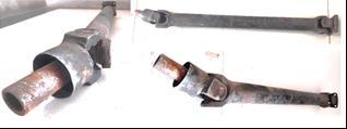
Inthiscasestudy,thedesignandanalysisofpropellershaft isconsidered.Theshaftconsideredforcasestudyisselected fromMarutiOmni.MarutiSuzukiOmniis5seatingCapacity vehiclesdependingontheseatingarranged.Specificationsof cararegivenin Table 1.InthisstudyMarutiOmnicardrive shaftistakenforstudy.Fortheunderstandingloadingand boundary conditions. The Current Shaft is made of Steel SM45C.SM45Cisquenchedandtemperedsteel;itbelongsto lowcarbon,lowcarbonchromium,molybdenumandnickel. The chemical composition and material properties are shownin Table 2 And Table 3
5. Loading Constraints
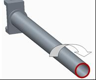
As the maximum engine speed is 3400 rpm, hence, the maximum power transmitted by the engine is 6KW, the torque transmitting capacity of the engine is 59.82N.m, hencethesameisconsideringasappliedtorqueasshownin Figure 1.
Thetorsionalforceistheforcewhichisrequiredtoproduce theestimatedtorque.HenceTorsionalForce(F1)generated byengineduringrunningis2790Ntoamarginconsideredas 3000N(Safety)asshownin Figure 2
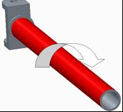
Itisthespeedoftheshaftwhichisrunningtotransmitthe speed. As the engine speed is 3400 rpm, the rotational velocityisconsideredthesame.TheAngularVelocity()is 356.04Rad/Sec.asshownin Figure 3
5.4 Shaft Subjected to Bending Moment
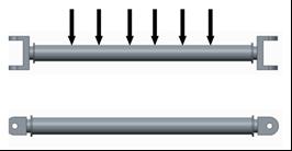
Considering the shaft subjected to its self-weight of 4 Kg whichisequivalentto40N.HenceBendingMoment,(M)is consideredas5x105N.mm.asshownin Figure 4
5.5 Torsional Buckling
Torsionalbuckling(Ǿ)capacityofshaftTorsionalbuckling (Ǿ)capacityofshaftas433N.mm
6. Application of Finite Element Analysis

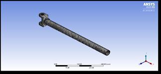
The Shaft model is first modeled in the Creo software of Version3.0.TheCreofileisfurthersavedinIGEStocallin Ansys. ANSYS meshing is automated high-performance meshing as shown in Figure 5. It produces the most appropriate mesh for accurate, efficient multiphasic solutions.AccuracyobtainedfromanyFEAmodelisrelated tothefiniteelementmesh.
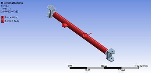
The bending buckling is produced due to the weight occurringontheshaft.Inthecurrentcasestudy,theweight of shaft is 40N, hence this is considered as the buckling weight.Thebucklingisproducedduetothecoupleactingof 40N.Theapplicationofbucklingforceisdescribedin Figure 7.
6.1 ANSYS Setting for Torsional Loading
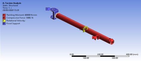
TheComponentissubjectedtoStatic,Sudden,andTorsional loadingonvarioussectionsasexplainedindetailinTable4. The Values are substituted on their respective Section as showninthe Figure 6.
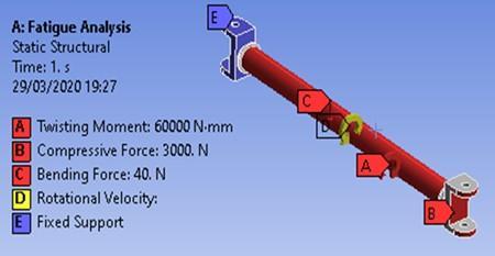
Twistingmomentisappliedof60000Nmm.Compressive force of 3000N and bending force by self-weight of 40N. Shownin Figure 8.
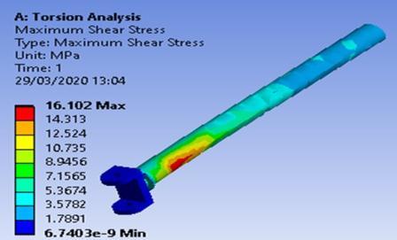
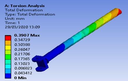
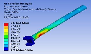
The FEA is done all of the above loading constraints on SM45C to determine the Equivalent Stress of 31.122 MPa shown in Figure 9., Deformation of 0.3907 mm shown in Figure 10. andShearStressof16.102MPashownin Figure 11. wasproduced.
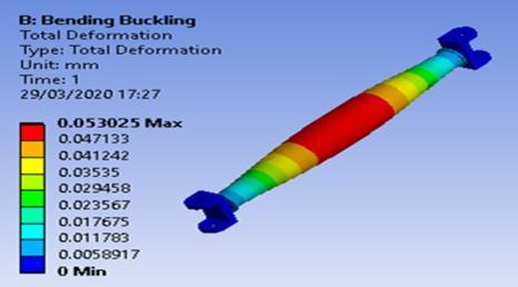
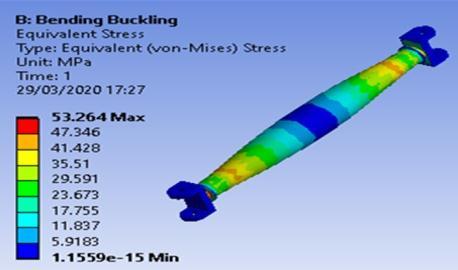
The Maximum Equivalent Stress produced after buckling loadingforSM45Cwas53.264MPashownin Figure 12.and Deformationof0.053025mmshownin Figure 13.
Varioustypesofmaterialscanbeusedfortheshaftwhich aremadeofAluminummatrixcompositescomponentsdue to its high yield strength but the and low weight. These materialsarelightinweight,hencecanbeimplementedfor ReductioninoverallweightoftheassemblyandReduction inmaterialcost.Henceinthecurrentstudy,themetalmatrix ofAluminum 2024(AL2024)isbeenusedasreplacement material.MechanicalpropertiesofAL2024aregivenin Table 4.

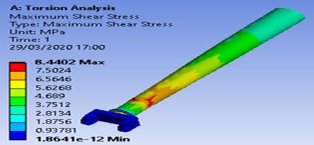
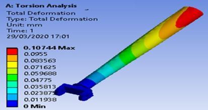
The FEA is done all of the above loading constraints on AL2024 to determine the Equivalent Stress of 14.46 MPa shownin Figure 14.,Deformationof0.10744mmshownin Figure 15. andShearStressof8.4402MPashownin Figure 16. wasproduced.
8.2
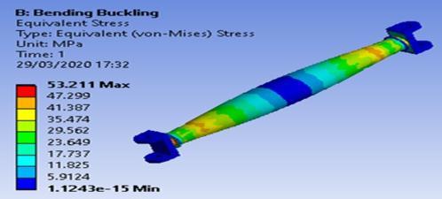
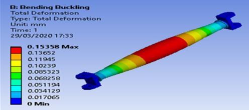
The Maximum Equivalent Stress produced after buckling loadingforAL2024was53.211MPashownin Figure 17.and Deformationof0.15358mm.shownin Figure 18.
thispaper.MechanicalpropertiesofCarbonfiberarestated in Table 5.

Polymermatrixcompositesarewidelyusedintheaerospace and automobile industries due to its light weight. These materials possess high yielding strength and less fracture damage. Due to its strength and weight, this material is foundtobeimplemented.Carbonfiberisstrongcomposite polymermaterialthatisusedforcasestudyoftheshaftin
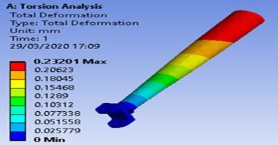
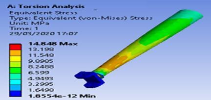
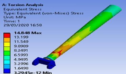
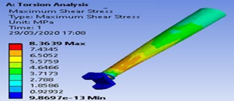
The FEA is done all of the above loading constraints on CarbonFibretodeterminetheEquivalentStressof14.848 MPashownin Figure 19.,Deformationof0.23201mmshown in Figure 20. andShearStressof8.3639MPashownin Figure 21.wasproduced.
9.2 FEA for Buckling Loading subjected to Carbon Fibre
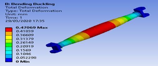
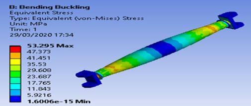
The Maximum Equivalent Stress produced after buckling loadingforCarbonFibrewas53.295MPashownin Figure 22. andDeformationof0.47069mmshownin Figure 23.
10.2 Comparison of Results for Bending Buckling
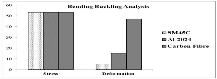
As we can see from the Figure 25, for all the loading conditions,thestressproducedforsteel,Al2024andCarbon Fibre is similar. Hence, we can say that, with respect to bendingload,thestrengthofshaftwillbesameforallthe material.Referringto Table 7,thedeformationislowestin steelduetoelasticitypropertyofsteel. Thedeformationin other two materials of Al2024 and Carbon Fibre, even though,morethanthesteel,butitislessthanthemagnitude of1.Hencewithrespecttobending,thematerialsatisfiesthe deformationcriteria.
10. Result and Discussions

10.1 Comparison of Results for Torsional Loading
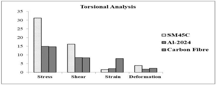
The resultant stress produced is lesser for all Aluminum MatrixandPolymerMatrix materialsasshownin Table 6. Hence, in strength criteria for equivalent stress, the optimizedmaterialsofAl2024andCarbonFibresatisfythe condition. The Shear stress produced is lesser for Al2024 and Carbon Fibre. Hence, in shear strength criteria the optimizedmaterialsofAl2024andCarbonFibresatisfythe condition. The deformation produced is lowest in case of Al2024 and moderate in case of carbon fibre. The deformationisfoundhighestinSteelmaterial.Strainisthe changeinshapeofobject.Withrespecttotheabovegraph, the strain is maximum in Polymer material, but as the deformation is low here, hence we can consider that the changeisshapewillalsobemoderate.Shownin Figure 24
10.3 Comparison of Results for Fatigue Life Analysis
With respect to the working hour’s life, the life of carbon fibreandAl-2024ismorethanthatofsteel.Asrepresented in Table 8. Henceuseofmatrixcomponentswillincreasethe life of shaft. Fatigue damage is the design life divided by availablelifeofcomponent.Thisresultmaybescoped.The defaultdesignlifeissetbycontrolpanel.ForFatigue,values greaterthan1indicatesfailurebeforedesignedlife.Hence, accordingtodamagecriteria,allthethreematerialsaresafe.
Biaxialityindicationissaidtobetheprincipalstresssmaller in magnitude divided by larger principal stress with the principalstressnearesttozero.Hence,withthemoreratio themoreeffectivematerial.Henceallthethreematerialsare safeunderworking.
Material,MaterialsToday,ElsevierPublication,2018;10001007.
[2] Godec M, Mandrino D, Jenko M, Investigation of the fractureofacar’sdriveshaft,JournalofEngineeringFailure Analysis,ElsevierPublication,Volume16,2019;1252-1261.
[3] MadhuK,DarshanB,ManjunathK,BucklingAnalysisof CompositeDriveShaftforAutomotiveApplications,Journal of Innovative Research and Solutions, A Research Gate Publication,VolumeNo.1A,IssueNo.2,Jun2013;63‐70.
11. Conclusion
Inthispaper,thematerialoptimizationofshaftmadeSMC45 Steelisdonewiththereplacementofaluminumandpolymer matrix components. All the loading constraints have been studiedandappliedtodeterminetheloadingconditionsthat canbeusedforFEA.Forfiniteelementanalysis,theultimate loadingconditionof1.2Factorofsafetyhasbeenconsidered. FEA is done in Ansys software for determination of EquivalentStress,deformationandstrainproducedinthe material for all the loading conditions. The optimized material of Aluminum and Polymer matrix satisfies the strengthcriteriaofStressandshear,hencecanaccordingto thisconditiontheexperimentissuccessful.UseofAl-Matrix andPolymermatrixmaterialisalsooptimalasitreducedthe cumulativeweightasreductionof40%withimprovementin strength. This reduction in weight of vehicle can lead to economic value of product as the raw material and manufacturingcostcanbereduced.
12. Acknowledgments
The Research Paper is outcome of guidance and moral supporttomethroughoutmywork.ForthisIacknowledge andexpressmyprofoundsenseofgratitudeandthanksto everybodywhohavebeenasourceofinspiration.Firstand foremost,IoffermysincerethankswithtoProf.S.S.Kathale (H.O.D)MechanicalEngineeringDepartment,forproviding helpwheneverneeded.
TheconsistentguidanceandsupportprovidedbyProf.J.S. Shitoleisverythankfullyacknowledgedandappreciatedfor thekeyroleplayedbyhiminprovidingmewithhisprecious ideas, suggestions, help and support that enabled me in shapingmyresearchwork.Iwouldliketothankmyfamily forprovidingmemoralsupportinmywork.
13. References
[1] ElanchezianC,RamnathB,RaghavendraK,Murlidharan M, Rekha G Design and Comparison of Strength and Efficiency of Drive Shaft made of Steel and Composite
[4] Belawagi G, Shrishail B, Satwik V, Finite Element & Experimental Investigation of Composite Torsion Shaft, International Journal of Engineering Research and Applications(IJERA),AResearchGatePublication,Volume3, Issue2,April2013;1-8.

[5] Das S, Mukhopadhyay G, Bhattacharyya S, Failure analysisofaxleshaftofaforklift,JournalofCaseStudiesin EngineeringFailureAnalysis,ElsevierPublication,Volume 03,2015;46-51.
[6] Kumar A, Jain R, Patil P, Dynamic Analysis of Heavy Vehicle Medium Duty Drive Shaft Using Conventional and CompositeMaterial,conferenceSeries:MaterialsScienceand Engineering,IOPPublishing,Volume149,2016;1-11.
[7] Reddy P and Ch. Nagaraju, Weight optimization and FiniteElementAnalysisofCompositeautomotivedriveshaft for Maximum Stiffness, 5th International Conference of Materials Processing and Characterization (ICMPC 2016), MaterialsToday,Elsevier,Volume04,2016;2390-2396.
[8] Gong L, Gao X, Yang H, Liu Y, Yao X, Design on the driveshaft of 3D 4-Directional carbon fiber braided composites, Journal of Composite Structures, Elsevier Publication,Volume203,2018;466-473.
[9] NadeemS,GiridharaG,RangavittalH,AReviewonthe design and analysis of composite drive shaft, Materials Today,ElsevierPublication,Volume05,2018;2738-2741.
[10] Prasad A, Ramakrishna S, Madhavi M, Experimental Investigations on Static and Dynamic Parameters of Steel andCompositePropellerShaftswithanIntegratedMetallic Joints, Materials Today, Elsevier Publication, Volume 05, 2018;26925-26933.
[11] ZhaoG,ZhangL,WangB,HaoW,YingL,HHT-basedAE characteristicsof 3D braidingcompositeshafts, Journal of Polymer Testing, Elsevier Publication, Volume 79, 2019; 106019.
[12] ZhaoL,XingQ,WangJ,Shen-longLi,ZhengS,Failure and root cause analysis of vehicle drive shaft, Journal of
EngineeringFailureAnalysis,ElsevierPublication,Volume 99,2019;225-234.
[13] Liu Y, Lian Z, Xia C, Qian L, Liu S, Fracture failure analysisandresearchondriveshaftofpositivedisplacement motor, Journal of Engineering Failure Analysis, Elsevier Publication,Volume106,2019;104145
[14] HaoW,HuangZ,ZhangL,ZhaoG,LuoY,Studyonthe torsionalbehaviorof3-Dbraidedcompositeshafts,Journal of Composite Structure, Elsevier Publication, Volume 229, 2019;111384.
[15] Shokrieh M, Hasani A, Lessard L, Shear buckling of a compositedriveshaftundertorsion,JournalofComposite Structure,ElsevierPublication,2018;63-69.
[16] https://www.cardekho.com/maruti/maruti-omnispecifications.htm
[17] http://www.otaisteel.com/products/carbonsteel/sm45c-steel-properties/

[18]
http://asm.matweb.com/search/SpecificMaterial.asp?bassn um=MA2024T4
[19] https://www.azom.com/article.aspx?ArticleID=632
BIOGRAPHIES
1)Mr.SawantDineshShahaji BE(Mechanical),MBA(Production&MaterialManagement) StudentofME(MechanicalEngg.) DattakalaGroupofInstitutionfacultyofEngineering College,Bhigwan
2)Prof.ShitoleJagadishS. P.G.Co-ordinator, MechanicalEngineeringDept., DattakalaGroupofInstitutionfacultyofEngineering College,Bhigwan
