Management of hydrogeological risks in underground constructions
Ar. Prarthana N C 1 , Ar. Vidya Naveen2
1M.Arch (construction project management) student, Faculty of Architecture, Dr .M.G.R Educational and Research Institution, Chennai, India.
2 Associate Professor, Faculty of Architecture, Dr .M.G.R Educational and Research Institution, Chennai, India. ***

Abstract - In recent years, population growth has progressed, and large cities are growing rapidly as "compact cities" where space is a priority. This makes it particularly urgent to build the underground spaces of the future more cost-effectively and to increase the reliability of construction and operational performance. Considering the cost and performance of underground structures requires understanding and managing the hydrogeological risks that affect groundwater and Earth's geology. It deals with both the construction sector and the natural environment. Regarding underground structures, the risks and impacts caused by groundwater, soil and rock geology are unpredictable and there are many uncertainties. Therefore, proper investigation of groundwater assessment and geotechnical investigation of construction sites are very important aspects for underground structures. This study reports on the problems and challenges faced by groundwater and soil conditions during the construction phase of underground construction projects.
Key Words: Groundwater challenges, dewatering methods, diaphragm wall construction, contiguous pile techniques, basement excavation, waterproofing.
Under the surface of the Earth, pore spaces in soil and fractures in rock formations contain groundwater. A fundamental property that influences the soil's strength and compressibility and its capacity to support structural loadsistheflowofgroundwaterbelowthesurface. Dueto the relative incompressibility of water, the soil media takes on very specific physical characteristics when saturated. Groundwater has an impact on the project by influencing the facility's design, function, and cost whenever construction must take place below the water table or whensoil isused toretain water. In construction projects, groundwater is a frequent source of disagreementbetweenownersandcontractors
2. METHODOLOGY
The study's methodology includes a literature review of various ground water issues in construction. Investigations of contextual analyses confronting issues with cellar developments. Analyses of live case studies of buildings with basements that are at risk from hydrogeological hazards and comparisons between them
basedonavarietyofcriteriatomakeinferencesanddraw aconclusion.
3. IDENTIFICATION AND EVALUATION OF GROUNDWATERDURING PLANNING AND CONSTRUCTION
Reconnaissance:Utilizing symbolism understanding and site visits to recognize an outline of water table circumstances, yet frequently requires subsurface examinations. Investigation of the Subsurface: Test boringsorpotentiallytestpitstoprofunditiesunderneath the expected exhuming will be expected to characterize the ground water profundity and conditions including static, roosted, and artesian circumstances. Cohesion-less soils,suchassands,gravels,andsiltsands,allowwaterto flowmoreeasilythroughthem,sogroundwaterconditions can typically be observed visually. Conditions of groundwater in cohesive soils (clay and silt clay) cannot beobservedvisuallyforwaterflowandfrequentlyrequire laboratorytesting.Streamspeedsinmuds canbeunder 1 foot/year.
Becauseof thesluggish paceofstream in strong soilsand wells, piezometers and other subsurface instruments might require days to months to record groundwater changesandtension.Groundwaterreadingmayrequirea "zero" volume change device, such as a diaphragm transducer, to read changes in groundwater head in real timewhenthesechangesarecrucialtothedesignprocess. Fortheirdecisionstobeeffective,theengineeringteamin charge of all project phases from initial planning and budgeting to final construction must be aware of the potential impact of groundwater during design, construction,andafterconstruction.
4. CASE STUDIES
4.1. GROUNDWATER CONTROL FOR CONSTRUCTION PURPOSES: A CASE STUDY FROM KUWAIT
Location-Kuwait
Purpose–foundationdewatering
Project - major sewage system renovation throughout KuwaitCity
Groundwater occurs 4 m below the ground surface and construction specifications required lowering the groundwatertableby16mtothefoundationgrade,20 m belowthegroundsurface.
This case study demonstrates that geological and climatic factors have a significant impact on the physical and hydrogeological properties of subsoils that control subsurface groundwater flow and are taken into account when designing drainage systems. It reinforces establishedgeotechnicalprinciplesofnecessity.
Detailed field conditions such as soil profile, soil provenance, petrological protocols, and soil/rock formation composition are important factors in designing areliableandcost-effectivegroundwaterdrainagesystem. In addition, the geological conditions of the area are also veryimportant.
Presence of consolidated sand layer in calcareous concrete. This may not be taken into account in particle sizedistributionanalysis.
4.2. EXPLORING CHANGES IN HYDROGEOLOGICAL RISK AWARENESS AND PREPAREDNESS OVER TIME: A CASE STUDY IN NORTHEASTERN ITALY

Due to climate and socio-economic changes, hydrogeological hazards are increasing indamage around theworld. Thepurposeofthis study is toinvestigatehow riskperceptions andwillingness todeal withhydrological hazards change over time. A cohort study was conducted in Romagnano and Vermiglio, two villages affected by debrisflowsinthenortheasternItalianAlps.
Two study areas were chosen because both areas experienced extreme hydrogeological events in the early 2000s, followed by long periods of absence until the time ofthisstudy.
The questionnaire he divided into six main sections. (1) Community profile: (2) Risk awareness: (3) Hydrological Hazards: (4) Preparation: (5) Prevention: (6) Sociodemographics.
Cohort studies investigating changes in risk perceptions andriskappetiteovertime.First,wehypothesizedthat,in the absence of an event, perceptions of hydrogeological riskwoulddeclineovertime(H1).
Thisassumptionis supported by our data.Theabsence of hydrogeological events for long periods of time and inadequate risk communication strategies (if any) may accountforsuchlossofawareness.
4.3. CASE STUDIES OF DEWATERING AND FOUNDATION DESIGN: RETAIL WAREHOUSES IN TAIWAN
The case study in this article describes three retail warehouselocations in Taiwanthatsharethesamewater table but have significantly different soil conditions. Two of the sites are in dense, permeable gravel and rock, and thethirdsiteisininterveningalluvialsandandclay.Atthe firstsite, shallowfoundations and slab floors were placed on a permanent passive drainage system, requiring an accurate estimate of permeable gravel and cobble infiltration. This article presents a hydrogeological analysis of three sites and geotechnical design considerations for drainage and foundation systems and soilliquefactioncontrol.
As illustrated in these three case studies, extensive Geotechnical and hydrogeological exploration and testing was performed at each site to characterize the Modeling hydraulic conductivity and groundwater response drainage. The actual amount of leachate reported is as follows. generally the same order of magnitude or less Estimatesfrommodeling
At locations A and B the foundation is very densely built Gravel and cobbles, use of permanent drainage systems Installed under floor slabs to lower the water table It is now possible to support buildings with cheaper shallow foundations and level floors. At Site B, additional structural panels wereused towithstandthis.hydrostatic pressure.
AtSiteC,wheretherewasburiedsandandclayDominant soil type, more robust fertilizer (fortification). Concrete enclosure walls were required to define the lateral boundaries Movement during drilling and groundwater management Penetration for both structural and permanentconditions.
4.4. ENVIRONMENTALLY SUSTAINABLE GROUNDWATER CONTROL DURING DEWATERING WITH BARRIERS: A CASE STUDY IN SHANGHAI
ShanghaiMetro Line10 Liyang RoadStation is located on SipingRoadinYangpuDistrict.Itisatransferstationwith alengthof192meters,builtunderHaerunStation.
There is a brick building on the west side of the station, andHairunRoadStationontheeastsideofit.Thestation excavationsiteislocatedonSipingRoad.Itisdividedinto four sections: Standard, North Shield Shaft, South Shield Shaft and Transition. The excavation depth is 16.3m for thestandard partand18.3m fortheshieldshaftpart, and acontinuouswallisinstalledasasupportstructureforthe stationfoundationpit.
When calculating the deformation of the soil layer, we specified values for the model boundary and the bottom hydraulic height. Fixed limit settlement was set to zero. The soil surface provided a free boundary, allowing head and subsidence to vary depending on the drainage process.
In this study, the results of groundwater monitoring at Xiyang Road Station of Shanghai Metro Line 10 were analyzed. A three-dimensional numerical model was created to simulate a borehole. The effects of drainage processes on the adjacent environment, as well as the effects of soil subsidence and groundwater levels around drillingpits,wereanalyzed.
5. LIVE CASE STUDY
5.1 COMMERCIAL INNOVATION CAMPUS
5.1.1 PROJECT DESCRIPTION
The Center is to make A level IT/ITES office space with elite elements and offices to draw in long haul occupants and to full fill by making adequate, practical, blended involvedimprovementinwithneighborhoodretail,public and semi-public conveniences, parks, open spaces and metropolitan roads. Roads, power, water, a storm water andsewermanagementsystem,a solidandsewagewaste management system, high-tech optical fiber connectivity, and other infrastructure facilities are anticipated to be seamlessly incorporated into the construction. Phase I of the project has a built-up area of approximately 1.58 million square feet. Each tower has 12 office floors and three basements, as well as a ground floor. There will be twotowers,eachwithabasement.
5.1.2. SITE INSPECTIONS
Site inspections to assess topography, geology, hydrology and vegetation Drill 53 drill holes to characterize the soil and geology up to 16 meters deep below the depression
Rock core drilling using NMLC method Construction of 5 measurement wells and installation of groundwater data loggers for constant monitoring of groundwater levels Laboratory testing of rock cores (axial and diametral strength) RQD and RMR Rating of Recovery Core Preparation of geotechnical reports to document geotechnicalandhydrogeologicalconditions.
Providing geotechnical parameters for planning.
Recommendations for groundwater management.
Provision of construction supervision requirements

Construction pit soil nails and temporary shoring design Inspections during construction to prove the condition of foundationsandthestabilityofexcavated pits.
5.1.3. DE-WATERING TECHNIQUES
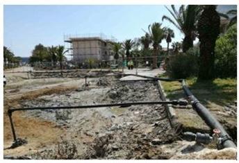
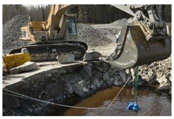
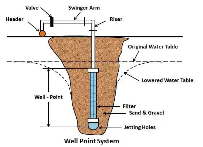
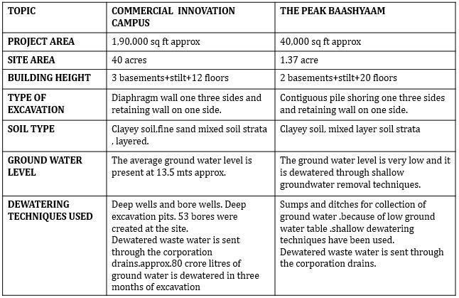
InWellpoints,submersiblepumpsareinstalledinthewell shaft and wells are drilled around the excavation area. These siphons are associated with a header pipe permitting the groundwater to be brought up by the siphons into the Well places and afterward released. One or more individual wells are drilled for deep wells, and submersible pumps are installed in each shaft. The Profound well strategy is the most ideal for profound unearthing where enormous water volumes should be released.Sumpsiphoningisthemostwell-knownstrategy for dewatering, since it fundamentally works by gravity. Thisstrategyislikewisethemostprudent.Boreholeswith submersible pumps are used in the deep well point method, which lowers the groundwater level below the excavation level. Around the excavated area, where groundwater falls due to gravity, wells with diameters of 15 to 20 centimeters are drilled. This lowers the water tableanddepletesthegroundwaterintheexcavatedarea.
5.1.4. DIAPHRAGM WALL
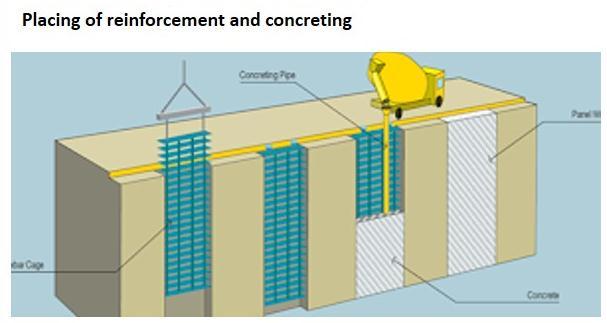
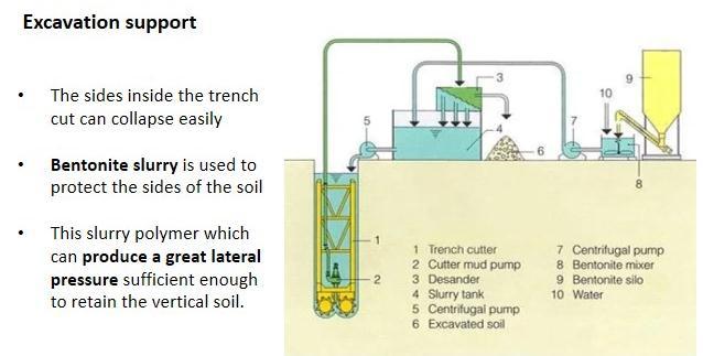
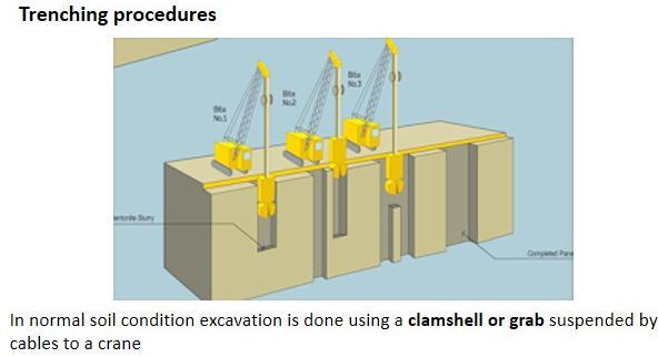
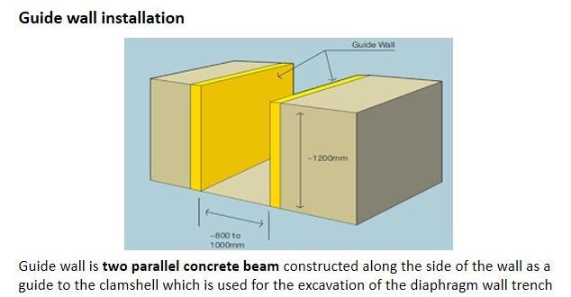
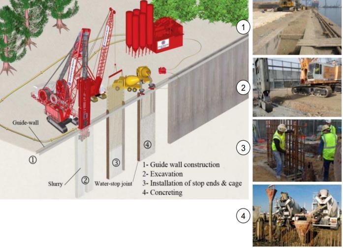
A structural concrete wall known as a diaphragm wall is builtinadeeptrenchexcavationusingeithercomponents that are cast in situ or precast concrete.Diaphragm walls are frequently used on congested sites, close to existing structures, with limited headroom, or where the depth of the excavation necessitates the removal of much larger volumes of soil in order to create stable battered slopes. Diaphragm walls are reasonable for most sub soils and their establishment produces just a limited quantity of vibration and commotion, which builds their reasonablenessforworkscompletednearexistingdesigns. Wallscanalsoincluderecessedformworkandconnections tothefloorslab.
Ground anchor bolts are used to connect the D-wall's structural and non-structural components to the concrete during diaphragm wall construction. The most common wayofprojectingtheseanchorsintothediaphragmwallis knownasSecuring.TheMooringactionstarts7daysafter the diaphragm wall boards are projected. In order to sustain force from the top, anchoring helps transfer the tension and shear forces between these structural elements and lateral support to the diaphragm wall. Boreholesof150to180mmaredrilledusingadrillrigat anglesof15to30degreesuntilthehardstrataisreached. After that, a casing pipe is used until the hard strata is reached,andthecasingpipeisinsertedintotheholeinthe middle. Endless supply of exhausting, the borehole is cleaned through compacted air. The anchor is grouted
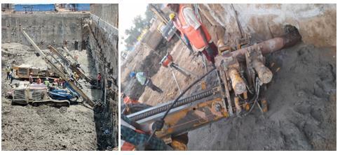

after a low relaxation pre stressed steel (LRPC) strand is insertedintothebore.Afterseventotendays,theanchor headisjackedandpre-tensioned.
5.1.7. WATER PROOFING IN BASEMENTS
A layer of watertight material known as a waterproofing membrane is applied to a PCC surface to prevent water damage or leaks. Most waterproofing membranes are sheetsthathavebeenpre-formedorappliedwithliquid.
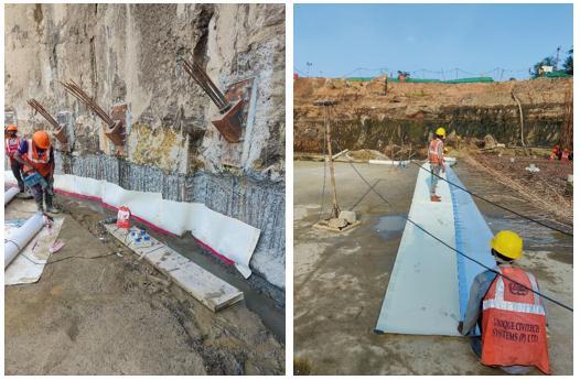
The layer is introduced around the establishments to forestall water entrance to safeguard building's cellar, waterproofing will assist with preventing water from penetrating in establishment and shield structure from water harm. The concrete is given a waterproofing membrane to help make it impossible for water to get through. A membrane HDPE film pressure-sensitive adhesive known as High Density Poly Ethylene makes it possible for poured concrete to fully bond with the membrane. It shields water and water vapour from harmful chemicals, hydrocarbons, and aggressive ground salts. It is a self-cement along one side of the roll to give fixedlapstoimproveontheapplicationcycle.
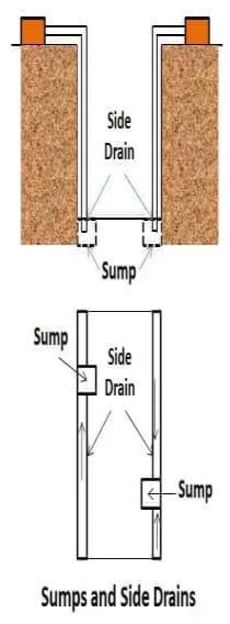
dug along the area's edge. Along the edge of the excavation, semicircular-shaped ditches or drains with a 20 cm diameter link these sumps. The water from the sides or slopes collects in sumps before being pushed away under gravity. The lowest portion of the slope may soften, ravel, or slough if there is sufficient seepage of water.Duetoupwardflow,thereisalsoachanceofpiping in the slump bottom. In these cases, the sump can be weighted down using an inverted filter made of layers of material that gets progressively coarser as it moves up fromthebottomofthesump-pit.
5.2.
5.2.1. PROJECT DESCRIPTION
A high rise residential building consisting of 2 basements+stilt+20 floors, total 240 residential units within two towers, tower 1 and 2. 2 BHK-1346 sq.ft, 3BHK-1610-1992sq.ft,4BHK-2715sq.ft.

5.2.2. DE-WATERING TECHNIQUES
Sumps and ditches dewatering method is the most basic one employed in shallow excavations in coarse-grained soils. With this technique, sumps are small pits that are
5.2.3. CONTIGUOUS PILING TECHNIQUE
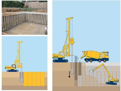
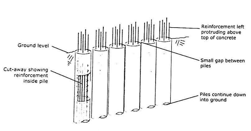
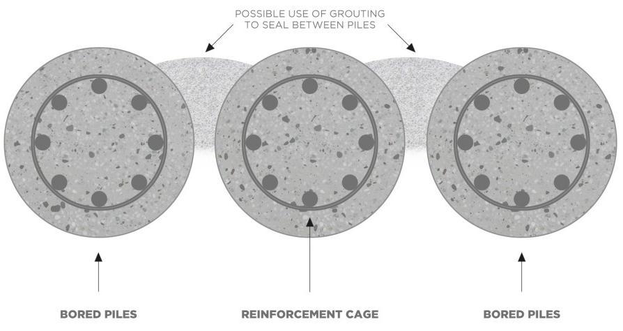
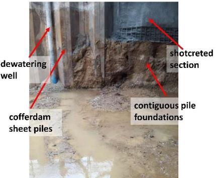
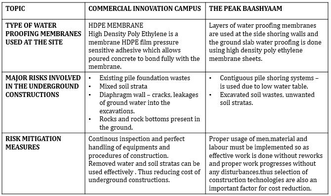
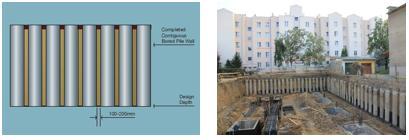
One of the most efficient and adaptable methods for building a solid foundation is piling, which is used for anything from supporting household buildings to anchoringlargetechnicalprojectslikebridgesandoilrigs. Its application doesn't stop there, though. Contiguous piling is another effective and affordable method of building a retaining wall that may be done with piles. Contiguous piling is the process of installing a series of augured pilesthat are practicallytouchingoneanother to build a retaining wall. The two most popular methods for inserting an augured pile are either drilling a hole with continuous steel sections that can later be removed and filled with concrete, or drilling a hole with a continuous steel flight that can later have grout injected into the hollow centre as it is removed. The spacing between the piles are normally between 50 and 150 mm. After filling upthesespaceswithgrout,whichhassoil packedbetween them,a second wall maybe builtinfront ofthepiles. The Tangent Pile shoring method, sometimes referred to as Contiguous Pile shoring, is a very practical shoring method.Tangentpileshoringismadeupofcloselyspaced piles, and the term originates from the way the piles are positionedrelativetooneanother.
Contiguous piling is most commonly used to build basements or cellars, where the piles can be inserted and used as a retaining wall while the basement is being excavated. In the event that ideal, they can be taken out and supplant by a strong holding wall, however it's generally more powerful to leave them set up and, as depicted, add a second wall in front. Contiguous Pile Shoringistypicallyrecommendedforareaswithclaysoils, locations where water is not as important, or locations with very little water pressure. because it can aid in the retention of dry granular materials. However, this kind of shoring will allow water to seep through the pile gap in water-bearing granular soil. Water seepage can be preventedbygroutingthepile'sgapstoformawatertight wall. Additionally, without dewatering works, contiguous pileshoringisunsuitableforahighgroundwatertable.
5.2.5. ADVANTAGES AND DISADVANTAGES OF CONTIGUOUS PILING


The fact that insertion of contiguous piling causes very little vibration is the most significant advantage. This method is ideal for use in built-up areas or close to other structures because noise and shaking are kept to a minimum because the piles are bored rather than driven. Moreover,contrastedand alternate approachesto placing in underground holding walls, adjacent heaping requires practically no additional uncovering. This makes it ideal for use in bound spaces or, once more, close to different designs. Contiguous piling has few real drawbacks, but as with any construction method, there are times when it is not the best choice. It works best in dry, firm soil, so it shouldn'tbeusedinsoilwithalotofwaterinit.
5.2.6. CONTIGUOUS PILE WALL
The execution of a contiguous pile wall requires a space betweenthepiles. Suchheapwall isessentiallyapplied in cognizant (fine-grained) materials where there is no chance of material breakdown between the heaps. The shortcretelayercanbeappliedtothepilewalltostabilize the material if necessary. Benefits to performance: Speed construction, less expensive and less difficult execution contrasted with different sorts of contiguous wall, versatilityinexecutionstage
6. INFERENCES
Reducedcostsandrisks,Riskavoidance,Newtechnologies andmethods,Improvedbackgroundcharacteristics,Better water management, Risk recognition, assessment and management, Risk communication and willingness to accept and share risks. Development of geological spatial variability framework models for predictive management of geological risks in sub soils. Increased costs are often duetoincreasedrisk.Risk=ProbabilityxConsequence(or Impact).Forimpactassessment,aframeworkisneededto assess mitigation strategies and assign responsibilities during construction and operation, along with improved quantitative assessment of risks, impacts and their likelihood of occurrence. Subterranean geological conditions should be managed primarily through the concept of subterranean zoning. This enables spatial thinking and integrated planning for the placement of surface and underground facilities in an optimized geological environment. New technologies must not only be implemented, but their short-term and long-term performance must be evaluated. Spatial and temporal variabilityofsubsurfacematerialsandconditionscontinue to pose risks, and the integration of geophysical and remote sensing methods should be reconsidered. Engineers must also consider the materials and methods used.

A good GBR (Geological Engineering Baseline Report) is carefully written to present a geological analysis of the expected conditions and/or frequency of "geological events"(temporalandspatial)expectedduringthe
project .Collected project data provides planners and contractors with information about the behavior and properties of geological materials. However, it is difficult to statistically assess the likelihood and consequences of large-scale geotechnical disruption to underground drilling, yet such phenomena are a major source of major drilling problems in underground engineering projects. We need to systematically access all surface and subsurface exposures of geological materials to obtain three-dimensional and temporal information about the spatial distribution of material properties in various formations and stress history regions. This includes field workrelatedtoroadcutsandnaturalexposures,aswellas exposuressuchasundergroundexcavationsandpits.
7. CONCLUSIONS
Engineerswillhavetoworkwithgeologists,architectsand planners on new designs for the city's underground spaces, but they will be more than just tunnels and stations.
Theseexpertsworktogethertodevelopacitythatsociety will demand in terms of excavated shape and depth, human occupation (social acceptance of underground
space, spatial reference, emergency preparedness, population aging). Be prepared for creative use of undergroundspace.Theseprofessionalsmustsupportthe development and introduction of new technologies to meettheflexibilityandqualityneedsoffacilitiesinlimited urban spatial resources. Although the focus here is on geological uncertainties and impacts, engineers are encouraged to develop and apply advanced methods for subsurface characterization, expand the use of soil amendment methods, and more. It needs to be radically rethought. Frameworks for understanding the risks and spatial variability of geological conditions and understanding of in situ stress assessment and redistribution should be improved. Improved drilling methods are also needed, including drilling/blasting, lasersandotherinnovativetechnologicalmethods.
Engineers need professional homework. Data must be collected to support rational and long-term sustainable design and his LCE, including time dependence. Furthermore, the true value of subsurface space must be determined by creating a market that can determine the value of, for example, cubic meters of subsurface space in specific soil and rock conditions. More effective management of underground and geological conditions can help foster a new understanding and public acceptanceofurbanundergrounddesign.
REFERENCES
1.[1]C.Raduetal,Numericalanalysisandmonitoringofa dual cell circular shaft adopted for a 19.5m deep excavation, (2017), pp. 1-2. [2] E. Marchidanu, Normative forthegeotechnicaldesignofthedewateringworks,lot1, writing1,Bucharest,(2011),pp.51-53.
2. (PDF) A Conceptual Socio-Hydrogeological Model Applied to Sustainable Water Management. Case Study of the Valdivia River Basin, Southwestern Ecuador (researchgate.net)
3. H. Chung, I.-M. Lee, J.-H. Jung, and J. Park, “Bayesian networks-based shield TBM risk management system: methodology development and application,” KSCE Journal ofCivilEngineering,vol.23,no.1,pp.452–465,2019.

4. (PDF) A proposed framework for hydrogeological conceptualmodelling.(researchgate.net)
5. https://www.researchgate.net/publication/330249973_E conomic_valuation_of_hydrogeological_information_when_ managing_groundwater_drawdown
6. Mixed Use Development at Heiton Buckley, Santry Avenue,Dublin9DBFLConsultingEngineersConstruction andEnvironmentalManagementPlan(CEMP).
7. (PDF) Implications of Basement Inclusion in Buildings in High-Risk Flood Zones in Yenagoa, Nigeria (researchgate.net)
8. (PDF) A BPR approach to hydrogeological risk management(researchgate.net)
9. (PDF) Assessing Ground Conditions for Flood Proof Basement Construction in Abuja, Nigeria (researchgate.net)
10. Preene, M and Brassington, F C (2003). Potential groundwaterimpactsfromcivilengineeringworks.Water and Environmental Management Journal 17, no. 1, march, 59–64.
11. [PDF] The Allocation and Documentation of HydrologicalRisk(researchgate.net)
12. [PDF] Conceptual and Numerical Model Development for Groundwater Resources Management in a RegolithFractured-BasementAquiferSystem(researchgate.net)
13. [PDF] A Framework for Risk-Based Cost-Benefit AnalysisforDecisionSupportonHydrogeologicalRisksin UndergroundConstruction(researchgate.net)
