Design and Analysis of Inboard Braking System for Vehicle

1,2,3,4Bachelor of Engineering, Mechanical Department, Datta Meghe College of Engineering, Airoli 5 Professor, Mechanical Department, Datta Meghe College of Engineering, Airoli
Abstract - An inboard braking system is a type of braking system where the brake discs are located inside the vehicle's drivetrain, rather than on the wheels themselves. This type of braking system offers several advantages over traditional outboard systems, including improved weight distribution, reduced unsprung weight, and increased packaging flexibility. This abstract provides a brief overview of the inboard braking system, its components, and its benefits. It also discusses some of the challenges associated with designing and implementing such a system, including cooling and packaging considerations and the need for sophisticated control systems to ensure safe and effective braking performance.
Key Words: InboardBraking,rotor,caliper,rotorhub.
1. INTRODUCTION
Aninboardbrakingsystemisatypeofbrakingsystemused in automobiles where the brakes are located inside the vehicle'sdrivetrainratherthanonthewheelsthemselves.In thissystem,thebrakediscsandcalipersaremountedonthe axleordifferentialhousing,ratherthanonthewheels.
Inboard braking systems are commonly used in highperformancesportscarsandracecarsbecausetheyprovide better weight distribution, improved handling, and more consistent braking performance.Bykeeping the weight of thebrakesclosertothe centreofthecar,inboardbraking systems help to reduce the car's unsprung weight and improveitshandlingandresponsiveness.
Anotheradvantageofinboardbrakingsystemsisthatthey arebetterprotectedfromtheelements,suchasrain,dust, and debris, which can cause damage to the braking components. They are also easier to cool, which helps to preventbrakefadeduringprolongedorhigh-intensityuse.
However,inboardbrakingsystemscanbemorecomplexand expensive to design and manufacture compared to traditional outboard braking systems. They also require more maintenance and are more difficult to service when comparedtoconventionalbrakesystems.
Overall,inboard brakingsystemsofferseveral advantages overoutboardbrakingsystemsintermsofperformanceand handling, but they also require more complex design and engineering, which can make them more expensive to produceandmaintain.
2.PROBLEM STATEMENT
Inboardbrakingsystemsarelocatedinsidethechassis,which reducestheunsprungweightofthewheels.Thiscanimprove the handling and stability of the vehicle, making it more responsive to driver inputs. Inboard brakes are protected fromtheelements,whichcanhelpimproveheatdissipation and reduce the risk of brake fade. This is particularly importantinhigh-performanceapplicationswherebrakingis a critical factor. By locating the brakes inside the chassis, inboardbrakingsystemsfreeupspaceontheoutsideofthe wheels.Thiscanallowfortheuseoflargertires,suspension components,andothersystemsthatcanfurtherimprovethe performanceofthevehicle.Inboardbrakingsystemscanbe designed to improve the aerodynamics of the vehicle by reducing drag and turbulence. This can improve fuel efficiencyandreducewindnoise.Inboardbrakescanbemore visuallyappealingthanoutboardbrakes,astheycanreduce clutterandvisualdistractionsontheoutsideofthewheels.
3. SCOPE AND OBJECTIVE
Improved Heat Dissipation: Inboard braking systems can be designed to dissipate heat more efficiently, reducing the risk of brake fade and ensuringconsistentperformance.
ReducedUnsprungWeight:Bylocatingthebrakes inside the chassis, inboard braking systems can reduce the unsprung weight of the wheels, improvinghandlingandstability.
Improved Aerodynamics: Inboard brakes can be designedtoreducedragandturbulence,improving theoverallaerodynamicsofthevehicle.
4.INBOARD BRAKING
"Inboardbraking"asintoatypeofbrakingsystemwhere the brakes are fitted inside the vehicle's chassis, typically nearthedifferential.Incontrast,"outboardbraking"refers to a braking system where the brakes are located on the outsideofthevehicle'swheels.
Inboard braking systems offer several advantages over outboard braking systems, including reduced unsprung weight,improvedheatdissipation,increasedspaceforother components, improved aerodynamics, and improved aesthetic appeal. However, inboard braking systems also presentcertainchallenges,suchasincreasedcomplexityand maintenance requirements, which may limit their applicationinsomesituations.
Inboard braking systems are primarily used in highperformancevehiclesandheavy-dutycommercialvehicles, where these advantages are most beneficial. They can provideimprovedhandling,stability,andsafetywhilealso enhancingtheoverallperformanceofthevehicle.
5. GEOMETRY
The geometry of inboard braking systems can vary dependingonthespecificdesignandapplication.Ingeneral, inboardbrakingsystemsaredesignedtolocatethebrakes inside the vehicle's chassis, typically near the differential. This can involve the use of special brackets or mounts to securethebrakecaliperstothechassis.
Thegeometryofthebrakecomponentsthemselves,suchas the rotors and calipers, may also be modified to optimize theirperformancewithintheinboardlocation.Forexample, the rotors may be larger in diameter to improve heat dissipation, or the calipers may be designed to fit more tightlyaroundtherotortoincreasebrakingforce
6. CONSTRUCTION
Themaincomponents oftheinboardbrakingsystem areasfollows:
1. Brake Calipers:
Inboardbrakingsystemsusespecialbrakecalipers thataremountedinsidethe vehicle'schassis.The caliperscontainthebrakepadsandareresponsible forsqueezingthemagainsttherotortosloworstop thevehicle.
2. Brake Rotors:
Inboardbrakingsystemsusebrakerotorsthatare mounted on the vehicle's differential or transmissionoutputshaft.Therotorsaretypically larger in diameter than those used in outboard
braking systems to provide improved heat dissipation.
3. Brake Lines:
Brakelinesconnectthebrakecaliperstothebrake mastercylinderorhydrauliccontrolunit,providing the hydraulic pressure necessary to activate the brakesystem.
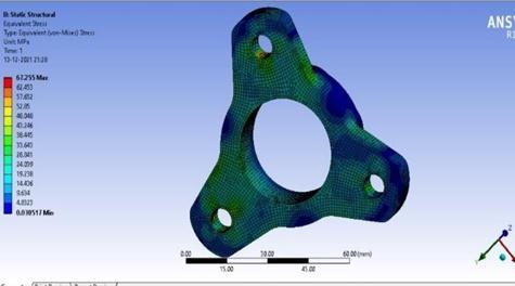
4. Rotor hub:
Special mounting brackets or mounts are used to securethebrakecaliperstothevehicle'schassisin theinboardlocation.
5. Brake Master Cylinder or Hydraulic Control Unit:
Thebrakemastercylinderorhydrauliccontrolunit isresponsibleforgeneratingthehydraulicpressure necessary to activate the brake system. In some inboard braking systems, this component may be locatedoutsidethechassis.
6. Brake Pedal:
Thebrakepedalisusedtoactuatethebrakesystem and generate the hydraulic pressure necessary to activatethebrakecalipers.
7. Brake Fluid Reservoir:
Thebrakefluidreservoirstoresthebrakefluidused to generate the hydraulic pressure necessary to activatethebrakesystem
Overall,thecomponentsofaninboardbrakingsystemwork together to provide effective and efficient braking performance,whileminimizingtheweightandcomplexityof thebrakingsystem.Thespecificcomponentsanddesignofan inboard braking system can vary depending on the application,thetypeofvehicle,andotherfactors.
7. WORKING
Theworkingofaninboardbrakingsystemissimilarto thatofaconventionalbrakingsystem,withtheprimary differencebeingthelocationofthebrakecomponents. Herearethegeneralstepsinvolvedintheworkingofan inboardbrakingsystem:
1. When the driver presses the brake pedal, it activatesthebrakemastercylinder,whichcreates pressureinthebrakelines.
2. Thebrakefluidflowsthroughthebrakelinesto the brake calipers, which are located inside the vehicle'schassisnearthedifferential.
3. The brake calipers hold the brake pads and use thepressurefromthebrakefluidtoclampthepads ontothebrakerotors,creatingfrictionandslowing orstoppingthevehicle
4. Asthebrakepadscreatefrictionagainsttherotor, heat is generated. In some inboard braking systems, cooling ducts or other features may be usedtodissipatetheheatandpreventbrakefade.
5. Oncethebrakepedalisreleased,thepressurein thebrakelinesisreleased,andthebrakecalipers releasethebrakepadsfromtherotor,allowingthe vehicletomovefreelyagain.
Overall, the working of an inboard braking system is designed to provide reliable and effective braking performance, while also minimizing the weight and complexityofthebrakingsystem
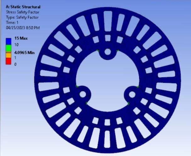
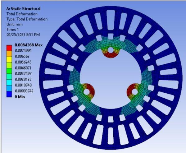
8. CALCULATION
Calculation for braking torque
Mass=270kg
Deceleration=0.8g=0.8X9.8=7.84
Heightofcentreofgravityofvehicle=21inch=0.533m
WheelBase=56inch=1.4224m
WeightRatio=x=0.4(40:60)
TyreRadius=0.2667m
PedalRatio=7:1
Dynamic Load Transfer (DLT)
= =794.01N
Load on Front Axle:
=(WeightofvehicleXx)+DLT
=(mgXx)+DLT
=(270X9.81X0.4)+794.01
=1853.49N
Load on Rear Axle :
=(WeightofvehicleX(1-x)0-DLT
=(mgX(1-0.4))–DLT
=(270X9.81X0.6)-794.01
=795.21N
Wheel Torque on each wheel
1. Front: =0.7X1853.49X0.2667X0.5 =173.01Nm
2. Rear: =0.7X795.21X0.2667X0.5 =74.22Nm
Calculation for Pressure generated by Master Cylinder
1. Pressureinbrakeline= = = =7367827.56N/m =7.36MPa
2. PressureX( )X(no.ofpiston) =7367827.56X( )X2 =10416.02N
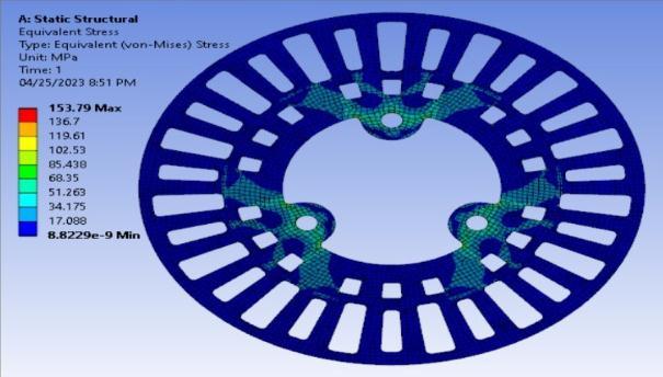
Calculation for braking torque
ClampingforceX × =10416.02X0.3X0.0715 =223.42Nm
Braking torque > Wheel Torque
223.42 Nm> 173.01 Nm
Thereforevehiclewillcomeatrest.
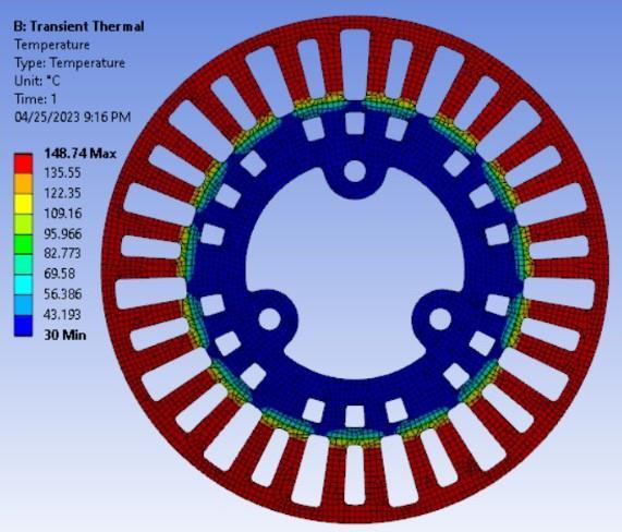
Thermal Calculation:
Kinetic Energy for Vehicle:
m=MassofVehicle
v=velocityinm/s
m=270,v=60km/hr,x=0.6(StaticFactor)
=22509J
Stopping Time for Vehicle:
v=u+at
v=finalvelocity,u=initialvelocity,a=acceleration,t=time
0=16.67+(-0.8X9.81)Xt
T=
T=2.125
Braking Power:
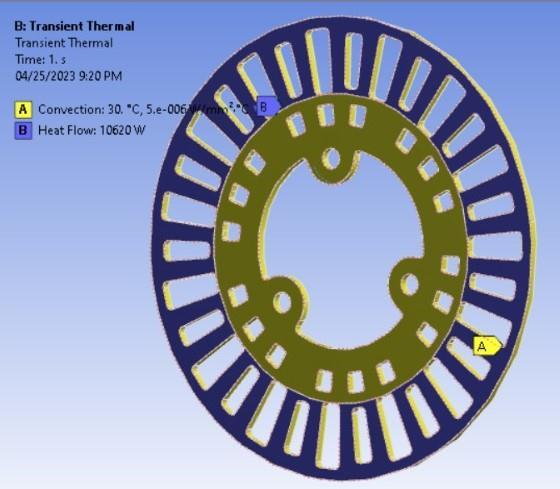
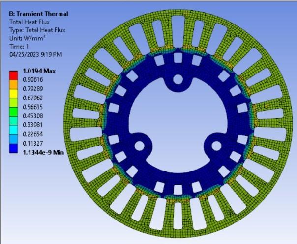
Heat Flux:
Q=
A=Areasweptbypads
Q= Q=653623.05W/
Calculatedheat fluxis approximatelyequal to the derived heatfluxfromAnsysworkbench(TransientThermal)


11. CONCLUSION
Aninboardbrakingsystemisabrakingsystemthatislocated insidethevehicle'swheelhub.Itisapopularchoiceforhighperformance vehicles due to its ability to provide better balance and weight distribution. In addition, the inboard brakingsystemismoreaerodynamicallyefficient,resultingin improvedfueleconomyandreducedemissions.
The inboard braking system has several advantages over traditional braking systems. One of the most significant advantagesisthatitprovidesbetterstabilityandcontrolover thevehicle,especiallyduringhigh-speeddrivingorsudden stops.Italsoprovidesamoreconsistentandreliablebraking performance, which is critical in racing and other highperformanceapplications.
Inconclusion,theinboardbrakingsystemisasuitableoption for high-performance vehicles or racing cars, where the benefits of improved handling and braking outweigh the addedcostsandcomplexity.Foreverydayvehicles,amore traditionaloutboardbrakingsystemmaybeamorepractical and cost-effective choice. Ultimately, the choice of braking systemdependsonthespecificneedsandrequirementsof thevehicleanditsintendeduse.
12. REFERENCES
Here are a few references on the inboard braking system thatyoumayfindhelpful:
1. "InboardBrakes:IsThistheFuture?"byAaronGold, published on Autotrader (https://www.autotrader.com/car-news/inboardbrakes-future-281474979841706)
2. "InboardBrakes"byRacecarEngineering,published on Racecar Engineering (https://www.racecarengineering.com/articles/inboard-brakes/)
3. "Inboard Brakes: An Overview" by Paul Haney, published on Sports Car Club of America (https://www.scca.com/articles/2011533-inboardbrakes-an-overview)
4. "Inboard Brake System Design and Analysis for FormulaSAERacecar"byRohitV.Patel,published onInternationalJournalofScientific&Engineering Research (https://www.ijser.org/researchpaper/InboardBrake-System-Design-and-Analysis-for-FormulaSAE-Racecar.pdf)
5. "The Design and Implementation of an Inboard Brake System for a Formula SAE Racecar" by TimothyA.Morgan,publishedontheUniversityof Michigan Digital Library (https://deepblue.lib.umich.edu/bitstream/handle/
2027.42/86169/tmorg.pdf?sequence=1&isAllowed =y)
6. Muscolo, G.G. (2014). Inboard Brake System for Motorcycles. SAE International Journal of CommercialVehicles,7(1),207-214.
7. Li, Y., Sun, Z., & Liu, S. (2018). The Research and DevelopmentofInboardDiscBrakeSystemBased onFiniteElementAnalysis.AdvancesinMechanical Engineering,10(4),1-12.
8. Hojo, M., Kishida, K., Nakahira, M., & Okabe, K. (2015).DevelopmentofanInboardVentilatedDisc Brake System for a High-Performance Sports Car. SAE International Journal of Passenger CarsMechanicalSystems,8(1),97-102.
9. Zhang, S., Li, G., Li, H., & Li, S. (2019). Design and Analysis of an Inboard Disk Brake System for a Hybrid Electric Vehicle. Journal of Mechanical EngineeringandSciences,13(2),4922-4936.
10. Yousif, S.A., Abdulateef, J.A., & Aziz, A.A. (2020). AnalysisofThermalPerformanceforInboardDisc BrakeSysteminHeavyVehicleUsingANSYSFluent. InternationalJournalofAutomotiveandMechanical Engineering,17(2),7888-7900.
Theseresourcesprovideinsightsintothetechnologybehind inboard braking systems, their advantages and disadvantages, as well as their applications in various industries,particularlyinmotorsports
13.BIOGRAPHIES
Swapnil Popat Bhosale
BachelorofEngineering ,Student ofMechanicalDepartment,inDatta Meghe College of Engineering, Airoli,NaviMumbai.
Yash Ramesh Kadam
BachelorofEngineering ,Student ofMechanicalDepartment,inDatta Meghe College of Engineering, Airoli,NaviMumbai.
Vedant Tushar Musale
BachelorofEngineering ,Student ofMechanicalDepartment,inDatta Meghe College of Engineering, Airoli,NaviMumbai.
Ravi Kisan Yadav
BachelorofEngineering ,Student ofMechanicalDepartment,inDatta Meghe College of Engineering, Airoli,NaviMumbai.


Prof. Nilesh Limbraj Shinde
Professor in Mechanical Department of Datta Meghe CollegeofEngineering,Airoli,Navi Mumbai.