Differential Current Protection of Transformer using Arduino
Aamir Hussain sheir 1, a), Yasir Mohd Dar 1,b), Harvinder Singh2Chandigarh University, Gharuan, Mohali (Punjab), India 140413
1ME, Department of Electrical engineering (Electric Vehicle)
2Professor, Department of Electrical Engineering, Chandigarh University, Gharuan, Mohali (Punjab), India 140413

Abstract: The Protection of the electric power network system is very important and essential for a dependable electrical power supply. Protection should be very fast and efficient as Electrical power systems experience faults for various reasons. These faults must be foreseen and safety precautions applied to the power system. Transformers, the heart of the power system save the world from darkness are to be protected is very essential. Transformers are the important parts ofthe powersystem. In this paper, we will use a differential relay mechanism with Arduino. By programming the Arduino, the protection of transformers is to be done. Programming is quite more efficient than the differential relay mechanism, so it is better to use Arduino instead of a differential relay. The working of the transformer is sensed & verified by Arduino every second. If Arduino finds any error i.e in an increase of current, temperature, and any abnormal function, then it sends a command to the circuit breaker to trip the main transformer. So, it is the efficient and best method to protect the transformers under abnormal conditions.
Introduction:
Themainimportantpartofthepowersystemnetworkis the transformer as they do stepping up voltage and stepping down the voltage. The stepping of voltage is done at the power generating station and then power is transmitted at high voltage to reduce transmission loss. Transformers are used in a wide variety of applications, from small distribution transformers serving one or moreuserstoverylargeunitsthatareanintegralpartof thebulk powersystem.Inthedesignofelectrical power transmission and distribution systems, various factors needtobeconsideredinthequesttosatisfytheneedsof electricity consumers. Electrical power systems experience faults at various times due to various reasons. These faults must be foreseen and safety precautions applied to the power system. Power system protectionis essential for a dependable electrical power supply. Also, transformers are a critical and expensive component of the power system. The power systems engineer must include in his design, safety measures to avert any destructive occurrences that the system may undergo at any given time. Transformers are a critical andexpensivecomponentofthepowersystem.Theyare
considered the heart of the power system. Due to the long repair of and replacement of transformers, a major goal of transformer protection is limiting the damage to the faulted transformer. Protection against fault in the power system is essential for reliable performance. A power system is said to be faulty when an undesirable condition occurs in that power system, where the undesirable condition may be a short circuit, overcurrent,over-voltage,etc.Fordecades,fuses,circuit breakers,andelectromechanicalrelayswereusedforthe protection of power systems. The traditional protective fuses and electrometrical relays present several drawbacks.Therearevariouswaysareemployedforthe protection of transformer like over current, differential, etc.Eachisemployedforadifferentpurpose.Thetypeof protection for the transformers varies depending on the application and the importance of the transformer. Transformersareprotectedprimarilyagainstexternalas well as internal fault and overload. The type of protection scheme used should minimize the time for clearing fault and must discriminate between fault conditions and overload conditions. Here for internal fault differential protection scheme is used. Here in this scheme, we used Arduino with a voice announcement circuit and mechanical relay. Hereby using Arduino instead of a conventional relay gives many advantages like fast fault detection and clearing as well as cost reduction as in comparison with electromechanical and solid-state relays, Arduino based relay performs realtime computation which leads to enhancement in relay performance, facilitating faster, more secure protection forpowertransformer.
Differential protection
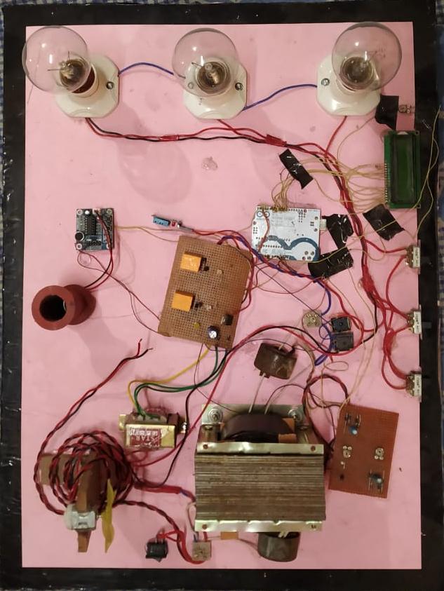
Differential current protection is the most reliable & populartechniqueinpowersystemprotection,workson the basic theory of Kirchhoff’s current law. Fig.1 Differential relay mechanism with arduino as a main controller. This protection requires a set of current transformers & each compares the currents and calculatesthedifferencebetweenthetwo.Undernormal operatingconditions,currentsinprimaryandsecondary are the same. So, the proportionate voltages generated by the CTs on primary and secondary are the same. Wheneveraninternalfaultoccursinthetransformerthe
currents sensed by the CT on primary and secondary differs by some amount. As a result, the voltage sensed bytheArduinofromprimaryandsecondarydiffers.
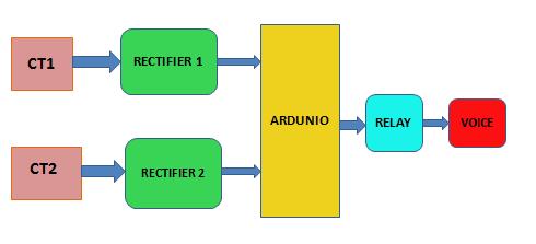
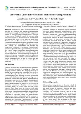
As seen in the circuit diagram figure 2 there are many componentsconnectedtoperformproperly.Theinputis fedtotheprimaryoftheisolationtransformerusedhere instead of the power transformer. Two current transformers are used to sense the input current. Input is given to the transformer through the current transformer placed at the input terminal (CT-1).CT-1 senses the magnitude A.C fed to the primary isolation transformer and the current is then supplied to the rectifier to convert it into corresponding D.C and then D.CissenttotheArduinoboard.Aftertheinputisfedto the transformer, the isolation transformer induces the samevoltageinthesecondaryofthetransformerthenit passesthroughthecurrenttransformerconnectedtothe secondary side of the transformer (CT-2). CT-2 senses thecurrentinthesecondaryoftheisolationtransformer andpassesittorectifiercircuit2whichconvertsittothe correspondingD.ClevelwhichisfedtoArduino.Arduino aftergettingtwoinputsignals fromtworectifiercircuits for comparison. Arduino compares the two signals to find any difference between the input signals and if the difference is greater than pre-set value then Arduino sends a signal to the relay to shut the circuit. Arduino andvoicecircuit workson 5-20vD.C supply. Toget the D.C supply of 5-20 v a stepdown transformer is used in the circuit (220/12). The output of the stepdown transformer isthen fed to therectifiercircuit to convert itto12VD.Cwhichisgiven toArduinoand voice circuit fortheirworking.Theloads areconnectedacross 230 V A.Csupplydirectly on the secondaryof thetransformer.
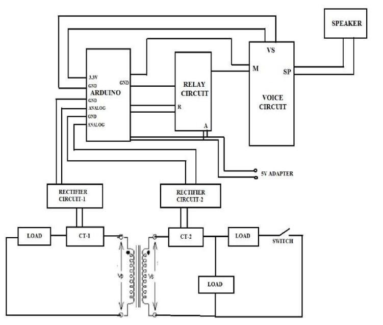
Eachloadisprovidedwith a separateswitchtooperate. AVoice circuit isprovided togiveanalertat thecertain differences in the primary and secondary current through a speaker. Relays control the loads and voice circuit. Arduino is the main component in this circuit. It is a single-board microcontroller programmed by using Arduino programming language (java). Arduino is used to comparing the currents on both primary and secondary. Two rectifier circuits are used in this circuit to convert the AC voltage into DC voltage for the use of Arduino. Current transformers also provided one on primaryandanotheronsecondarytotapthecurrentson both sides and to give proportionate voltage to the rectifier circuit. The output of the Arduino is connected to the relay. The relay here is a 12V DC 1-phase relay. Under normal operating conditions currents on primary and secondary are the same. So, the proportionate voltages generated by the current transformers on primaryandsecondaryarethesame.Thesetwovoltages are given to the Arduino. The proportionate voltages generated by current transformers are rectified by the rectifiers in the circuit. These two voltages will be the same in magnitude and the difference is zero. So, the Arduinogivesnosignaltotherelay.Wheneverextraload or an internal fault occurs in the transformer the currents sensed by the CT on primary and secondary differs by some amount. As a result, the voltage sensed by the Arduino from primary and secondary differs. As thereisadifferenceinthevoltagesensedbytheArduino i.e., the difference is not zero. Arduino, give a signal to therelayaccordingtoapredefinedprogram.Therelayis activated by the Arduino microcontroller the relay then activates the voice announcement circuit. The voice circuitwillgivetheoutputapredefined voiceasanalert to the operator. After three consecutive voice alerts Arduino will give a trip signal to the relay board. The Relay board is connected in series with the supply will open its contacts thus the supply to the hardware setup willbedisconnected.
Software for program an Arduino
AlgorithmNSoftwareimplementation
#include"DHT.h"
#include<LiquidCrystal.h>
LiquidCrystallcd(6,7,8,9,10,11);
intanalogInput=0;
floatvout=0.0;
floatvin=0.0;
floatR1=100000.0;//resistanceofR1(100K)-seetext!
floatR2=10000.0;//resistanceofR2(10K)-seetext!
intvalue=0;
intk=0; intl=0;
#defineDHTPIN2 //whatdigitalpinwe'reconnected to
//Uncommentwhatevertypeyou'reusing!
#defineDHTTYPEDHT11 //DHT11
DHTdht(DHTPIN,DHTTYPE);
inttt;
intrelay1=3; intrelay2=4;
voidsetup(){ pinMode(analogInput,INPUT);
lcd.begin(16,2);
pinMode(relay1,OUTPUT); pinMode(relay2,OUTPUT); Serial.begin(9600); Serial.println("DHTxxtest!");
dht.begin(); }
voidloop(){ //Waitafewsecondsbetweenmeasurements. ttt(); delay(100);
vol(); if(tt<34) { if(l==0) { lcd.setCursor(0,0);
lcd.print("Temp="); lcd.print(tt);
lcd.print(" "); digitalWrite(relay2,LOW); } } elseif(tt>34)
{ l=1; if(l==1)
{ lcd.setCursor(0,0);
lcd.print("Temp=");
lcd.print("Max "); digitalWrite(relay2,HIGH); } } } voidttt()
{ delay(500);
// Reading temperature or humidity takes about 250 milliseconds!
RESULTS AND DISCUSSION
Themathematicalcalculations whicharerequiredatthe various stages and the components used these rating have been mentioned below . The results focuses upon the tripping of the relay after the pre-determined limit and time taken for the same and the voice alert by the arduinobeforethefinaltripping.
Calculation
Voltagerating=230V
Whenswitch1isclosed,normalload=29mA
When switch 2 is closed for alarm, load required for voicecircuit≈64mA
Timerequiredbyvoicecircuittorespond≈2seconds
When switch 3 is closed for overload, load required for tripping the relay to disconnect the supply to circuit ≈90mA
Timerequiredtocutoffload≈2seconds
TemperatureandhumiditysensorDTH11sensor
Temperature of transformer required for operating the fan=35 oC
Component Rating
1. MainTransformer=1:1.
2. Turnsratio=2.7turns/volt.
3. Stepdowntransformer=12V/1A.
4. Bridgerectifiers=2(usedforconversionofactodc).
5. Rectifiersareadjustedusingpotentialdivider
6. Diode=1A/50V.
7. 4ON-OFFswitches.
8. Relays=312V/180Ωelectromagneticrelays
9. DTH11 heatandhumiditysensor.
10. Microcontrollerboard 328
11. 7805voltageregulatorIC
12. Npntransistorforrelayoperation
CONCLUSION, LIMITATIONS AND FUTURE
Applications
UnbalanceCausedbytheLoadCurrent
FaultsonLVSideoftheTappedTransformers
MagnetizingInrushCurrents
ExternalFaultsonHVSystem
Advantages.
ReadytoUse
Arduinois readytousestructure.AsArduinocomesin a complete package form which includes the 5v regulator, a burner, an oscillator, a micro-controller, serialcommunicationinterface,LEDandheadersforthe connections. A programming port is their on Arduino
board Just plug it into USB port of your computer and that'sit.
Effortless functions
Some functions that make life incredibly simple can be seenwhileprogramminganArduino.Theautomaticunit conversion feature of Arduino is another benefit. You could say that you don't have to bother about unit conversionswhiledebugging.Justfocusallofyoureffort onyourprojects'corecomponents.Therearenoadverse effectstobeconcernedabout.
Large community
On the internet, there are numerous forums where people discuss the Arduino. Arduino is widely used by professionals, enthusiasts, and engineers to create their creations. You can simply find assistance with anything. Additionally, every single function of Arduino is explainedontheofficialArduinowebsite.
Easy to use
My belief is that if you began using micro-controllers with Arduino, it will be quite challenging for you to create sophisticated intelligent circuits in the future. A person cannot understand the fundamentals of many things, including as serial communication, ADC, and I2C, because of the simplicity of the Arduino hardware and software.
Therefore, we should sum up the benefit of Arduino by noting that while working on various projects, all you need to worry about is your creative concept. The rest willbehandledbyArduno.
Limitations and Future recommendations
Transformer protection is a very crucial engineering principle. It is clear that the demand for electricity is increasingfastwithincreasingpopulationandeconomic growth. This demands that more sophisticated transformerprotectionmethodsbeusedinthefuturein ordertomaintainastableelectricalpowersupplyaswill bedemandedbythegrowingeconomy.
Based on the work done in this project, the future may demandthatsomeimprovementsbemade.
Some of the limitations faced in the design and future solutionsinclude;
a) The current sensor does not offer a 100% sensing speed as needs some time do sense and transfer the signal to the microcontroller. A device with a faster sensingspeedshouldbeestablished.
b)Insteadofusingtherelayasaswitch,asemiconductor switchingdevicesuchasathyristorshouldbeused.
c) Another limitation is that whereas the relay automatically recloses its contacts, the contactor used has to be restarted physically by an operator. Using a circuitthatautomaticallyreclosesthesystemwouldbea greatsolution.
d) Lastly, the method of relaying the information to an operator in a control room far from the sub-station has not been explored in this project due to time constraint. An area for future study is how the system can automatically send a message to a control centre and notify the engineers of the exact location of a faulted transformer.AGSMmodulecanbeusedinthiscase.
Conclusion
The main objective if this research paper has been to design and implement a system that uses an Arduino to protect a power transformer. This objective was achieved as the system works effectively. As the current circulating in the transformer coil varies, the LCD displays the readings. The relay is able to operate and isolate the transformer in case of an over current fault. The relay is the main switching element in the system. When energized, it opens its contacts and de-energizes the contactor thus isolating the transformer to safety in caseofadversecurrentconditions.Theotherperipheral devices act as means of sending warning messages in case a fault occurs. This system if put to use in power transformer protection can serve the purpose with greateradvantagesthantheanalogueovercurrentrelay. Its ability to automatically reclose the circuit after the fault is cleared warrants the system usability in remote areasthatmaybetoofarforanoperatortoreacheasily and reconnect the transformer back to the supply line. Theadmirablefactaboutitistheaccuracywithwhichit closes and recloses during either normal operation or faultoccurrence. Everycustomerdesirestooptimizethe usage of a gadget yet at a low cost. The cost of implementing the system is relatively cheap as the components used are few and can be cheaply found in the market. The Arduino can be used to drive multiple relaysusingthesameprogram.Theonlythingthatneeds to be done is free more ports for multiple input and outputs.Thiswillallowformorevariablesfromdifferent transformersandmultipleoutputstodifferentrelays.
Owing to the fact that transformers are very important components of the electrical power system, their safety is paramount. Over current phenomenon can cause damage to transformers. Damage to a transformer puts interrupts electrical supply to consumers. Blackouts cause economic derailment and disorients consumers’
work schedule. This explains why this system is needed andcanhelpmitigatetheeffectsoffaultinatransformer.
Incaseanovercurrentfaultoccurs,thepowerengineers should consider taking time to evaluate the possible cause of this phenomenon. For example, if there is an overload at the consumer end, there may be a call to install a new transformer that can withstand the increased load. The other mitigation option may be to add another supply line to the consumer so that the consumerdemandismet.
This system comes with a power supply that can be directlypluggedto240Vsourceandgivetheappropriate operating voltage. The 240V source can be easily cultivated in a power system line. It can be used in substationsorindistributiontransformers.
REFERENCES
[1]. XU Yan, WANG Zeng-ping,“Research on novel Transformer Protection based on the Characteristics of VoltageandDifferentialcurrent’’,IJRAT pp
[2]. K. Inagaki, M. Higaki, Y. Matsui, "Digital ProtectionMethodforPowerTransformers Basedonan Equivalent Circuit Composed of Inverse Inductance", IEEE Transactions on Power Delivery,Vol.3, October 1988pp
[3]. AkshayR.Thakare1,“ProtectionandMonitoring Of Transformer Using Arduino”,Electrical Department, Savitriba PhulePuneUniversitypp
[4]. M.N. Sandhya Rani,“Differential Current ProtectionofTransformer”,DepartmentofElectricaland Electronics Engineering GRIET, Hyderabad, Andhra Pradesh,India.pp
[5]. Generating-transmitting-and-distributingelectricity.[Online]
http://technology.ezinemark.com/generatingtransmitting-and-distributingelectricity7d30ca53b6b0.html
[6]. Allaboutcircuits.[Online] http://www.allaboutcircuits.com
[7] Current protection schemes www.google.com/current-protection-images-cc
[8]. Arduino – Home Page from http://www.Arduino.cc
[8]. International Journal for Research in Applied Science & Engineering Technology (IJRASET) ISSN: 2321-9653; IC Value: 45.98; SJ Impact Factor: 6.887
Volume 6 Issue II, February2018- Available at www.ijraset.com
[9]. Prof. R.B.Pandhare1, Parmanand Waghmare2, Ashwini Gavande3, Gopal Bahekar4 “Transformer ProtectionbyUsingArduinowithGSMModem”students of Electrical engg. Special issue National Conference “CONVERGENCE2017”,9thApril2017(IJRAT).
[10]. Automatic Method Of Protecting Transformer UsingPicMicrocontrollerAsAnAlternativeToTheFuse Protection Technique A. Z. Loko1, A. I. Bugaje2, A. A. Bature3
[11]. Karpe S R1, Sandeep Shelar2, Shraddha Garkad3,ShrutiLakade4“FaultDetectionandProtection of Transformer by Using Microcontroller”, International JournalofModernTrendsinEngineeringandResearch.
[12]. Atthapol Ngaopitakkul and Anantawak kunakorn, ‘Internal Fault Classification in Transformer Windings using Combination of Discrete Wavelet Transforms and Backpropagation Neural Networks’ Internationaljournalofcontrol,automationandsystems.
[13]. Mazouz A.Salahar Abdallah R. Alzyoud, ‘Modelling of transformer differential protection using programmable logic controllers’ European journal of scientificresearch.
[14]. https://www.researchgate.net
[15]. International Journal Of Electrical, Electronics And Data Communication, ISSN: 2320-2084 Volume-5, Issue-1,Jan.-2017
http://iraj.in
[16]. Vadirajacharya. K, Ashish Kharche, Harish Kulakarni,VivekLandage“TransformerHealthCondition Monitoring Through GSM Technology”, International Journal of Scientific & Engineering Research Volume 3, Issue12,December-2012
[17].
https://www.engineersgarage.com/articles/gs m-gprs-modules
[18].
https://www.engineersgarage.com/contributio n/high-quality-voice-recorder-using-ic-apr33a
[19]. http://forum.Arduino.cc/index.phptopic=206878.
[20]. Ishant Sharma, Tarak Patel, Prof.Dhaval Tailor “Differential Protection of Transformer Using Arduino” International Journal of Innovative and Emerging ResearchinEngineeringVolume3,Issue7,2016
[21]. Using Arduino with Voice Alert” International Journal of Innovations in Engineering and Technology, Volume6Issue
BIOGRAPHIES
YasirMohdDar

M.E Scholar at chandigarh University department of electricalengineering
AamirHussainSheir M.E Scholar at chandigarh University department of electricalengineering