A COMPREHENSIVE REVIEW OF DC MICROGRID PROTECTION TECHNIQUES
Abstract - Due to the possible usage of photovoltaic (PV), wind, and battery-based energy sources, microgrids have become popular in industry and research. Both academic institutions and private businesses have paid a considerable amount of attention to DC microgrids during the last decade. In terms of dependability, control simplicity, integration of renewable energy sources,efficiency and connectivity of dc loads, DC microgrids have shown themselves to be superior than AC microgrids. In spite of these many benefits, developing and deploying a suitable protection system for DC microgrids continues to be a considerable issue. Even though there aren't any usual zero crossings, the issue is brought on by the sudden spike in dc fault current that needs to be put out. If this isn't done, prolonged arcs might result. In this article, the difficulties associated with DC microgrid protection are studied from a variety of perspectives. These viewpoints cover the features of dc fault currents, ground systems, fault detection methods, protective device approaches, and fault localization methods. An in-depth analysis has been performed on each individual section of this report. In conclusion, a short discussion is provided on emerging tendenciesinthefieldofDCmicrogridprotection.
KEYWORDS : DCMicrogridProtection,Renewableenergy sources, DCconverter,DCFaults,Grounding.

I. INTRODUCTION:
Thereisa growingbodyofevidenceindicatingthatdirect current (DC) systems are superior than rival alternating current (AC) systems in terms of efficiency, complexity, power transfer ratio, and overall cost [1, 2]. The majority of loads, including electric vehicles (EVs) and lightemitting diode (LED) lights, are made to operate on DC power, and many Distributed Energy Resource (DER) systems, including photovoltaic (PV), fuel cells, and battery energy storage, also operate on DC power. As a result,DCsystemsmakethemostsenseatthepointofuse. DCsystemsalsomakeeconomicsense.
The power quality implications that DC systems haveonpublicutilitynetworksisanotheranotherbenefit of using DC systems. Because such systems, Will only connect through a single point of interface, if there is any AC interface at all [1,] the management of reactive power flow and frequency control may be accomplished at a
lower cost and with a reduced risk.The use of multiterminal High Voltage DC (HVDC) distribution systems to incorporate renewable energy sources into electrical utility grids in Europe and China [3], [4], the application of mobile transportation systems with integrated power and energy management to ships, aircraft, and vehicles [5], [6], and the electrification of remoteareasthroughlocalDCmicrogridsthatincorporate solar energy and battery energy storage into community and home electrification. [3] [4] Distributed energy resources (DERs) and local loads can be easily incorporated into mobile transportation systems with integratedpowerandDCmicrogridsthathaveatleastone point of interface to the AC electrical grid using a bidirectional AC - to - DC converter. A smart grid is another name for this kind of microgrid.All of the instances shown above might be classified either as a DC microgridinthetraditionalsense(onethatisconnectedto the grid) or as an islanded DC microgrid (i.e., for transportation systems).The design of an adequate protection system for DC microgrids has been and continuestobeaconsiderableissueoverthelast10years, despite the various benefits that come with doing so. The difficulty is caused by dc fault current's features, which includetheabsenceofazerocrossingpointthatnaturally arises and the ability to abruptly surge to more than a hundred times the nominal current during sudden fault initiation [9], [10]. (which is the main mechanism that AC electromechanicalcircuitbreakersrelyontoputanendto arcs and finally isolate faults.) An suitable grounding design, a fault detection strategy that is quick and effective, a fault current limiting mechanism, and an appropriateDCcircuitbreakerarerequiredtogetaround the challenges that come with DC microgrid protection. Grid reliability, leakage current reduction, ground fault detection,andthesafetyofworkersandequipmentduring fault conditions are all impacted by grounding in DC microgrids.. A safe, fault ride-through, and easy-to-detect grounding system must be presented [11]. To avoid equipmentdamage,thefaultmustbediagnosedandfound quickly and accurately due to DC fault current characteristics. The rapid shift of unexpected dc fault current initiation makes protective relay coordination problematic [10], [12].There are five fault detection techniques that have been presented: directed overcurrent, overcurrent, current derivative,distancebased and differential. DC microgrids have lower line
resistance and reactance than AC systems, making fault location techniques, including passive and active approaches, significantly more difficult. A defect detection/location technique must balance cost, computing load, simplicity, and performance. A suitable DC circuit breaker (DCCB) isolates the problem and returns the DC microgrid to safe functioning. The issue is completely air-gapped or galvanically isolated from the system. For dc fault current characteristics, DCCBs must have a quick response time,high reliability, galvanic isolation, low cost, low conduction loss and extended lifespan[9],[13].DCCBsmustbebuilttomeetexpectations orselectedfromdevicesthatarealreadyonthemarket.
This paper defines fault as a short-circuit from, across two lines, any line to ground, or as two lines to ground anyplace in the system. Any practical fault protection strategy must handle the sudden-inception short-circuit problem to reduce equipment damage. Section2analysesDCfaultcurrenttoemphasisetheneed of quick fault identification, localization, and isolation. Section3comparesdcmicrogridgroundingsolutionsfor
straycurrent,faultdetection,commonmodevoltage, and ride through. Section 4 reviews overcurrent, directed overcurrent, current derivative, differential, and distance fault detection techniques. Discussing each protection method's pros and cons. Section 5 compares fuses, mechanical DCCB, solid-state DCCB, hybrid DCCB, and Zsource DCCB for cost, reaction time, and losses. Finally,
Section 6 discusses local measurement, Traveling Wave (TW), injection-based fault finding techniques and differential.
II. DC FAULT ANALYSIS:
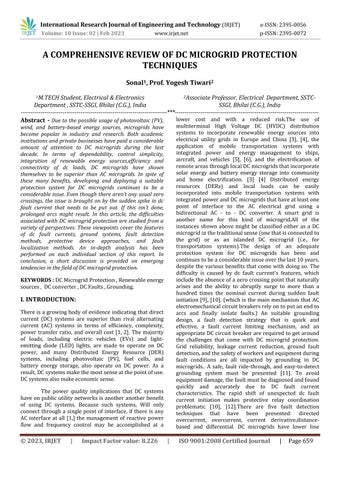
Numerous topological topologies, including zonal , multiterminal and DC looping, are used to group DC microgrids.The application, degree of dependability, and voltage level are the three primary considerations that shouldguideone'sselectionaboutthearchitectureofaDC microgrid[14].Forinstance,theUnitedStatesNavyplaces a strong emphasis on the development of zonal DC microgrids in order to establish a shipboard system with high power density, high survivability, and low implementation cost [15]. Two different types of DC bus architectures exist, regardless of the various topological configurations that can be found in DC microgrids (Fig.1). ThesearetheunipolarDCbus topology,whichmakesuse of two-level Voltage Source Converters (VSCs), and the bipolar bus topology, which makes use of three-level neutral-pointclampedVSCs.TheunipolarDCbustopology hasseveralbenefits,butthebipolarDCbustopologyoffers some advantages that are more advantageous than the unipolar DC bus architecture. These advantages include better reliability, larger power capacity, and flexibility in theconnectionsbetweenloadsandDGs[16].
The use of two-cascaded rectifiers on the DC side is one of the topologies that makes the construction of a bipolar DC microgrid one of the simplest. A transformer withtwinsecondarywindingsisnecessarysincetheseries connection has the potential to cause a DC voltage offset. This may be avoided by using a transformer with this feature. This might result in an increase in both size and expense. Other one-converter based topologies, like VSC with a neutral line connected to DC mid-point and NPC converter, have addressed this issue. When a neutral line is linked to the DC midway, the transformer may become saturatedinaVSCduetotheDCcomponentofthecurrent [17].However, there is no guarantee that the DC voltage will be balanced under any of the potential operating conditions for the NPC converter due to an inherent problem with voltage balancing [18].The DC bus voltage has to be stabilised by a voltage balancer that has been thoughtfullydevelopedinordertoaddresstheproblemof voltage imbalance that occurs in any of these two setups. Regardless of the DC microgrid's configuration, the DC failure could occur in the DC bus or the DC cables that connectthevarious microgridcomponents.Asingle point ofenergy interface between distributedgenerators(DGs), energystoragesystems(ESSs),andloadsiswhataDCbus and DC interconnections are intended to do.This is because the purpose of a DC microgrid is to make the microgridassimpleaspossible. DGs,ESSs,andloadsmay all be concurrently impacted by a flaw in a DC bus or DC cable connection, which could result in an increase in the fault current. From the standpoint of protection, this is a drawback because it makes it more challenging to pinpoint the issue's origin. Therefore, even a single breakdownanywhereintheprotectivesystemcouldhave disastrousconsequencesiftheprotectivesystemdesignis flawed.
A. features of DC faults:
Thevoltagesourceconverter(VSC),whichinterfaceswith the direct current (DC) side through a capacitor (C) and the alternating current (AC) side through an inductor (Lac), is used in the microgrid. Due to the design of the VSC, when a fault is applied, the DC side capacitor discharges first via the DC network, and the later part of the response is formed by the contribution of the fault current from the converter interfaced sources.This happens while the fault is being applied. The discharge of the capacitor will result in a large current amplitude, which has the potential to cause damage to the VSC components as well as any other components that are in series with the fault. The high peak fault current must be consideredduringalldesignprocessesfor thesystemand itscomponentsiffaultcurrentride-throughisaprotective approach component [19]. A fast protection device is needed to stop damage from happening if, on the other hand,thesame"breaker-based"protectiveparadigmused in AC systems is applied to DC systems, where the
protective devices mitigate faults and, as a result, eliminate the unmitigated fault current characteristics from the operational scenarios of the connected component.InordertocomprehendandstudytheDCfault characteristics, the nonlinear system is handled by identifyingthreedistinctstages.Thesestagesarethegridside current feeding stage, the capacitor discharge stage, andthediodefreewheelstage.
B. DC-DC Converters Fault Characteristics:
As was said earlier, DC microgrids are made up of power electronic DC-DC converters that are located at the point of source and load. Between DC supplies and loads, these converters act as a bridge. Similar to VSCs, these DCDC converters are prone to malfunctions brought on by DC system defects. Due to capacitor discharge via uncontrolled pathways when the fault occurs, the shortcircuit fault current has the potential to grow to 15 times the level of the nominal steady-state current. This was previously described. For instance, in certain converter and converter connection topologies, fault conditions can forcediodestocommutatetotheon-state,forcingthefault currentthroughtheconverterinsuchawaythatthefault currentisforcedthroughtheconverterinsuchawaythat thefaultcurrentisforcedthroughtheconverterinsucha waythat the faultcurrent is forced throughthe converter insucha waythatthefault currentcannotbeinterrupted by any mechanism that is inherent to the converter topology[21],[22].Becausesemiconductorswitcheshave a minimal capacity to endure short circuits, this phenomenamaybedamagingtotheperformanceofthese components. Therefore, quick fault identification and the stoppage of fault current are necessary internally to the DC-DC converters in order to avoid failures that are causedbyshortcircuits[23],[24].
Cost constraints might preclude such a strategy, in which case the exterior protective system must be designed to minimise any occurrence that might result in internalconverterdamage,suchasbystrategicallyputting fast-acting fuses or DCCBs in all current-carrying ports. Some DC-DC converters have short-circuit fault immunity due to their construction. In typical buck-boost or multistage buck-boost converters with an inductor at the output, short-circuit current is limited to the maximum inductor current since inductor current cannot vary rapidly [30]. Impedance source-based DCDC converters may also give a buck-boost feature and resist open- and short-circuit defects. Z-source and quasi-Z-source DC-DC converters [31] and Magnetically Coupled Impedance Source (MCIS) converters [32] may be utilised for moderate voltage gain and high voltage conversion ratio, respectively. certain sources of impedance DC-DC converters' major downside is significant step-up voltage stress on the switches. Conduction losses from high voltage semiconductor switches with considerable
resistance reduce efficiency. The vast majority of isolated DC-DC converters have a buck characteristic,limiting output current in short-circuit faults. Modular multilevel converters (MMC) with various submodules may be used for high-power microgrid applications. VSC's faulttolerance,lowcomponentcount,andaffordability makeit a viable choice for non-isolated systems. However, most isolated DC-DC converters have a buck characteristic, limiting output current in short-circuit faults. In case of output short-circuit, full-bridge and DAB may restrict cell current. MMC fullbridge and DAB converters manage submodule capacitor current during faults, distinguishing themfromconventionalcurrentlimitingconverters.Thus, capacitor discharge no longer causes faults. If the converter is working, abrupt short-circuit fault initiation willnotharmanysystemcomponents.
III. DC FAULT DETECTION METHODS:
Very low line impedance is characteristic of the DC microgrid. As a direct consequence of this, the fault currentdeviationisverylarge,andThe faultcurrentdoes nottakemanymillisecondstoreachhundredsofamps.As a consequence of this, the sensors need to have high sample rates as well as high speeds, and the communication system has to be very quick as well as dependable. When it comes to the sensors, communication, and control systems that have been deployed, protection techniques need to be able to detect in a quick, reliable, and accurate way. As of right now, there are a few different DC protection techniques that have been presented to detect and identify the problematic section. These techniques include differential protection, directional overcurrent protection, distance protection,overcurrent protection,and currentderivative protection.
The effectiveness of these DC protection strategies may be judged according to the following primary characteristics[23]:
Swiftness: In order to avoid the machinery from being destroyed, the protection system has to be able to locatetheproblemasquicklyaspossible.
Selectivity is required, and the protection technique should be able to detect the problematic region. And theprotectionshouldnotbeactivatedinthecaseofthe externalmalfunction.
Sensitivity implies that the faults, particularly highimpedance faults, must be detected by the protection system.
Reliability requires that, in the event that the main protection or communication systems fail to function, the secondary protection system must be able to isolatethemalfunctioningarea.
A. Overcurrent Protection:
A threshold, much like the one used in the conventional AC overcurrent protection, is evaluated in ordertoestablishwhetherornotaproblemhasoccurred. The established Overcurrent Relays (OCRs) must be properly coordinated in addition to performing fault detection. Consider the time-current curves (TCCs) of an upstream OCR and a downstream OCR that have been installedinadcmicrogridasanexample.Thesecurvesare made up of overload and instantaneous features.. After a certainamountofelapsedtimehaspassed,if thecurrents that were detected by OCR1 or OCR2 are over their respectivethresholdsIo1andIo2,Atrippingsignalwillbe transmitted to the relevant CB. It is crucial to remember that the downstream OCR's TCC must be lower than the upstream OCR's TCC by a sufficient amount in order to retain selectivity. Additionally, the ultrafast downstream PDturning-OFFspeedhastheabilitytoreduceorpossibly completely eliminate the amount of mistrips brought on byupstreamPDs.ForaDCmicrogrid,wheretherectifiers can limit the fault current, overcurrent prevention was devised [18], [40]. However, the application of such a protection technique on more complex DC microgrid topologies may lead to either longer fault clearing durations or the disconnection of larger networks than technically necessary in the event of a crisis.In addition, when it comes to a compact dc microgrid, there is not much of a time gap between the upstream and the downstreamprotectionoperation.Inthiskindofscenario, the upstream OCR may work more quickly than the downstreamOCR.
Onesolutiontotheproblemofpoorselectivityisto utilise a communication connection between the overcurrent relays. This link, which is based on the IEC 61850 protocol's standard message, provides selectivity and isolates only the problematic components [41].In the paper[42],theauthorspresentaframeworkbasedonthe combination of overcurrent protection and unit-based protection, which has high sensitivity, selectivitynand speed,inordertohaveaquickandefficientoperationand to lower the costs of installation.Overcurrent protection has a number of drawbacks, one of which is that it has a poor sensitivity for high-impedance faults. In the paper [43], Each pole gets a parallel LC filter added. so that it mayhaveresonanceatacertainfrequencyevenwhenthe system is operating incorrectly. After that, a discrete wavelettransform,alsoknownasa DWT,isusedinorder to extract this frequency for the purpose of defect detection.
B. Current Derivative Protection:
As soon as the error occurs, the value of the current derivative shoots up from zero to a very high level. One potential use for this function is to pinpoint an issue in a veryshortamountoftime.Nevertheless,themagnitudeof
the current derivative is dependent on the length of the cable,thelineloading,andthefaultimpedance.Becauseof this, it is very challenging to identify an appropriate threshold, and any threshold that is identified must be modified to account for the specifics of each operating environment.The first and second orders of the current's Derivativesaretakenintoamounttodiscoverthelowand high fault impedance fault in order to solve this problem [44].Additionally, while working ,sensors need to have a high sampling rate in order to reliably detect the current derivative. When using high sampling rates, noise will be amplified,andthepossibilityoffalsetripswillincrease.In order to find a solution to this problem, an effective filtering strategy will need to not only have a short time delay,butalsoastrongcapacityforodourcancellation.
C. Directional Overcurrent Protection:
It is possible for either side of a sophisticated meshed DC microgrid to be the direction from which current flows. Concerning this matter, the implementation of directed overcurrentprotectionmightresultinanimprovementin selectivity.ADCmicrogridwithanexistingcommunication infrastructure has recently been recommended to use directed overcurrent prevention[45],[46]. The suggested strategyclaimsthatoncethefaulthashappened,thefault current's size and direction would change. The communication system is then used to identify the directionofeachbranch,whichwillhelpinidentifyingthe damagedline.
D.
Distance Protection:
The impedance that can be measured from the point of measurement(POM)allthewaytotheproblemspotisthe basis for the operation of distance protection. If the measured impedance is found to be within a predeterminedrange,atrippingsignalwillbedeliveredto the corresponding CB after a predetermined period of delay time to achieve the necessary level of protection selectivity.Ifyouwanttohavearapiddistanceprotection system,thereisnoneedtouseatechniquethattakesalot oftimetoproperlypinpointtheproblematicspot.Instead, a rough calculationof theimpedance will besufficient for making the choice about whether or not to use the relay. Voltage at a closed point, current, and the POM are all measured in [20]. Iterative computation and circuit analysis are then used to calculate the fault distance. Althoughthismethodincludesasingleadditionaliteration toimprovedistanceaccuracy,Whenthefaultresistanceis strong, thecalculateddistanceerror rises. This isbecause the fault resistance causes the distance to be calculated more inaccurately. Measuring the resistance from a PD to the problematic point is another way that may be used. Thismethodhas a number ofadvantages, including a low weight of computing and the need of merely inexpensive sensors and filters [47]. After a sufficient amount of time haspassed,thevalueofthelineinductanceisinsignificant
due to the fact that it has a large value at high frequency. Because of this, the calculation of the resistance takes place after 10–20 milliseconds, which is a considerable amount of time. This approach also has a poor performance to find faults when dealing with short cable sections that have high impedance defects, which is anotherofitsmanydrawbacks.
E. Differential Protection:
The differential relay uses a current transducer to measure just the current amplitude on both sides of a certain element. It then uses the value of the current difference to determine whether or not a fault has occurred. In reference number 49, a fault response of converter-interfacedDCsystemsisanalysedtoinvestigate the influence that transient system behaviour, such as poor synchronisation for the high change rate of a faulty condition, has on the operation of differential protection schemes. This study was carried out in order to discover how transient system behaviour can affect the operation of differential protection schemes. The criteria for accurateandquickdefectdetectionarethenquantifiedas a result of this investigation. Finally, in order to accomplish high-speed differential protection, a central processing device that is intended to take use of the inherentfeaturesofDCdifferentialcurrentmeasurements has been developed. A Medium Voltage DC (MVDC) microgridwithvariousdistributedenergysources,suchas solar arrays, wind turbines, a fuel cell stack, an energy storagesystem,andmobilegenerators,isgivensignificant protectioninpaper50.Thesuggestedprotectionschemes for distribution lines include communication-based differentialprotectionwithasolid-stateswitch,backupDC overcurrent protection for lines, and communicationbased DC directional overcurrent protection devices for sourceandloadprotectiontosupportbidirectionalpower flow. These safety features are all intended to guarantee thatpowercanmovebothways.
The comparison of commonly used protective devices for imparting reliable protection to the DC MicrogridisillustratedinTableI.