
International Research Journal of Engineering and Technology (IRJET) e-ISSN: 2395-0056
Volume: 12 Issue: 03 | Mar 2025 www.irjet.net p-ISSN: 2395-0072


International Research Journal of Engineering and Technology (IRJET) e-ISSN: 2395-0056
Volume: 12 Issue: 03 | Mar 2025 www.irjet.net p-ISSN: 2395-0072
Dr. S.M. Kannan 1 , Dr.S.Venkatesan2 S. Joshua3 , K.B. Lakshmi Narayanan4, R. Kaushal5, R.R. Dhaya Vishnu6
1 Prof & HOD/EEE, Department of Electrical & Electronics Engineering, K.L.N. College of Engineering, Tamil Nadu, India
2 Prof/EEE, Department of Electrical & Electronics Engineering, K.L.N. College of Engineering, Tamil Nadu , India 3, 4, 5,6 UG Scholar, Department of Electrical & Electronics Engineering, K.L.N. College of Engineering, Tamil Nadu, India
Abstract - Electric vehicle-to-vehicle (V2V) charging enables EVs to share energy, but current solutions face cost and efficiency issues. This work proposes a direct battery-to-battery V2V charging method using type-2 AC charger input ports and switches, bypassing active rectifiers to reduce conversion losses. A Battery ManagementSystem(BMS)monitorsbatterytemperature and voltage to prevent overcharging and overheating, ensuring safe and efficient charging. The method’s effectiveness is validated through MATLAB/Simulink simulationsandascaledprototype.
Keywords- Vehicle-to-Vehicle (V2V), Charging-Electric Vehicle (EV), Direct Battery Connection, Power Transfer Efficiency, Type-2 AC Charger.
1.INTRODUCTION
Electric vehicles (EVs), which rely on electric motors instead of gasoline engines, have gained substantial traction, particularly among environmentally conscious consumers. Interestingly, the origins of EV technology trace back to the early 19th century. Although the exact origin of the first EV remains unclear, electric motors were already in use in the early 1800s. In 1828, Ányos Jedlik created a small-scale model car powered by anelectricmotor.Later,between1832and1839,Scottish inventor Robert Anderson developed a larger electric motor that powered a carriage. To assess the practicality ofthismethod,adetailedMATLAB/Simulinksimulationis carried out to analyze various V2V charging scenarios. Additionally, a scaled-down experimental prototype is constructed to confirm its real-world feasibility. The findings show that the direct battery connection method delivers a highly effective and practical solution for V2V power transfer, paving the way for more advanced and efficientEVchargingsystems.
Although early electric vehicles failed to achieve widespread success, they laid the foundation for further technological advancements. In 1835, two small-scale electricvehicleswereindependentlybuilt oneinHolland and another in the United States by Thomas Davenport. Davenport later constructed the first battery-powered
electric car, but its range was limited by the use of nonrechargeable batteries. Over time, inventors like French engineer Gaston Planté worked to enhance battery technology, but practical EV adoption remained challenging.
In modern EV technology, vehicle-to-vehicle (V2V)charging systems primarilyrelyon either off-board power-sharing units or on-board type-2 chargers. While off-board systems provide flexibility, they increase cost and require additional space. On-board type-2 chargerbased V2V power transfer, however, involves multiple conversion stages, leading to energy loss from redundant powerprocessing.Theselimitationshighlighttheneedfor amorestreamlinedandefficientV2Vchargingsolution.
This work presents a novel V2V charging approach that enables direct battery-to-battery energy exchangebetweentwoEVs usingtype-2ACchargerinput portsandswitches.Unliketraditionalmethodsthatrelyon active rectifiers for power conversion, this method bypasses unnecessary rectification and conversion stages. By using a minimal set of switches, the system creates a direct energy transfer path, reducing power losses and enhancingoverallefficiency.
On-board Type-1 and Type-2 electric vehicle (EV) chargers typically include an AC-to-DC converter (active rectifier) stage, followed by a DC-DC converter that manages constant current and constant voltage (CCCV) charge control. A vehicle-to-vehicle (V2V) charging methodcanbeimplementedbyconnectingtheinputports of two Type-1 chargers, asdepicted in Figure 1(a). In this method, the provider EV’s battery delivers DC power, which is initially converted into single-phase AC using its bidirectional Type-1 charger. This AC output is then supplied to the receiver EV’s Type-1 charger, which converts it back to DC for battery charging. However, this method introduces energy losses due to multiple conversion stages, thereby lowering the overall charging efficiency.

Volume: 12 Issue: 03 | Mar 2025 www.irjet.net p-ISSN: 2395-0072
An alternative V2V charging technique involves directly connecting the DC-links of the two EVs using mechanical switches, as shown in Figure 1(b). However, direct access to the DC-link of the battery-side DC-DC converter is generally not available in practical scenarios, making this methoddifficulttoimplement.
To address these limitations, this work proposes a V2V charging strategy that utilizes on-board Type-2 chargers. By directly linking the Type-2 charging ports of two EVs, this approach removes the need for additional hardware orextra powerinletports.Theproposedmethodusesthe active rectifier stages of the chargers as a connection interfacebetweenthetwoEVbatteries,whichreducesthe number of conversion stages in the power transfer process. Fewer conversion stages result in fewer active switching components, thereby reducing both switching andconductionlosses,andsignificantlyimprovingoverall efficiency.
The proposed system features a mode selection logic that determineswhethertheconvertershouldoperateinbuck orboostmodebasedonthevoltagelevelsofthebatteries. It also regulates the direction of power flow according to the user’s preference, enabling energy transfer between EVs even when their battery voltage ratings differ. Additionally, the system includes a Battery Management System (BMS) that continuously monitors the battery's temperature and voltage levels during the V2V charging process. The BMS ensures safe and efficient charging by preventingoverheating,overcharging,anddeepdischarge. The monitored data, including real-time temperature and voltage levels, is displayed to the user, allowing better controlandmonitoringofthechargingprocess.
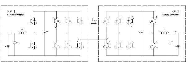
In this configuration, the two EVs are connected through their existing Type-2 charging ports. Power transfer is facilitated using the three-phase active rectifier switches. Specifically, during V2V charging, the top switch of one phase (phase-a, referred to as S1) and the bottom switch of another phase (phase-c, referred to as S6) of the providerEV’sactiverectifier-1areturnedON.Atthesame time, the corresponding switches (S’1 and S’6) of the receiver EV’s active rectifier-2 are also switched ON. This directlink between the intermediate DC-linksofbothEVs isillustratedinFigure2.
Throughout the V2V charging process, the four switches (S1, S6, S’1, and S’6) remain engaged, forming a dual bidirectional buck-boost converter. This arrangement enables controlled energy transfer between the two EVs, regardless of variations in their battery voltage levels. SincetheactiverectifiersofbothType-2chargersserveas an interface for linking the two DC-links, their usual rectificationfunctionisbypassed,andallotherswitchesof therectifiersremainOFFduringV2Vcharging.Depending on the battery voltage levels of the two EVs, the system
automaticallyoperatesindifferentenergytransfermodes, ensuringeffectiveandflexiblepowerexchange.
2.1.
WhenthebatteryvoltageofEV-1islowerthanthatofEV2,andtheirrolesasproviderandreceiveraredefined,two possible operating modes are identified. In the first case, when EV-1 acts as the provider, power flows forward, requiringa boostoperation toincreasethevoltage before transferring energy to EV-2. On the other hand, in the second case, when the power flow is reversed and EV-2 becomes the provider, a buck operation is necessary to step down the voltage before supplying power to EV-1. These operational modes ensure effective energy transfer between the two EVs, regardless of their battery voltage differences.
1) Forward Step-Up Mode (EV1 as Provider and EV2 as Receiver):
In this mode, EV-1 functions as the charge provider, and EV-2 acts as the charge receiver, with battery-1 having a lower voltage than battery-2. When the two EV batteries are directly connected using the proposed method by activating switches S1, S6, S’1, and S’6, the voltage of EV1’s battery is stepped up to match that of EV-2 by operating DC-DC converter-1 in boost mode. During the ON period of switch Sb1, inductor L1 stores energy from EV-1's battery, while switch Sa1 operates in complementarymodetoSb1.
When Sb1 turns OFF, Sa1 turns ON, allowing energy transfer from EV-1's battery and inductor L1 to EV-2's battery through S1, S’1, Sa2, and inductor L2. To enable power reception from the DC-links, switch Sa2 stays ON throughout the V2V charging process, ensuring that Vdc1 matchesVdc2,whichequalsVbat2.Meanwhile,switchSb2 switchesincomplementtoSa2,asillustratedinthefigure.
2) Reverse Step-Down Mode (EV1 as Receiver and EV2 as Provider):
Similartothe forward step-upmode, in this reverse stepdown mode, the EV batteries are linked by switching ON S1, S6, S’1, and S’6 of active rectifiers 1 and 2. DC-DC converter-1operatesinbuckmodetotransferpowerfrom EV-2’sbatterytoEV-1’sbattery.SinceVbat1islowerthan Vbat2, diode Da2 becomes forward biased, ensuring that Vbat2 equals Vdc1, which equals Vdc, allowing EV-2’s batterytoprovidepowertoEV-1throughtheDC-link.

International Research Journal of Engineering and Technology (IRJET) e-ISSN: 2395-0056
Volume: 12 Issue: 03 | Mar 2025 www.irjet.net p-ISSN: 2395-0072
During the ON period of switch Sa1, energy from EV-2’s battery is supplied to EV-1’s battery via inductor L1, Da2, S’1, and inductor L2, as shown in Figure 4(a). When Sa1 switchesOFF,thestoredenergyininductorL1isreleased throughswitchSb1,whichswitchesincomplementtoSa1, asdepictedinFigure4(b).
2.2. V2V Case-2: Vbat1 = Vbat2
Inthisscenario,wherebothEVbatteryvoltagesareequal, the DC-DC converters must be controlled such that one operates in a current-controlled boost mode while the otherfunctionsinacurrent-controlledbuckmode.
1) Forward Step-Up Mode (EV1 as Provider and EV2 as Receiver):
In this mode, where Vbat1 equals Vbat2, energy transfer from EV-1 to EV-2 is carried out by operating DC-DC converter-1inboostmodeandDC-DCconverter-2inbuck mode, both under closed-loop current control. During the ON period of switch Sb1, inductor L1 stores energy from EV-1’s battery, while switch Sa1 switches in complement toSb1.Simultaneously,switchSb2ofDC-DCconverter-2is turned ON to allow inductor L2 to freewheel energy, with switchSa2complementarily switched to Sb2, asshown in Figure5(a).
WhenSb1andSb2switchOFF,switchesSa1andSa2turn ON, facilitating energy flow from EV-1’s battery to EV-2’s battery through L1, S1, S’1, and L2, as shown in Figure 5(b). This mode can also be achieved by controlling the providerEV’sDC-DCconverterinvoltagecontrol modeto regulate the DC-link voltage at a level higher than the EV battery voltage, while the receiver-side DC-DC converter operatesincurrentcontrolmode.
2) Reverse Step-Up Mode (EV1 as Receiver and EV2 as Provider):
This mode is similar to the forward step-up mode, where Vbat1 equals Vbat2, but with the direction of power flow reversed. In this case, DC-DC converter-2 functions in boost mode, while DC-DC converter-1 operates in buck mode under closed-loop current control. Alternatively,
voltage control mode can also be applied to regulate the powertransferprocessinthismode.
2.3 V2V Case-3: Vbat1 > Vbat2
TheconverteroperationinthisscenarioissimilartoCase1,butwiththedirectionofpowerflowreversed.
1) Reverse Step-Up Mode (EV1 as Receiver and EV2 as Provider):
This mode resembles the forward boost mode, where Vbat1 is less than Vbat2, but with the power flow reversed.Inthiscase,DC-DCconverter-2ofEV-2functions inboostmode,whileswitchSa1oftheDC-DCconverter-1 inEV-1stayscontinuouslyON.
2) Forward Step-Down Mode (EV1 as Provider and EV2 as Receiver):
Thismodemirrorsthereversebuckmode,whereVbat1 is lessthanVbat2,butwithreversedpowerflow.Inthiscase, DC-DC converter-2 of EV-2 functions in buck mode, while switch Sa1 of the DC-DC converter-1 in EV-1 stays continuouslyON.
3. REGULATION STRATEGY FOR THE PROPOSED V2V METHOD
The charging rate and the quantity of energy transferred in the proposed V2V method are regulated by controlling the on-board converters. The mode selector flow, as illustrated in Figure 6, identifies the suitable V2V mode basedonthebatteryvoltagesofEV-1andEV-2,aswell as theirrespectiverolesasproviderandreceiver.Depending on the selected operating mode, the on-board charger convertersareadjustedaccordinglyto enableV2V energy transfer.
3.1 Operation of the Active Rectifiers as a V2V Interface
During standard three-phase AC charging using a Type-2 charger,theactiverectifierfunctionsind-qcontrol mode, converting three-phase AC to DC while ensuring unity power factor at the grid terminals. However, in the proposed V2V charging method, the active rectifier is reconfigured to serve as an interface for linking and enabling energy exchange between the two EV batteries. Once the Type-2 charger ports are connected for V2V charging, the gating pulses for switches S1 and S6 of the activerectifier-1inEV-1,alongwithswitchesS1andS’6of the active rectifier-2 in EV-2, remain continuously activated throughout the V2V charging process across all operatingmodes.
3.2 Regulation of DC–DC Converters
In the proposed V2V charging strategy using onboard chargers, the DC-DC converters of Type-2 chargers operate under a closed-loop current control system. For forward step-up and reverse step-down modes, where Vbat1islowerthanVbat2,theinductorcurrentIL1ofDC-

International
Volume: 12 Issue: 03 | Mar 2025 www.irjet.net p-ISSN: 2395-0072
DC converter-1 is regulated using a closed-loop mechanism. The error between the reference current IL* andtheactualinductorcurrentIL1isprocessedthrougha PI controller, which determines the duty cycle for switch Sa1,whileswitchSb1operatesincomplementarymodeto Sa1,asshowninFigure7.ThegatingsignalforswitchSa2 remainscontinuouslyactiveduringthismode.
The transfer function used to configure the PI controller forDC-DCconverter-1isdefinedbythedutycycle(D)and the load resistance (R2), which corresponds to the charging current of EV-2’s battery. The proposed V2V method enhancesefficiency, minimizes energylosses,and offers the advantage of connecting two EVs using the existing Type-2 charger ports, making it a flexible and practicalsolutionforEVusers.
For any V2V implementation, access to onboard instrumentation sensors and battery management system (BMS)controllersinboththeproviderandreceiverEVsis crucial for enabling communication between the two vehicles and retrieving the necessary parameters for energy transfer. The bidirectional power converter interface for V2V charging is assumed to be available, provided that commercial EVs have integrated communication systems and access to controllers and instrumentationsensors.
TheV2Vmodeselectiondependsonbatteryvoltagelevels, providerandreceiverpreferences,anduserinputs,which areobtainedthroughonboardinstrumentationsensors.As showninFigure6,theonboardDSPcontrollersdetermine the appropriate mode of operation (e.g., forward step-up) and regulate the power flow direction and the required amountofenergytransferaccordingly.
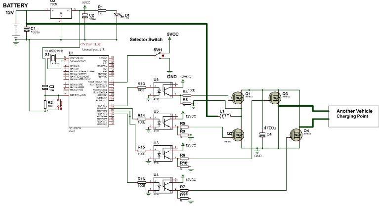
The IRF840 is an N-Channel Power MOSFET capable of switchingloadsupto500Vandhandlingcurrentsofupto 8A.Itrequiresagatethresholdvoltageof10Vbetweenthe GateandSourceterminalstoactivate.Duetoitshighgate voltagerequirement,itcannotbedirectlyconnectedtothe I/OpinofaCPU.IfaMOSFETwithalowergatevoltageis required, options such as the IRF540N or 2N7002 can be considered. The IRF540N, with a lower gate threshold voltage of around 4V, is more suitable for low-voltage microcontroller-based switching applications. The 2N7002 is a small signal MOSFET with a gate threshold voltage of approximately 2V, making it ideal for lowpowerswitchingandlogic-levelapplications.
MOSFETs play a crucial role in battery management systems (BMS) by acting as electronic switches for charging and discharging control. In electric vehicle applications, MOSFETs are used to regulate the flow of current between the battery and the load, ensuring efficientpowerdeliverywhileprotectingthebatteryfrom overcurrent conditions. A properly designed MOSFET switching circuit helps prevent overheating and improves the overall efficiency of the power system. Additionally, the use of high-performance MOSFETs enables precise control over power flow, which is essential for maintaining battery health and extending the lifespan of thebatterypack.
The PIC16F877 is a highly sophisticated microcontroller from Microchip, widely used for both modern and experimental applications due to its low cost, flexibility, high performance, and easy availability. It is ideal for use in machine control, measurement systems, and educational projects.ThePIC16F877features40pinsand includes multiple input/output (I/O) ports, analog-todigitalconverters(ADC),timers,andserialcommunication interfaces (SPI, I2C, and UART), making it suitable for complex automation and control systems. Its built-in EEPROM allows for data retention even after power loss, enhancingthereliabilityofapplications.

International Research Journal of Engineering and Technology (IRJET) e-ISSN: 2395-0056
Volume: 12 Issue: 03 | Mar 2025 www.irjet.net p-ISSN: 2395-0072
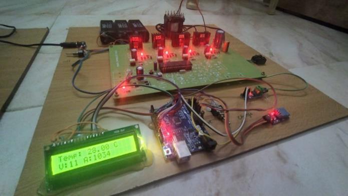
Inbatterymanagementsystems,thePIC16F877isusedto monitor and control various parameters such as battery voltage, current, and temperature. It can interface with temperaturesensorsliketheLM35andvoltagesensorsto continuously measure the state of the battery pack. The LM35 temperature sensor provides an analog output proportional to the temperature, which the PIC16F877 converts into a digital signal using its ADC module. This enables real-time monitoring and protection against overheating or thermal runaway, which is critical for maintainingbatterysafetyandperformance.
Similarly, voltage sensors measure the battery's terminal voltage and provide feedback to the microcontroller. The PIC16F877processesthisdataandadjuststhechargingor discharging cycle accordingly. This ensures that the battery operates within safe limits, preventing overcharging or deep discharge, which could degrade battery health. Additionally, the microcontroller can trigger protective actions such as disconnecting the load or activating a cooling system if the measured values exceed preset thresholds. This integrated control system enhances the safety, efficiency, and lifespan of the battery pack,makingthePIC16F877avitalcomponentinmodern batterymanagementsystems
5. SIMULATION DESIGN, SDG ADDRESSED & RESULTS
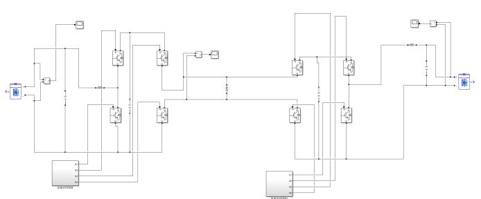
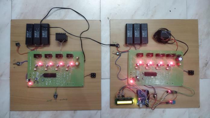
The simulation model illustrates a peer-to-peer (P2P) Electric Vehicle (EV) charging system, enabling one EV to directly supply power to another. This approach is particularly useful for addressing emergency charging scenarios, especially in remote or isolated areas where traditional charging infrastructure is unavailable. The model is implemented using MATLAB/Simulink (version 2020b) to simulate realistic charging and power transfer conditions between the vehicles. In the simulation setup, both the donor and receiver EVs are equipped with 48V, 100Ah lithium-ion batteries, ensuring a practical balance between energy storage capacity, portability, and overall system efficiency. The 48V configuration is chosen for its suitability in managing high-power transfers while maintaining safety and reliability. The model also incorporates real-time monitoring of battery voltage and current levels to optimize the charging process and
protect the battery from overcharging or deep discharge. Through this P2P charging method, the system enhances the feasibility of EV charging in off-grid or emergency situations, promoting greater flexibility and resilience in electricmobility.
Affordable and Clean Energy (SDG Goal 7): Electric Vehicle (EV) charging systems play a significant role in encouraging the widespread adoption of electric mobility, thereby reducing dependency on fossil fuels for transportation. By integrating clean energy sources such as solar and wind power into the charging infrastructure, EVs contribute to building a more sustainable and environmentally friendly energy ecosystem. The use of renewable energy for charging not only decreases greenhouse gas emissions but also promotes energy independence and long-term cost savings. Enhanced access to affordable EV charging stations powered by renewable sources supports the global shift toward cleaner transportation and aligns with the goal of increasing the proportion of renewable energy in the overall energy mix. This approach empowers consumers to transition to sustainable mobility solutions while fostering energy security and resilience in the transportationsector.
Climate Action (SDG Goal 13): Advanced EV charging infrastructure, particularly smart systems, is capable of seamlessly integrating with renewable energy sources such as solar panels and wind turbines.Thisfacilitatesefficientenergymanagementand helps reduce the overall carbon footprint of transportation. Technologies like vehicle-to-grid (V2G) and vehicle-to-vehicle (V2V) power sharing enable bidirectional energyflow,allowingEVstoserveasmobile energy storage units that can supply power back to the grid during peak demand periods or provide emergency supportinremotelocations.Thiscapabilityhelpsstabilize the energy grid, reduce reliance on conventional power generation, and support the transition toward a lowcarbon economy. By leveraging smart charging solutions and renewable energy integration, EV infrastructure becomesakeydriverofclimateaction,supportinga more sustainableandresilientglobalenergyframework.

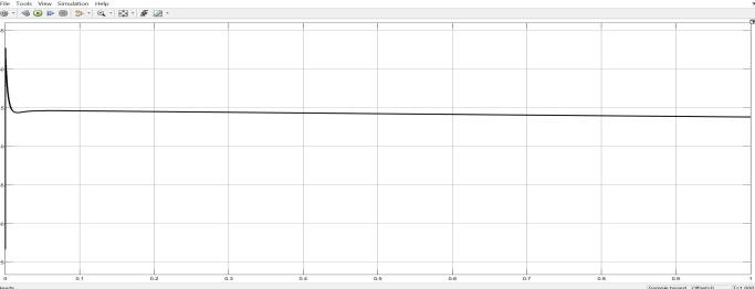
Theoutputvoltageconsistentlymaintainsastablelevelat 90V, with minor variations of less than ±1% ripple. The

International Research Journal of Engineering and Technology (IRJET) e-ISSN: 2395-0056
Volume: 12 Issue: 03 | Mar 2025 www.irjet.net p-ISSN: 2395-0072
system achieves rapid stabilization at 90V within just a few milliseconds, highlighting the effectiveness and precisionoftheconverter'scontrolmechanism.
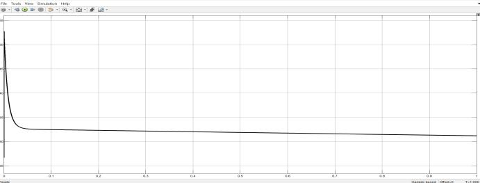
Similar to the 90V output, the 38V output remains steady withminimal ripple. Thislowervoltagelevel ensuressafe and efficient charging for auxiliary systems. Although it stabilizes slightly slower than the 90V output, the control settings are deliberately tuned to be less aggressive, prioritizingsafetyandreliability.
This paper introduces a direct vehicle-to-vehicle (V2V) chargingmethodthatenablespowertransferbetweentwo electric vehicles (EVs) without the need for external hardware or additional charging ports. This innovative approach provides a practical and effective emergency charging solution, especially in situations where AC grid access or DC fast-charging stations are unavailable. The proposed method allows for direct battery-to-battery connection through the onboard charger ports, significantly reducing the costs associated with additional hardware infrastructure. By bypassing redundant power conversion stages, the system improves overall efficiency and minimizes energy losses, enhancing the charging process'sreliabilityandperformance.
ThedirectV2Vchargingmechanismleveragestheexisting power architecture of the EV, ensuring compatibility without requiring any modifications to the vehicle's electricaldesign.Thissolutionisparticularlybeneficialfor addressing range anxiety among EV users, as it facilitates energy sharing between vehicles in remote or off-grid locations. The proposed system also enables cooperative energy exchangeamongEVs,promotinggreaterflexibility
and resilience within the electric mobility ecosystem. The control algorithm used in the V2V charging system ensures stable power transfer, maintaining consistent voltage and current levels throughout the charging process.
Furthermore, the effectiveness and practicality of the proposedV2Vapproachare thoroughlyvalidatedthrough extensive MATLAB/Simulink simulations and a scaled experimental prototype. The simulation results demonstrate that the system achieves rapid stabilization withminimalvoltageripple,highlightingtheaccuracyand responsiveness of the control strategy. Experimental data further confirms the system’s ability to maintain high efficiency under varying load and environmental conditions. By eliminating the need for complex and expensive charging infrastructure, this direct V2V charging method provides a scalable and cost-effective solutionforenhancingtheaccessibilityandconvenienceof EVcharging.
[1] S. D. Vasconcelos et al., "Assessment of Electric Vehicles Charging Grid Impact via Predictive Indicator,"inIEEEAccess
[2] Y. Tian et al., "Control Multiplexing and Switching Methods for Bi-Directional EV Chargers," 2024 InternationalConferenceonEnergyandElectrical Engineering (EEE), Nanchang, China, 2024, pp. 17.
[3] J. Yang, G. C. Lim, C. Hwang and J. -I. Ha, "TwoPhase DC Charging Method for Improved Efficiency and Zero Torque in Motor-Integrated Charger," in IEEE Transactions on Industrial Electronics
[4] H. Yang et al., "Optimization Scheduling Method for Electric Vehicle Charging and Swapping Stations Based on Elastic Load Regulation Potential," 2024 IEEE 2nd International Conference on Image Processing and Computer Applications (ICIPCA), Shenyang, China, 2024, pp. 1962-1966.
[5] K. Arulvendhan, S. K. Nagaratnam, R. Narayanamoorthi, A. H. Milyani, S. Alghamdi and M.Alruwaili,"PrimarySideHybridReconfigurable Compensation for Wireless EV Charging with Constant Current/Constant Voltage Control," in IEEEAccess,vol.12,pp.149960-149976,2024
[6] P.Vinay,S.K.Suresh,V.D.Ganesh,T.V.Krishna,A. S.GaneshandC.Saiprakash,"DesignandAnalysis of Rotor Technology for Electric Vehicle Application," 2023 International Conference on Power, Instrumentation, Energy and Control (PIECON),Aligarh,India,2023,pp.1-4
[7] S.RandR.Manjunatha,"DesignandTestingofan Integrated Electric Vehicle Model," 2021 IEEE

International Research Journal of Engineering and Technology (IRJET) e-ISSN: 2395-0056
Volume: 12 Issue: 03 | Mar 2025 www.irjet.net p-ISSN: 2395-0072
Mysore Sub Section International Conference (MysuruCon),Hassan,India,2021,pp.703-710.
[8] S. B. Kazeem Pasha and V. Champa, "Design and Development of Regenerative Suspension System for EV Applications," 2023 IEEE International ConferenceonPowerElectronics,SmartGrid,and Renewable Energy (PESGRE), Trivandrum, India, 2023,pp.1-5
[9] M. H. S. M. Haram, M. T. Sarker, G. Ramasamy and E. E. Ngu, "Second Life EV Batteries: Technical Evaluation, Design Framework, and Case Analysis," in IEEE Access, vol. 11, pp. 138799138812,2023.
[10] V. P. Keseev, "Electric Bicycle Design Experiences and Riding Costs," 2020 7th InternationalConferenceonEnergyEfficiencyand AgriculturalEngineering(EE&AE),Ruse,Bulgaria, 2020,pp.1-4
2025, IRJET | Impact Factor value: 8.315 |