
International Research Journal of Engineering and Technology (IRJET) e-ISSN: 2395-0056
Volume: 12 Issue: 03 | Mar 2025 www.irjet.net p-ISSN: 2395-0072


International Research Journal of Engineering and Technology (IRJET) e-ISSN: 2395-0056
Volume: 12 Issue: 03 | Mar 2025 www.irjet.net p-ISSN: 2395-0072
Athif Ahammed Kutty 1 , Yadunandhan S G 2 , Kasinath P K 3 , Abishek K 4 Jibi R5
1234Graduate Student, 5Assistant Professor Department of Mechanical Engineering, AWH Engineering College Calicut, Kerala, India ***
Abstract – Industry is always move fast to produce variety of products. Sheet metal have wide application in manufacturing industry like automobile, aerospace industry and medical industry. In industry sheet metal operations are carried out by manually or with the use of fluid power. Hydraulic fluid power systems are not suitable for small and medium scale industry. Compressed airistheoneoftheeasiest sources of energy. Pneumatic fluid power system has wide range of feasibility in point of view of industrial applications. Objective of the project work is to Simulate and develop a pneumatic system consist multiple actuators used to perform sheet metal operations clamping, bending and forming.
Key Words: Pneumatics, Simulation, Hydraulic fluid power,Sheet metal.
1.INTRODUCTION
Today highly competitive industry needs developing new technologies.Automationplayskeyroleinindustrytosave material,labourandimprovingdeliveringqualityproduct. Sheet metal operations are one of the fundamental operations in metal working. Sheet metal operations are usuallycarriedoutbymanuallyorfluidpower.Insmalland medium industry hydra ulic machines are not feasible. Pneumaticpowersystemgainedimportanceinthefieldof automation. Pneumatics is the branch of technology that deals with use of compressed air to produce motion. In pneumatics air is using as the working fluid. The word pneumaticsderivedfromtheGreekpneumameaningbreath or air. Pneumatics is the application of compressed or pressurized air to power machine to control or regulate them.Pneumaticsalsodefinedasbranchoffluidpowerthat deals with generation, transmission and control of power using pressurized air. An air compressor converts mechanical energy of primover in to pressure energy of compressedair.Pneumaticsystemconsistcompressor,FRL unit, direction control valve and actuators. Actuators are either reciprocating actuators or rotating actuators. Actuatorsconvertpneumaticenergyintomechanicalenergy. Simulation always play a vital role in manufacturing industry. Effective pneumatic system requires effective workingsimulation.FluidSIMisasoftwaretoolforcreating simulatinghydraulic,pneumatic,electro-hydraulic,electropneumaticdigitalelectronicsystem.
Main aim of project work is design simulate and developmentofpneumaticsequentialcircuitA+B+B-C+C-Aconfiguration. Which is widely used for sheet metal operationlikeclamping,bendingandformingetc.
1.DevelopingMultiple-ActuatorPneumaticCircuitsUsing theKarnaughMapsDesigningPLCControlled
Author:AlZahraaN.Fawzi,MaherY.Salloom
Aimofthisworkistodevelopmultiple-actuatorpneumatic circuits and reduce start-up times by merging various operationalsequencesintoasingleprocess.TheKarnaugh maps is a technique for reducing logical equations or transforming truth tables into logic circuits. The method allowsforcircuitcontrolusingaprogrammablecontroller (PLC). ThestudyfocusesuseKarnaughMapstodevelopa pneumatic control system in difficult cases with three different control sequences for five cylinders. Simulation softwareforpneumatic/electro-pneumaticcircuitsisutilized toapplythetechnique(AutomationStudioandFluidSim).
2.DesignandDevelopmentofPneumaticSheetMetalCutting Machine
Author:Sudarshan.U,SunilKumarK,DarshanS.R,Kushal. P,Varshith.N
Thispaperpresentsanefficientandcost-effectivemethod forshearingsheetmetalusingapneumaticactuationsystem that can be applied in small and medium-scale industries. This work provides a safe and effective way to cut sheet metalwithminimalmaintenancecosts.Thecuttingthickness range can be increased by arranging a high-pressure compressorandinstallingmorehardenedblades.
3 DevelopmentofPneumaticSheetMetalShearingProcess forPreciseCutting
Author:DurairajR,MuruguNachippan,Tamilarasan
Thisworkproposesapneumatic-basedcuttingmachinethat cuts small sheets and pipes instantly. Manual cutting machines waste time and aren't accurate enough for

International Research Journal of Engineering and Technology (IRJET) e-ISSN: 2395-0056
Volume: 12 Issue: 03 | Mar 2025 www.irjet.net p-ISSN: 2395-0072
production.Thepneumaticcuttingmachinealwayscutsat thesamepace,ensuringconsistentoutput.Themachinehas apneumaticcylinderwithaconnectinglink.Assemblingthis joint requires a cutter blade. With a bed, material can be supportedhorizontallyinfrontofthecutter.
Author: MuhammedIshackV,AhammedAdilP,AmalPK, RohithVT,JibiR
This project work consists design simulation and developmentofcascadepneumaticsequentialcircuit.Main aim of work is design simulate and development of pneumatic cascade sequential circuit A+B+B-Aconfiguration. Pneumatic diagram describes the relation betweeneachpneumaticcomponentsasperequipmentof pneumaticsystem.Mostofthepracticalpneumaticsystems involvetheuseofmultipleactuators(cylinders,semi-rotary actuators,etc.)whichwhenoperatinginspecifiedsequences carry out the desired control tasks. In multicylinder applications A+B+B-A- has wide applications. Sheet metal operation in a press shop, a stamping operation is to be performedusingastampingmachine.Theworkpiecehasto be first clamped under the stamping station. Then the stampingtoolgetsintopositionandperformsthestamping operation.Theworkpiecemustbeunclampedonlyafterthe operation is completed. The cascade system provides a straightforwardmethodofdesigningsequentialcircuits.It willalwaysgiveaworkablecircuit.
Author:Prof.SunilParge,MalgudriSaraswati,RasikaPasare
Inthisworkfabricatethepneumaticcircuitwithtimedelay circuit forging machine. It time delay valve has three different times like, low, medium, high. It controls by a button and it consist many more electric and electronic components. This circuit run on adapter this adapter provides 12-volt DC current. This pneumatic circuit also havecomponentslike,compressor,FRLunit.Pressuregauge, 3/2solenoidoperateddirectioncontrolvalve,doubleacting cylinder,etc.
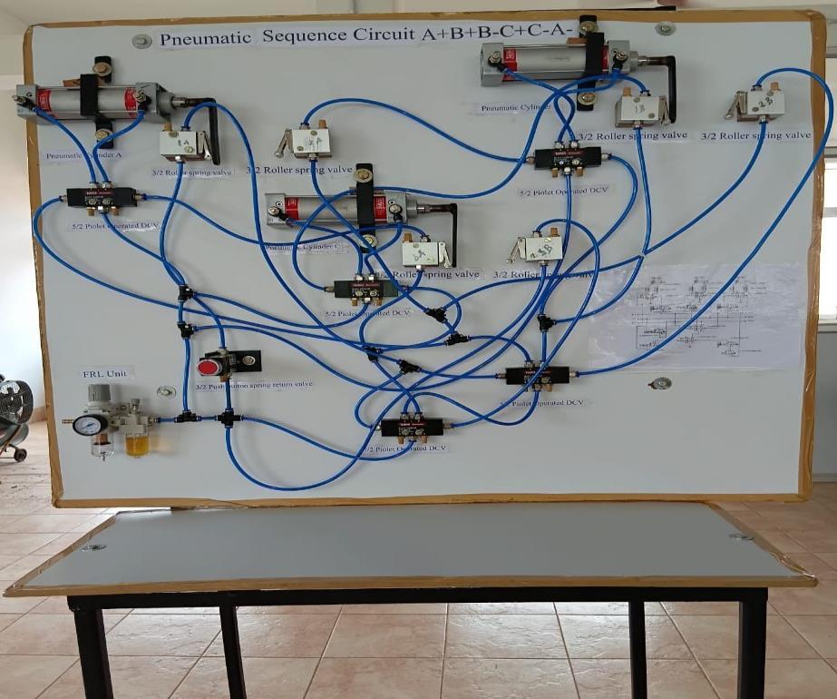
Methodology is one of the most critical elements to be considered to make sure the fluent of the project and get expected result. In other words, the methodology can be describedasframeworkwhereitcontains theelementsof theworkbasedontheobjectivesandascopeoftheproject. Agoodframeworkcangettheoverallviewoftheprojectand getthedataeasily.Thisincludedliteraturestudy,Designof pneumaticcascadecircuitA+B+B-C+C-A-,simulationusing
Fluid SIM software, fabrication of pneumatic sequential systemandcostanalysis.
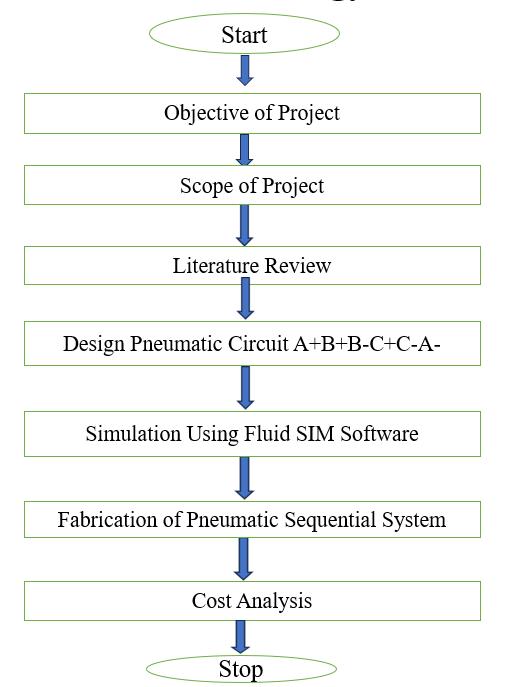
1:ProjectMethodology
Metalstripisbendusingabendingmachine,wheretheyare placedmanuallyinafixture.CylinderAclampthemetalstrip whenapushbuttonispressed.CylinderBstartthebending operation and retract, and cylinder C completes the operation. After cylinder C returns to its initial position cylinderAreleasesthepart. Operationhastoperform
BendingOperation
FormingOperation

Fig1:SheetMetalComponent

International Research Journal of Engineering and Technology (IRJET) e-ISSN: 2395-0056
Volume: 12 Issue: 03 | Mar 2025 www.irjet.net p-ISSN: 2395-0072
PositionalDiagram
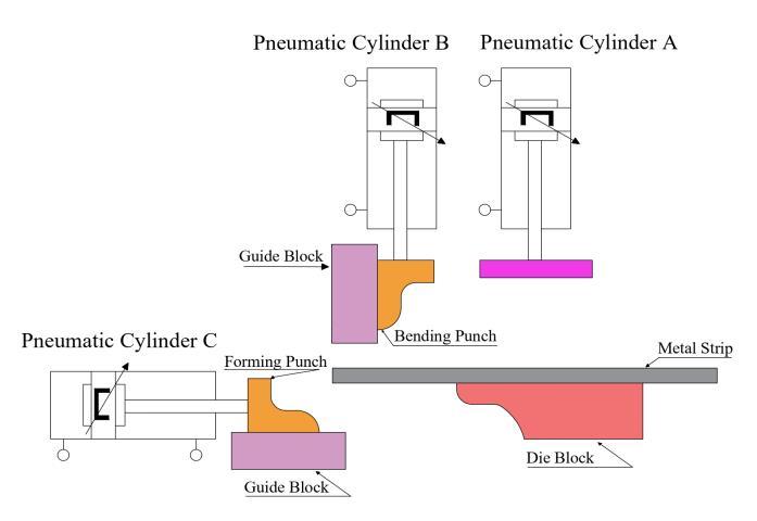
Fig2:PositionalDiagram
Stage1:Clamping
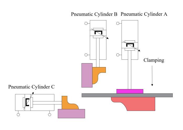
3:Stage1ClampingProcess
Stage2:Bending
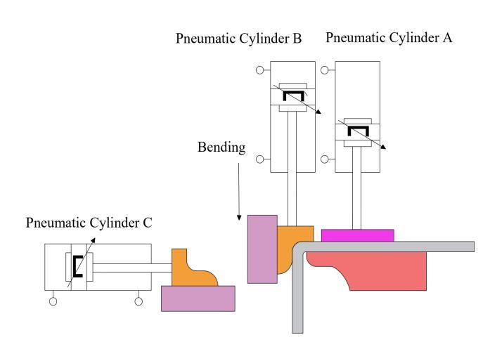
Stage3:Forming
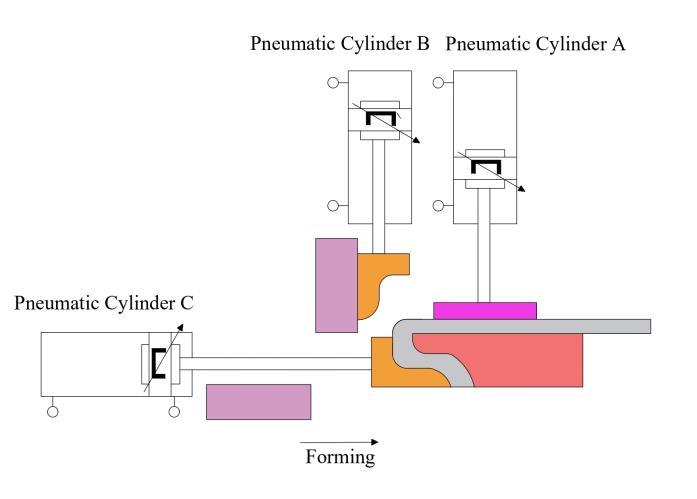
Fig5:Stage3FormingProcess
FlowChartforPneumaticCircuitDesign
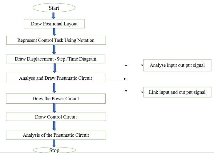
Fig6:FlowChartforPneumaticCircuitDesign
Step1:Positionallayout

Fig7:PositionalLayout

International Research Journal of Engineering and Technology (IRJET) e-ISSN: 2395-0056
Volume: 12 Issue: 03 | Mar 2025 www.irjet.net p-ISSN: 2395-0072
Step2:RepresentControlTaskUsingNotation
CylinderAadvancingisdesignatedasA+
CylinderAretractingisdesignatedasA-
CylinderBadvancingisdesignatedasB+
CylinderBretractingisdesignatedasB-
CylinderCadvancingisdesignatedasC+
CylinderCretractingisdesignatedasC-
ThesequencingofpneumaticcylinderisA+B+B-C+C-A-
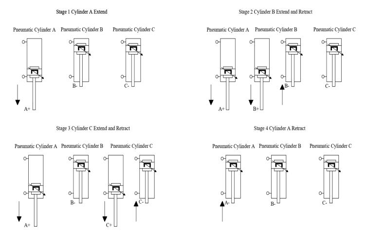
Fig8:PositionalLayoutwithNotation
Step3:Displacement–StepDiagram
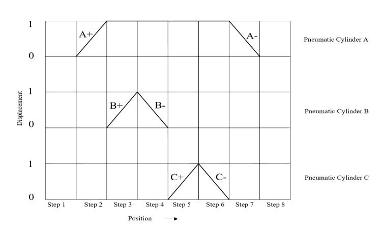
Fig9:Displacement-StepDiagram
Step4:Displacement–TimeDiagram
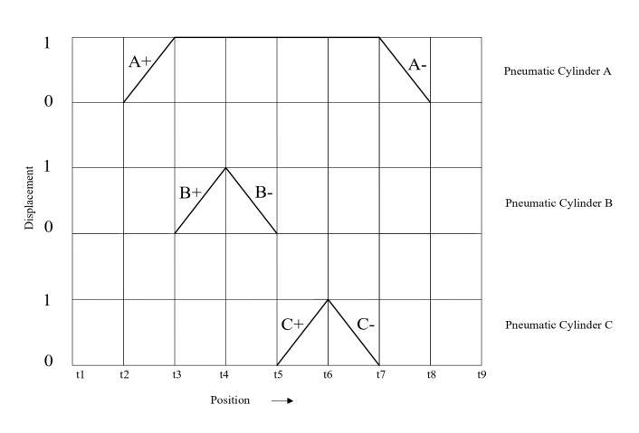
Fig10:Displacement-TimeDiagram
Step5:AnalyseandDrawthePneumaticCircuit
Step5.1AnalyseinputandOutputSignal
InputSignals
CylinderA:Limitswitchathomepositiona0
Limitswitchathomepositiona1
CylinderB:Limitswitchathomepositionb0
Limitswitchathomepositionb1
CylinderC:Limitswitchathomepositionc0
Limitswitchathomepositionc1
OutputSignal
ForwardmotionofcylinderA(A+)
ReturnmotionofcylinderA(A-)
ForwardmotionofcylinderB(B+)
ReturnmotionofcylinderB(B-)
ForwardmotionofcylinderB(C+)
ReturnmotionofcylinderB(C-)

International Research Journal of Engineering and Technology (IRJET) e-ISSN: 2395-0056
Volume: 12 Issue: 03 | Mar 2025 www.irjet.net p-ISSN: 2395-0072
Step5.2DisplacementStepdiagramlinkedtoinputoutput signal
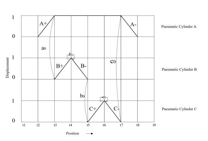
Fig11:DisplacementStepdiagramlinkedtoinputoutput signal
A+generatesensorsignala1,whichisusedformovementB+
B+ generate sensor signal b1, which is used for group changing
B-generatesensorsignalb0,whichisusedformovementC+
C+ generate sensor signal c1, which is used for group changing
C-generatesensorsignalc0,whichisusedformovementA-
Step6:PneumaticCascadeCircuitA+B+B-C+C-A-
Noofgroups=3
Group1:A+B+
Group2:B-C+
Group3:C-A-
Noofpressureline=Noofgroup =3
Selectionofvalve
Noofpioletoperated5/2valve=Noofcylinders=3
Nooflimitvalve=Noofcylinderx2=3x2=6
Noofgroupchangingvalve=Noofgroup-1=3-1=2
ComponentsofPneumaticSequentialSystem
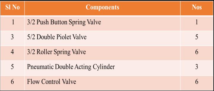
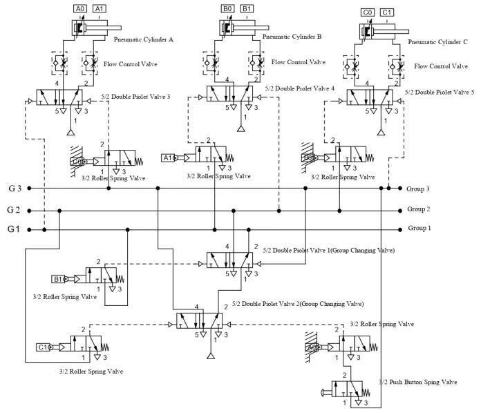
12:PneumaticCircuitA+B+B-C+C-AFirstCycleA+B+Group1Selected
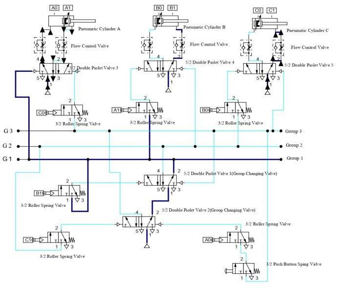
Fig13:PneumaticCircuitA+B+

International Research Journal of Engineering and Technology (IRJET) e-ISSN: 2395-0056
SecondCycleB-C+Group2Selected
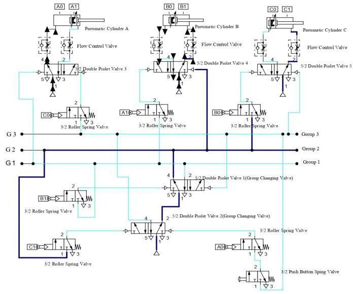
ThirdCycleC-A-Group3Selected

GroupChangingValve
Volume: 12 Issue: 03 | Mar 2025 www.irjet.net p-ISSN: 2395-0072 © 2025, IRJET | Impact Factor value: 8.315 | ISO 9001:2008
Forgroupingchangingcascadevalve5/2doublepioletvalve using
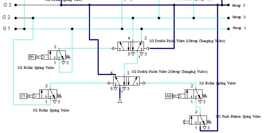
Control Signal given this side Group 1Selected
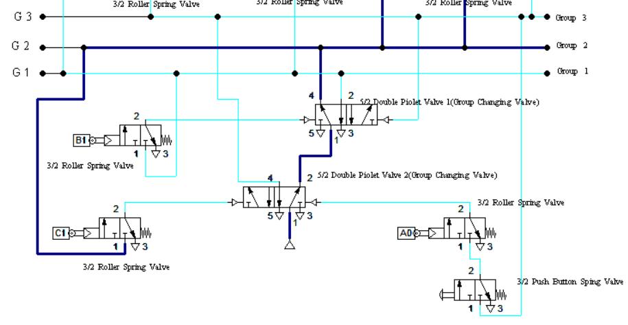
Control Signal given this side Group 2 Selected
Control Signal given this side Group 3 Selected
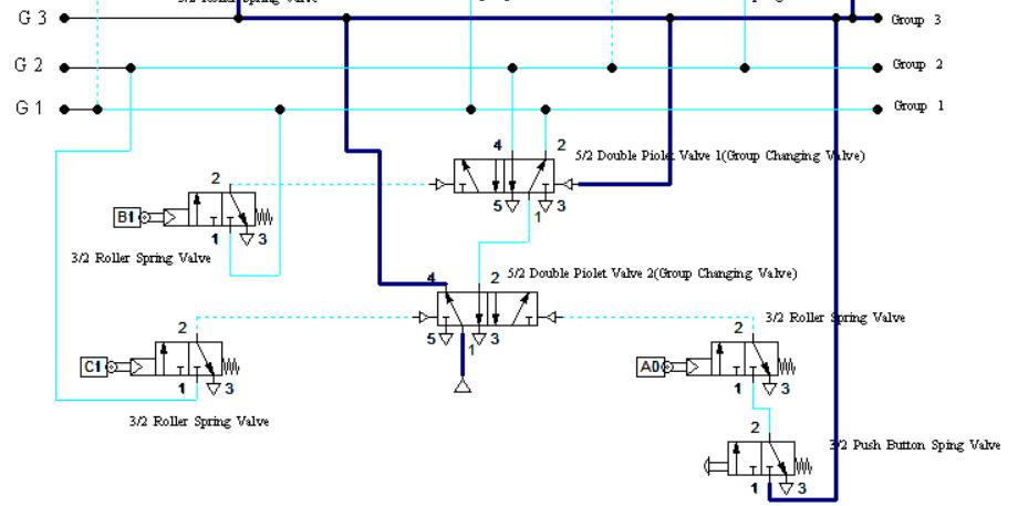
Control Signal given this side Group 3
Selected
Fig16:GroupChangingValve
PowerCircuit–PneumaticCylinder
5/2 Double Piolet valve used for actuating double acting cylinder. Flow control valve used to control flow of compressedairintocylinder.

Volume: 12 Issue: 03 | Mar 2025 www.irjet.net
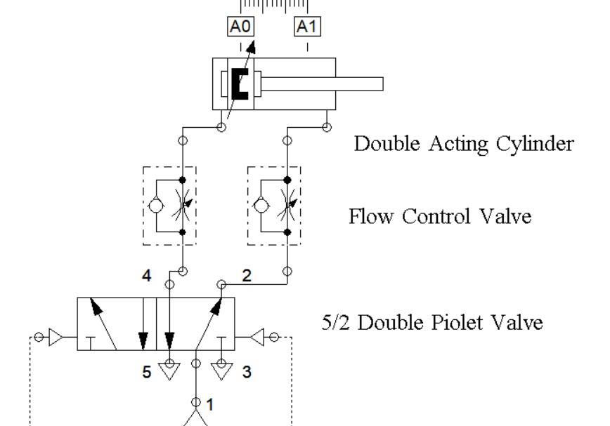
Fig17:Powercircuit5/2DoublePioletoperatedDCV
5. FUTURE WORK
Futureworkisdevelopinganelectro-pneumaticcircuitfor pneumatic sequential circuit A+B+B-C+C-A-Simulation of electrical ladder diagram easily converted in to a PLC programmingladderdiagramforabovesequentialmotion andsimulatedusingFluidSim-Pneumaticsoftware.
In multicylinder applications A+B+B-C+C-A- has wide applications. Sheet metal operation in a press shop, Metal strip is bend using a bending machine operation like clampingbendingandformingwilltakeplacesequentially.
[1] AlZahraa N. Fawzi, Maher Y. Salloom “Developing Multiple-Actuator Pneumatic Circuits Using the Karnaugh Maps Designing” Journal Européen des Systèmes Automatisés Vol. 56, No. 2, April, 2023, pp. 245-252
[2] Sudarshan. U, Sunil Kumar K, Darshan S. R, Kushal. P, Varshith. N “Design and Development of Pneumatic SheetMetalCuttingMachine”.InternationalJournalof Scientific Research in Mechanical and Materials Engineeringhttps://doi.org/10.32628/IJSRMME.

International Research Journal of Engineering and Technology (IRJET) e-ISSN: 2395-0056
Volume: 12 Issue: 03 | Mar 2025 www.irjet.net p-ISSN: 2395-0072
[3] Durairaj R, Murugu Nachippan, Tamilarasan “Development of Pneumatic Sheet Metal Shearing Process for Precise Cutting” International Journal of ResearchPublicationandReviewsISSN2582-7421
[4] MuhammedIshackV,AhammedAdilP,AmalPK,Rohith V T4 Jibi R “Design Simulation and Development of Sequential Pneumatic Circuit For Industrial Applications” International Research Journal of EngineeringandTechnology(IRJET)
[4] Shubham Gump Alwar, Darshan Dhabarde, Shubham Gade,AmitKalhane,VishnuNair,Prof.PrafulRandive. “DesignandFabricationofPneumaticCarLifter”IJARIIE Vol-4Issue-22018
[5] Mauton Gbededo and Olayinka Awopetu “Design and ConstructionofAutomatedStampingMachineforSmall Scale Industries” International Journal of Engineering Research & Technology (IJERT) Vol. 6 Issue 12, December–2017
[6] R.Sasikala,M.Rakshana,T.Thinaa,P.Thirupponvel,D. Vasanth “Automatic Bar Bending Machine using PneumaticSystem”InternationalJournalofInnovative TechnologyandExploringEngineering (IJITEE)ISSN: 2278-3075(Online),Volume-9Issue-5,March2020
[7] Bhavik Ranjan Kathe “Pneumatic Can Crusher” International Research Journal of Engineering and Technology(IRJET)Volume7Issue5May2020.
[8] M.PapoutsidakisA.ChatzopoulosD.Tseles“Hydraulics andPneumatics:ABriefSummaryoftheirOperational Characteristics”JournalofMultidisciplinaryEngineering ScienceandTechnology(JMEST)Vol.5Issue10,October –2018
[9] Mr.MayurD.ThoratProf.PatilA.R.“DesignandAnalysis of Pneumatic Pick & Place Mechanism” IJSRDInternational Journal for Scientific Research & Development| Vol. 7, Issue 05, 2019 | ISSN (online): 2321-0613.
[10] Thokale Manoj, Kothwal Satish, Kotkar Rahul, More Suyog, Pawase Mahesh. “Design and fabrication of pneumaticbarbendingmachine”InternationalResearch Journal of Engineering and Technology (IRJET) Volume:04Issue:03|Mar-2017
[11] Jagadeesh T “Pneumatics: Concepts, Design and Applications”UniversitiesPress(India)PrivateLimited ISBN:9788173719417.


Mr. Athif Ahammed Kutty FinalYear B-tech student in the Mechanical Engineering Department at AWH Engineering College Calicut Kerala India.
Mr. Yadunandhan S G Final Year Btech student in the Mechanical Engineering Department at AWH Engineering College Calicut Kerala India.
Mr. Kasinath P K Final Year B-tech studentintheMechanicalEngineering Department at AWH Engineering CollegeCalicutKeralaIndia.
Mr. Abishek K Final Year B-tech student in the Mechanical Engineering Department at AWH Engineering CollegeCalicutKeralaIndia.
Mr.Jibi.R Currently working as an Assistant Professor in the mechanical engineering department at AWH EngineeringCollegeCalicutKeralaIndia. He has published 17 International journals and presented two articles in international conference. He has more than 12 years experience in teaching and one-year Industrial experience in Press tool and Mold making. His interested area is computer aided design and analysis, Production Technology, Industrial hydraulics and Pneumatics