
International Research Journal of Engineering and Technology (IRJET) e-ISSN: 2395-0056
Volume: 12 Issue: 04 | Apr 2025 www.irjet.net p-ISSN: 2395-0072
International Research Journal of Engineering and Technology (IRJET) e-ISSN: 2395-0056
Volume: 12 Issue: 04 | Apr 2025 www.irjet.net p-ISSN: 2395-0072
Soham Bhoje,1 , Rushikesh Kaveeshwar2 , Gayatri Kulkarni3 , Anand Shinde4, Archit Jayachandran5 , S.M.Dhaneshwar6
6Assistant Professor , Dept. of Mechanical Engineering ,JSPM’S Rajarshi Shahu College of Engineering Pune, India 12345UG student, Dept. of Mechanical Engineering ,JSPM’S Rajarshi Shahu College of Engineering Pune, India
Abstract - The car washing industry consumes a significant amount of water which is usually wasted after the washing is completed. The wastewater contains wastes like oil, grease, soap, dust, and odour which make it unusable for any further applications. The research aims to design a fully automatic car washing and filtration system using sensors, chemicals, and electronic controls. The system consists of three primary stages namely, soap removal, oil removal and chlorination. By integrating automation and smart filtration, this solution reduces freshwater consumption, lowers water disposal, allows reuse of water for multiple but limited cycles, and enhances sustainability in the car washing industry. The paper discusses design of the system, costs involved and the manufacturing plan. It also discusses the future scope of the project and focuses on its implementation into an existing car washing center.
Key Words: Filtration, Wastewater, Sustainability, Automated
We came up with our current problem statement after the severe water crisis incident that shook Bangaloreinearly2024.Asthewatercrisistightened, ithitmanybusinessesreliantonwaterespeciallythe car washing business. The Bangalore water supply and sewage board banned the use of corporation water for non-essential purposes like car washing, laundryetc.sendingripplesthroughtheindustry.Theban, accompanied by a hefty fine of ₹5,000 for every violation, hasleftmanycarwashingcentersgrapplingwithfinancial losses and operational constraints. With borewell water and tanker water being the primary source for these businesses, the ongoing water scarcity has amplified their woes.
Every day, car washes use an enormous amount of water, and most of it goes straight down the drain. The dirty water,filledwithsoap,oil,grease,andgrime,notonlygets wasted but also pollutes the environment. On top of that, traditionalfiltrationmethodsrequirealotofmanualeffort, makingthewholeprocessinefficientandexpensive.
Toaddressthesechallenges,weproposeafullyautomated water treatment system that minimizes human intervention while optimizing filtration and reuse. This system will incorporate sensors and electronic controls to monitor and purify water efficiently, allowing multiple reuse cycles instead of unnecessary wastage. By reducing operational costs and promoting sustainability, this solution will offer an eco-friendly and cost-effective approach for car wash businesses, ensuring integration intoexistingsetups.
The system will include soap removal, oil separation, and chlorination to effectively remove contaminants, allowing treated water to be reused for multiple wash cycles.Thesolutionwillbedesignedtofitintoexistingcar wash infrastructure with minimal changes, making it a practical choice for businesses. The project will focus on designing a fully automated car washing and wastewater filtration system using sensors, pumps, and electronic controls to minimize manual intervention. By recycling water,thesystemwillhelpreducefreshwaterconsumption and prevent contaminated wastewater from being discharged into the environment. The system will be designed for fresh and lightly contaminated car wash wastewater and may not be suitable for highly toxic or hazardouswastetreatment
1. Understanding the Problem & Requirements : Astudy was conducted by visiting car washing centers in the PCMC area. These included medium sized and small sized centers. It was concluded that around 100-150 liters of water is used washing a normal mid- sized passenger vehicle. The major contaminants include soap,oil,grease,dust,andodour.Therequirementisto cleanthesewastes.
2. SystemDesign&ComponentSelection:Aprocessflow wasdecidedforwasteremovalandaroughlayoutwas created for the system. This included finalizing the processes for waste removal and components for the same.Chemicalstobeused,pumpsanditscalculation,
International Research Journal of Engineering and Technology (IRJET) e-ISSN: 2395-0056
Volume: 12 Issue: 04 | Apr 2025 www.irjet.net
system for washing the vehicle, valves required was decided.
3. Automation & Sensor Integration: To automate the wholesystemvarioussensors,valves,microcontrollers wereselectedandaconnectioncircuitwasestablished for working of the whole system. Similarly, the automatic car washing system was created in electronicperspective.
4. CAD model creation: CAD models for different filtration units was created in detail with all the components installed and was connected through piping. The automated washing system was also createdconsidering.
5. Feasibility, Cost and Manufacturing: The design was analyzedonbasisofexistingcentersanditsfeasibility was checked. Cost validation and analysis was conducted to estimate the approximate price of the system. A bill of material was created for the componentsused.Similarly,amanufacturingplanwas createdforthesystem.
MAOMAO ZHANG in their paper ‘Design of Automatic Car Washing Machine System based on Image Processing’ mentionedthatthecarwashingmachinecontrolsystemis consistofimageacquisitionandprocessingmodule,sensor module, system control module and motor drive module. The image acquisition and processing module adopts an industrial-grade camera to capture images on the upper and two sides of the vehicle and then transmits the acquired images to the control unit. The control unit first runs the corresponding image processing algorithm to obtain the position information of the dirt points (such as sludge, bird excrement and other dirt that are not able to be removed easily) on the surface of the vehicle to be cleaned.Then,thecoordinatesaresenttothecarwashing control unit, the car wash control unit obtains the coordinates of the body dirt point and sends the coordinates information to the car washing controller to conductaremaincleaningoperationonthedirtpoints.The sensor module contains a peripheral ultrasonic ranging sensor and a pressure sensor. The purpose of the allarounddistancemeasuringsensoristodeterminewhether the parking position is suitable after the vehicle is driven into the washing machine. If it is not suitable, the normal operation cannot be worked and the vehicle is prompted to move the position. The pressure sensor is installed on the spray bar of the car washer. Once the pressure is abnormal, it will stop working immediately. The car washing motor module consists of a water pump motor, a three-phase stepping motor, an air compressor, and a single-phase asynchronous motor. The three-phase stepping motor, a limit switch and a single-phase asynchronous motor control operation of the automatic car washing machine spray bar. The water pump motor and the air
p-ISSN: 2395-0072
compressor separately provide high-pressure water and air outlet for the spray bar to complete the high-pressure car washing and air-drying process.
MOHAMMED CHATOUI, AMANE JADA, SALAH SOUABI in their paper ‘Removal of Wastewater Soaps by Coagulation Flocculation Process’ mentioned that in the present work, attempts are made to examine the effectiveness of the coagulation process, by using ferric chloride (FeCl3 6H2O), as coagulant, for the treatment of theindustrialwastewatersoaps.Thus,variousparameters characterizing the removal of wastewater soaps, such as the organic matter amount, expressed as chemical oxygen demand (COD), the aqueous phase pH, the aqueous solution turbidity, and the residual surfactant amount, were investigated in the presence of coagulant. Furthermore, the optimum conditions, leading to efficient coagulation, were achieved by varying both, the coagulant dosage, and the pH of the aqueous solution, and by using jar-testexperiments.Thedatarevealedthatintherangeof pH = 2-13, the optimal pH value, giving the best removal performance, was found to be equal to 8.5. Further, the highest values, expressed in percent, for the COD, the turbidity removal, and the surfactant removal, from the wastewater soaps, were found to be, respectively, 98%, 99%,and 75%, and they were achieved by theadditionof 800 mg L-1 FeCl3 6H2O to the wastewater soaps. It is clearlydemonstratedthatthecoagulationmethodisuseful forthepre-treatmentprocessoftheindustrialwastewater soapsandprerequisitepriortobiologicaltreatment.
The experimental coagulation process in general consistedofthreesuccessivestagesa-b-c:
a. An initial rapid mixing, between the coagulant and the wastewatersample,during5minatagitationspeedof160 rpmtookplace,followedby,
b. Aslowmixingstageduring20minat30rpm,
c.Afinalsettlingstepofthemixturewhichtook60min.
WENJUN QU, ZHILE WANG, XIANGYU WANG, ZHE WANG, DEHAI YU, DANDAN JI in their paper ‘Highhydrophobic ZIF-67@PLA honeycomb aerogel for efficient oil–water separation’ mentioned that adsorption is considered the best technique for oil–water separation because it can be applied on a large scale, is environmentally friendly, and produces no harmful byproducts. Among these methods, oil phase adsorption materialsthatcanbeselectivelyadsorbedandhavespecial high hydrophobicity have attracted mentioned that widespread attention from the academic community. For example, metal meshes, sponges/aerogels, polyethylene bundles and membrane materials have been extensively studiedasoil-phaseadsorptionmaterials.
International Research Journal of Engineering and Technology (IRJET) e-ISSN: 2395-0056
Volume: 12 Issue: 04 | Apr 2025 www.irjet.net
L. L. ROSE, L. H. ENSLOW in their paper ‘Odor Control by Chlorination’ mentioned that Chlorine removes odors from water primarilyby oxidizing the compounds responsible for those odors, such as hydrogen sulfide and certain organic matter.While not the primary focus for odor removal, chlorine is also a disinfectant, killing bacteria,viruses,andothermicroorganismsthatcancause disease.
ANKEM SUSHEEL, S. SELVENDRAN in their paper ‘Investigation on Water Level Regulation Using Floating Sensor and Arduino Uno’ mentioned that Floating ball is suspended over the overhead tank. It is connected to the floating switch, which consists of normally open and normally closed switches. The positive part of DC input from Arduino UNO is connected to normally opened terminal of the floating switch. When water level in the overhead tank is not full, then bob goes down and the switch remains closed thereby it does not pass voltage at the output of floating switch and remains as open circuit. When water level rises, the bob rises and the floating switch connected to bob which is normally open, closes, therebypositivepartofDCvoltageisreceivedattheoutput of the floating switch. This positive part of DC voltage is given as input to the voltage divider circuit which acts as voltmeter. At the voltage dividing point of the circuit, the output is taken and is connected to analog input pin of Arduino UNO. Therefore, if voltage appears across the analog input terminal of Arduino UNO, it is assumed that overheadtankisfullandif0voltsappearsasinputacross the analog input terminal of Arduino UNO, then it is assumedthatoverheadtankisnotfull.
SANTOSHANGADI,ROBERTJACKSON intheirpaper‘A critical review on the solenoid valve reliability, performance and remaining useful life including its industrial applications’ mentioned that Solenoid valves (SVs) are electrically controlled electromechanical devices used togovern the flow ofliquids orgases. Solenoid valve converts electrical energy into mechanical motion or mechanicalenergy.Asolenoidvalveprimarilyconsistsofa solenoid (insulated coil made up of copper) and a valve body.Theotherkeypartsofitareplunger(armatureorthe core),seal,spring,orifice,shadingring,inletportandoutlet port.
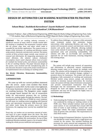
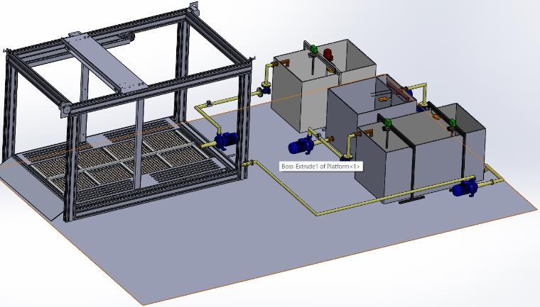
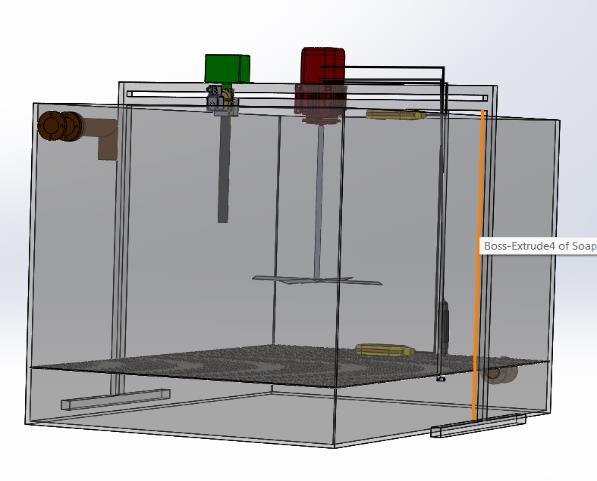
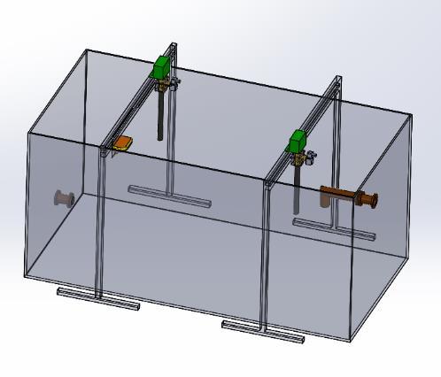
The washing system features a stainless-steel gantry that moves along precision-aligned guide rails, ensuring complete vehicle coverage. A spray bar with adjustable nozzles controls water and detergent flow, adapting to different car types. the system integrates a multi-stage purification process that filters, restores, and recycleswastewater.UsedwaterfirstentersTank1,where achemicaltreatmentandmixingturbineremovesoapand foam. It then flows to Tank 2, where a honeycomb structureextractsoilandgrease.Finally,thewaterreaches
p-ISSN: 2395-0072
Tank 3, where chlorination disinfects it before being recycled for reuse. The system features automated water flow monitoring, ensuring smooth operation by balancing tank levels and preventing overflow. Smart sensors, emergencystopmechanisms,andpressurecontrolsystems ensuresafetyandefficiency.
The automated car washing system intelligently analyses image data to determine key factors such as vehicle size and shape, dirt intensity, detergent requirements, and nozzle movement speed. By leveraging advanced image processing, the system ensures that each wash is customized for the specific needs of the vehicle, optimizingcleaningefficiency.
To regulate water and detergent usage, the system employsmotorizedpumpsandactuatorsthatdynamically adjust the flow rate, detergent concentration, and spray pressure based on the vehicle's level of dirt and size. A real-time monitoring system continuously tracks water and detergent consumption, ensuring that only the necessary amounts are used. This minimizes waste, reduces operational costs, and promotes eco-friendly practices. The gantry movement and spray coordination are fully automated, allowing the system to move smoothly along precision-aligned guide rails. The spray barsadjustinreal-time,ensuringuniformcoverageacross the vehicle, including hard-to-reach areas. If the system detects excess dirt buildup, it automatically increases the spray intensity and pressure for those specific sections, guaranteeing a thorough cleaning. For safety and operational efficiency, the system includes a limit switch thatautomaticallyshutsoffpoweroncethewashingcycle is complete. Additional safety mechanisms include emergency stop buttons to halt operations instantly, overpressure release valves to protect water pumps, and automated error detection that notifies operators of any malfunctions. The spraying system consists of highpressure nozzles mounted on a gantry spray bar, which regulate water flow and detergent distribution based on the vehicle type and dirt level. These nozzles dynamically
Volume: 12 Issue: 04 | Apr 2025 www.irjet.net
adjust their angles and intensity, ensuring an efficient cleaning process while preventing excessive use of resources.Specializednozzlestargetspecificareassuchas wheels, undercarriage, and roof, delivering a deep and precisecleanforanenhancedwashingexperience.
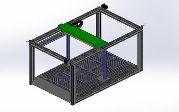
As the vehicle is washed, dirty water carrying debris,soap,oil,andothercontaminantsflowsdownward into the filtration system. The first stage of filtration involvesacoarsemeshfilter(10mmsize),whichcaptures larger debris suchasplasticwrappers,leaves,andstones, preventing them from entering the purification process. The mesh is designed with enough clearance from the vehicle floor to allow debris to accumulate without causingclogs,ensuringasmoothwaterflow.Oncepastthe coarse mesh, the water moves to the fine mesh filtration stage (5mm size), which further refines the cleaning process by capturing smaller particles like dirt clumps, microplastics, and fine solid waste. The spacing between the coarse and fine mesh layers prevents rapid clogging, maintaining efficient filtration. The filtered water then flows into a central accumulation tank, where water from all eight mesh systems converges. The tank is designed with a gradual slope, ensuring that water naturally flows towardoneend,whereapumpisstrategicallyplaced.This prevents water stagnation and improves the efficiency of the filtration and transfer process, allowing the purified watertomoveseamlesslyintothenextstageoftreatment.
The water purification process begins as wastewater from the vehicle wash flows through a mesh filtration system, which removes large debris and solid particles. This pre-filtered water is then pumped into the soapremovaltank,whereitaccumulatesuntil itreachesa preset level, ensuring the right amount of water is availablefortreatmentbeforetheprocessbegins. Awater level sensor installed inside the tank continuously monitors the water level. When the water reaches 20% capacity,thesystemensuresthatthereisenoughwaterto start the treatment, while the 95% level prevents overflow. Once the required level is reached, the sensor sends a signal to the electronic control system, triggering the next stage of filtration. The Arduino-based control system then activates the chemical dosing process, releasingapreciseamount ofFerricChlorideandCalcium Hydroxide through a solenoid valve. This controlled chemical release ensures effective soap neutralization without excessive chemical waste. At the same time, a mixing motor (0.37 kW A.C.) powers a turbine, which vigorouslystirsthewater,ensuringthatthechemicalsmix evenlywiththesoapmolecules.Asaresultofthisprocess, solidsoapresidues(flocs)formduetoachemicalreaction between the soap and the treatment chemicals. These residues become denser than water and settle at the bottomofthetank,preventingthemfrominterferingwith further filtration. To optimize energy use, the Arduino system uses a timer to control the mixing duration, ensuring the turbine runs only as long as needed before automatically shutting off. Once the mixing stops, solid soap residues remain trapped at the bottom by a fine stainless-steel mesh, allowing only clean, soap-free water torisetothetop. The water outletpipe,positionedabove the mesh, ensures that only purified water is pumped to thenextstageoffiltration,whilethesoapresiduesremain contained. This automated process guarantees efficient soap removal, making the water suitable for further purification and reuse, reducing waste, and promoting sustainablewatermanagement. International Research Journal of Engineering and
International Research Journal of Engineering and Technology (IRJET) e-ISSN: 2395-0056
Volume: 12 Issue: 04 | Apr 2025 www.irjet.net
Methods used to treat50mLwater
Reviewofthetreatment
SandFiltration Limited effectiveness in removing dissolvedsoaps.
Treatment with ActivatedCarbon
TreatmentwithAlum
Treatment with FerricChloride
Treatment with CalciumHydroxide
Treatment with Ferric Chloride & CalciumHydroxide
Periodic replacement of Activated Carbon & limited effectiveness for inorganiccontaminants.
Generates sludge that requires disposal and residual aluminum in treatedwatermayposehealthrisks.
Causes staining and the sludge coagulated has to be filtered further, and the pH of the product is in acidic range.
Causesalotofsludge&thepHofthe productwas14
Thetreatmentresultsinclearsolution, and optimum pH of 7-9 can be obtained with specific quantity of Ca(OH)2concerningFeCl3
3.4 Oil Filtration System
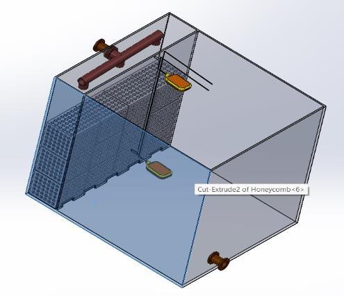
The oil separation process begins when soaptreatedwaterfromthepreviousfiltrationstageispumped intotheoilseparationtank.Thistankisequippedwith12 vertically stacked honeycomb structures made from oleophilic (oil-attracting) and hydrophobic (waterrepelling)materialslikepolypropylene.Thesehoneycomb structures increase surface area, enhancing the efficiency of oil separation by attracting oil droplets while repelling water, ensuring effective filtration. As the oilcontaminated water flows through the tank, the honeycomb surfaces trap oil droplets, while the heavier water moves downward due to gravity. Over time, the trappedoildropletsmergeintolargerclusters,preventing them from mixing back into the water. This natural coalescence process ensures that oil is efficiently separated before the water continues to the next stage.
p-ISSN: 2395-0072
Thecleaner,denserwatersettlesatthebottomofthetank andisdirectedintoasidestoragetankthroughdesignated bottom openings, ensuring a continuous flow of oil-free water for further purification or reuse. Meanwhile, the trapped oil continues to accumulate on the honeycomb surfaces over multiple cycles. To maintain efficiency, the honeycomb structures require periodic cleaning. This is donebywashingthemwithacontrolledflowofwaterora mild detergent solution, which loosens the accumulated oil, allowing it to be collected separately for disposal or recycling. This automated and sustainable separation process ensures that water is effectively purified while minimizing oil waste, promoting environmentally responsiblewatermanagement.
After passing through the previous filtration stages, including oil removal, the treated water flows into a 1500L storage tank, where it begins to accumulate. As the water level gradually rises, a level sensor installed at 95%capacitycontinuouslymonitorsthevolumeinsidethe tank.Thissensorplaysacrucialroleinensuringthewater istreatedefficientlybeforemovingtothenextstage.Once the water level reaches 95%, the sensor triggers the electronic control system (Arduino), which initiates the chlorinedosingprocesstoeliminateanylingeringodours. The dosing system operates through two solenoid valves, ensuring a precise and controlled release of chlorine. The primary solenoid valve opens first, allowing a measured flowofchlorinefromthechemical storagetank,whilethe secondary solenoid valve fine-tunes the dosing process to prevent excessive chemical use. This automated system ensuresthatthecorrectamountofchlorineisintroduced, effectively neutralizing odours while maintaining water quality. By integrating real-time monitoring and controlledchemicaldosing,theprocesspromotesefficient and sustainable water treatment, preparing the purified waterforreuseorfurtherrefinement.
International Research Journal of Engineering and Technology (IRJET) e-ISSN: 2395-0056
Volume: 12 Issue: 04 | Apr 2025 www.irjet.net
3.6
The selection of the centrifugal pump for this system is basedonkeyperformancefactors,ensuringefficientwater transfer while optimizing energy consumption. The flow rate, measured in litres per minute (LPM), is carefully chosen to match the required water transfer speed, ensuring smooth operation without unnecessary delays. Theheadpressure,ortheheight thepumpmust pushthe water,dependsontheverticaldistancebetweentanksand friction losses in the pipes. Since the tanks are positioned atnearlythesameheight,alow-headpump(5-10meters) is sufficient, as the primary resistance comes from pipe friction rather than elevation. For material selection, durable and corrosion-resistant materials such as cast iron,stainlesssteel,orthermoplasticsarepreferred,asthe water being pumped is non-corrosive. A horizontal centrifugal pump is chosen as it provides high efficiency for moderate flow and pressure requirements, making it the most suitable and widely used option for this type of system. The motor power selection is based on the requiredflowandhead.A0.5 HPpumpisidealforsmallscale water transfer, handling up to 50 LPM, which aligns with the system’s needs. The pump operates on a singlephase (230V) supply, as it is suitable for small-scale applications
Forconnectivityandpipecompatibility,thepumpfeatures flanged or threaded fittings, ensuring a secure and leakproof connection with the 50mm inlet and outlet pipe diameter.
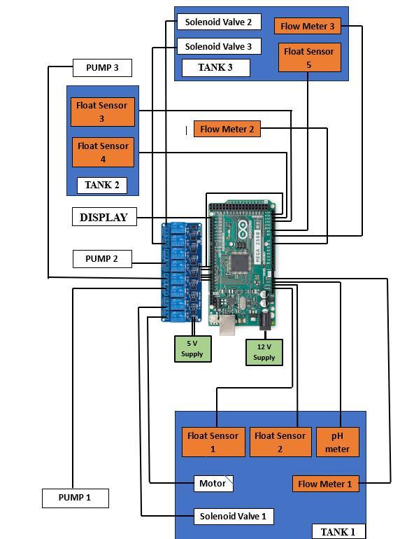
The automated water filtration and restoration system is designedusinganArduinoMega2560Rev3asitscentral control unit. This microcontroller features 54 digital I/O pins and 16 analog inputs, enabling it to read sensor data andcontrolvarioussystemcomponents.Itreceivesinputs fromfloatsensors,apHmeter,andflowmeters,whilealso managing the operation of pumps, solenoid valves, and a mixing motor through an 8-channel relay module. The relay module acts as an electrical switch, allowing the
p-ISSN: 2395-0072
ArduinotoefficientlyturnpumpsandvalvesONorOFFas required. A display module is connected via I2C or SPI to provide real-time system parameters, including water levels, flow rates, pH values, and the status of pumps and valves.Toautomatewaterlevel monitoring,multiplefloat sensorsareinstalledacrossthesystem’stanks.Tank1has two sensors to detect the minimum and maximum water levels,ensuring waterisprocessedin batches.Tank 2 has sensors to prevent overflows and monitor when it is empty or full, while Tank 3 includes an additional float sensor to trigger overflow protection. The process begins with Pump 1, which transfers water from the washing system into Tank 1, where soap removal occurs. Float sensors detect water levels, ensuring treatment begins only when enough water has accumulated. Once the level is sufficient, the mixing motor activates, and chemical dosing is initiated to neutralize soap residues. After soap removal, Pump 2 transfers water from Tank 1 to Tank 2, where oil separation takes place using honeycomb structures. Flow meters track water movement, ensuring efficient filtration. In Tank 2, oil droplets adhere to the honeycomb structures, allowing cleaner water to settle at the bottom. Once the required level is reached, Pump 3 transfers this oil-free water into Tank 3, where chlorination and final storage occur. The solenoid valves precisely control the release of chlorine to eliminate any remaining contaminants. The system is powered by a 5V supply for the 8-channel relay module and a 12V supply fortheArduino,ensuringreliableoperation.
International Research Journal of Engineering and Technology (IRJET) e-ISSN: 2395-0056
Volume: 12 Issue: 04 | Apr 2025 www.irjet.net p-ISSN: 2395-0072
Thesystembeginswiththecollectionofwastewatersfrom the car washing area, which first flows into a mesh filtration tank. This tank serves as the primary filtration point, removing larger debris and contaminants. Once filtered, the water is collected in a mesh system tank equippedwithapumpthatoperatesbasedonthereal-time conditions of the downstream tanks. This pump activates only if the soap filtration tank is not full and is not undergoingpurification.Ifthesoaptankisalreadyfullbut not actively purifying water, the system intelligently redirects the flow straight to the oil filtration tank. The soap filtration stage plays a key role in treating water containing detergents and cleaning agents. This tank is equipped with two level sensors placed at 20% and 95% capacity, and it only accepts water if it is below 95% and not currently running its purification cycle. During the purification process, which lasts for approximately 30 minutes,apHsensormonitorsthewaterquality.Basedon the readings, an Arduino-controlled solenoid valve administerstheappropriateamountofFerrousChlorideto neutralize the soap content. Simultaneously, a motordriven turbine begins to stir the contents using a timerbased control circuit. During this treatment phase, all waterflowishaltedtomaintainisolation.Post-purification, the tank releases water only if the oil filtration tank has capacityandisnotfull.Flowmetersandnon-returnvalves ensure accurate flow tracking and prevent backflow. Next, the water enters the oil filtration tank, which is also equipped with level sensors at 20% and 95% capacity. Entry into this tank is conditional upon the completion of soap treatment and available space in the oil tank. A honeycomb structure inside the tank helps separate and trapoilefficiently.Oncethewaterlevelinthistankreaches a predefined threshold, a second pump is activated to transfer the water to the final storage tank, provided the storage tank is not already at 95% capacity. This movement is also monitored using a flow meter and protected by a non-return valve. The last stage of the processisthestorageandodorremovaltank.Waterflows into this tank only if it is not full and the oil tank has completed its transfer. A chlorine dosing system is integrated here to eliminate bacteria and odor, ensuring the water is safe and clean for reuse. A single float sensor prevents overflow by halting incoming flow and, if necessary, opening a solenoid valve to discharge excess water. When clean water is required for reuse in the car washing system, a third pump directs it through a distribution manifold with three separate outlets, supplying water to overhead gantry nozzles, side jets, and underbodysprayers.
To have a perfectly matched feature one must have to prepare it first. This belongs to a concept called interest points/features.Hereblobsareaveryusefulindicatorsfor
feature matching as their intensity of occurring at a particular region is constant as blobs has fixed positions and definite size such that they can be used to rectify matchingofthefeaturesinthegivenimage.
For blobs like features to be useful we need its attributes determining,
Locationoftheblob
Sizeoftheblob
Orientationoftheblob
Formulate a description that is independent of sizeandorientationoftheimageitself.
It is crucial to understand edge detection and its algorithms,inthiscaseweareusinggaussianfilter G(x, y) = (1 / (2 * π * ^2)) * exp(-(x^2 + y^2) / (2 * ^2)) for 2D, which is used to reduce edge noise, by convoluting it with the function of the image X. We can find the edge of theimagebyapplyingfirstderivativeofgaussian G(x, y) =
√ [ ] and convolve with image function to obtain the peak of edge of the image. Also applying gaussian second derivative one would find the edges distinct zero-crossing becoming more smoother edges. Theresponseoftheoperatordependsonthesigmavalue, As the sigma gets wider its own peak value begins to fall, that is then the response of the operator also decreases. Thischangesthescaleandtheresolutionoftheimage. By using normalizing technique, we would vary the scale of theimage,herebyvarying( )scalewillchange.Whilewe increase the sigma value the blobs start to attain its peak showing their maximum intensity or response. Here we are getting two pieces of information i.e., the position of the blob and the size of it. More the scale value to reach the peak of the blob more will be its size. Characteristic scale is proportional to the size of the blob. For twodimension blob detection Normalized Laplacian of Gaussian is used as an equivalent. Location of blobs is found by its local extrema after applying normalized Laplacian of gaussian at many scales. For selection of the sigma values to generate a scale space, it can be formulatedas,
Wherek=0,1,2,3….n istheinitialscale
S istheconstantmultiplier
Concept of SIFT Descriptors:
Descriptors signify the matching points of features given in two or more different images. It produces a gradient direction whichishavingorientationinfluenceusing KNN and other algorithms. We can find a match between features of different images even though they are having different scales, resolutions, orientations and captured fromdifferentviewpoints.Wecomputethemagnitudeand
International Research Journal of Engineering and Technology (IRJET) e-ISSN: 2395-0056
Volume: 12 Issue: 04 | Apr 2025 www.irjet.net p-ISSN: 2395-0072
orientation of the gradient features inside a standard (4x4x8)gridandplotthehistogramtofindtheinfluenceof the orientation within the grid. For calculating the difference between two features that tells the matching intensities between each other we’re comparing two arraysofdata,letH1(k)andH2(K)betwoarraysofdataof lengthN.
Smaller the distance matric, better the match of the features. d(H1, H2) = 0 For saying when it’s a perfect match. This could also be performed by Normalized Correlationtechnique.
d(H1, H2) = Σκ[(Η₁ (k) – Η₁)(H2(k) - H₂)] /√ – –
where: Hi = ∑
Some types of invariances while detecting the feature matchare:
Scaleinvariance
Rotationinvariance
Robustnessinvariance
Tostitchimagestogetherapplyingdetectingandmatching techniques will promote an enhanced panorama. The geometricrelationshipamongstthemshouldbedefined.It meansthatwhatisthetransformationthatassistsforover lappingoneimageontoanother.Thatprocessofwrapping one image to the coordinate frame of the other is called homography. Homography is the transformation matric thattakesanimagefromoneplanetoanotherbutthrough aspecificpointofprojection.
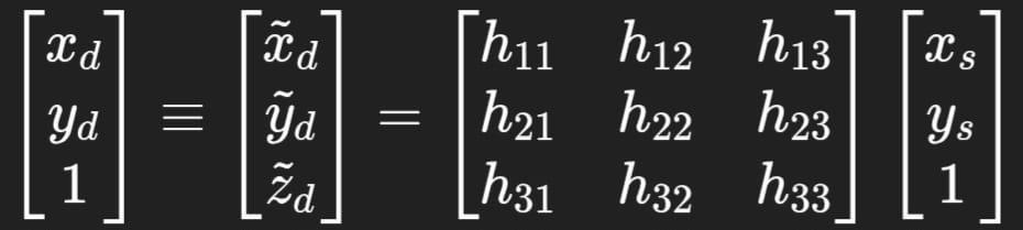
We can find the eigenvector H with smallest eigenvalue ofmatrixATAthatminimizeslossfunctionL(H).

There is one issue due to the curvature of the lens of camera which induces a problem of seamed stitched imagesafterapplyingthegeometrictransformation.Noto images are actually captured with exactly the same exposure and the radiometric response of the lens varies slightly over the view of the lens, this effect is called as vignetting effect. To perform homography first it’s
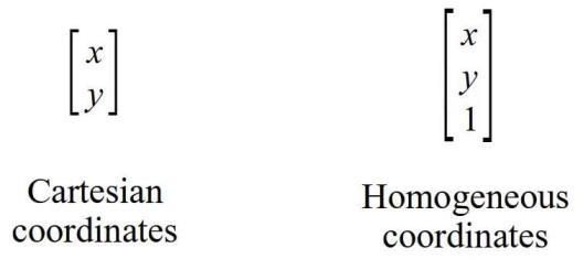
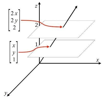
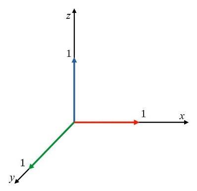
necessary to understand some transformations which are the equations and matrices that are used to manipulate the pixel values of an image. In the case of 3D image processing where viewpoints could also differ, then it at maximumtimescorrespondstoprojectivetransformation. When one takes a photo with the camera, 3D scene is projected to 2D camera sensor, this mapping is called perspectiveprojection.Anobjectorpartofanobjectin3D worldappearssmallerasdistancetocamera increases, as a result ratio of dimensions of an object changes. We can say that perspective projection preserves lines but may notpreserveanglesandtheratiooflengthsovereachline. Wewillberequiringhomogeneouscoordinatestoaddone more dimension to the cartesian coordinate. In a homogeneous coordinate system, a point and its scaled versionslet’ssayby(t)termsaresame.Theimageisthen warpedwhichisobtainedbyshearingin3Dspaceparallel toz-axisandthenmappingresultsbackonto2Dcartesian coordinate. Projective transformation is controlled with 8 parameters;therefore,ithas8DOF
International Research Journal of Engineering and Technology (IRJET) e-ISSN: 2395-0056
Volume: 12 Issue: 04 | Apr 2025 www.irjet.net p-ISSN: 2395-0072
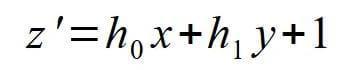
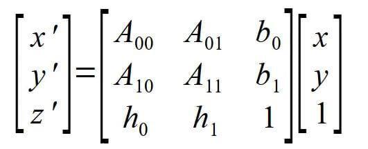
From affine matrix we insert two entries which is a h vectorconsistingof [h0, h1]
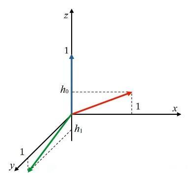
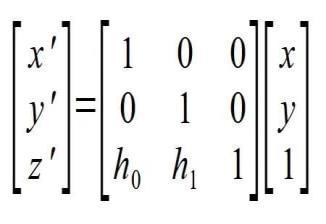
Here h0, h1 0 forprojective matrix. These vectorsshown in the image basis vectors and what h0 and h1 does is it change the orientation of those basis vectors as shown in theimage.Thenh0 andh1 shearthe3Dspaceparalleltoz axis which is denoted by z’. Combining this effect with A transformation matrix and b translation vector, different perspectivescanbeobtained.
4. Conclusion
Thisprojectsuccessfullydemonstratesthedesign of an automated water filtration, restoration, and reuse system tailored for car wash facilities. By integrating multiple filtration stages, including soap removal, oil separation, and chlorination, the system ensures that wastewater is effectively treated and made reusable, significantlyreducingwaterwastage.
Theuseofautomatedsensors,pumps,andsolenoidvalves controlled by an Arduino Mega 2560 allows for efficient, real-time monitoring and operation with minimal human intervention. The incorporation of float sensors, pH
monitoring, and flow meters enhances process accuracy, ensuring optimal water quality at every stage. Additionally, the honeycomb-based oil separation system improves efficiency while keeping maintenance requirementslow.
By implementing this system, car wash businesses can reduce their dependency on freshwater sources, lower wastewater disposal costs, and contribute to sustainable water management. Future improvements could focus on AI-drivenwaterqualityanalysis,solar-poweredoperation, or enhanced filtration technologies to further enhance efficiencyandsustainability.
[1] Maomao Zhang, “Design of Automatic Car Washing Machine System based on Image Processing” Academic Journal of Engineering and Technology Science, ISSN 2616-5767 Vol. 2, Issue 4: 30-35, DOI: 10.25236/AJETS.2019.020405 M. Young, The Technical Writer’s Handbook. Mill Valley, CA: UniversityScience,1989.
[2] Mohammed Chatoui, Amane Jada, Salah Souabi, “Removal of Wastewater Soaps by Coagulation Flocculation Process”, Journal of Colloid Science and Biotechnology,Vol.5,212-217,2016.
[3] L.L.Rose,L.H.Enslow,”OdorControlbyChlorination” ,SewageWorksJournal,July1931
[4] Wenjun Qu, Zhile Wang, Xiangyu Wang, Zhe Wang, Dehai Yu, Dandan Ji, ‘High-hydrophobic ZIF-67@PLA honeycombaerogelforefficientoil–waterseparation’
[5] Yu Meng and Bernard Tiddeman, “Implementing the Scale Invariant Feature Transform (SIFT) Method”, Department of Computer Science University of St. Andrews
[6] Szeliski, R. 2004. “Image alignment and stitching: A tutorial.” Technical Report MSR-TR-2004-92, MicrosoftResearch
[7] Mikolajczyk and Schmid, 2005“A performance evaluation of local descriptors”, In European Conference on Computer Vision (ECCV), Copenhagen, Denmark
[8] Tali Dekel MIT, Advances in computer vision Image Features,Homography,RANSACandPanoramas
[9] Rajput,R.K.FluidMechanics,andHydraulicMachines. S.ChandPublishing